Home / Heating
Back
Published: 05/13/2020
Reading time: 6 min
0
6691
Modern heat supply schemes have an extensive heating network, with several heating circuits. Despite the good thermal efficiency of such systems, serious hydraulic problems arise. Due to high resistances in the network, heating water is not always correctly distributed along the circuits, which causes an imbalance in the system.
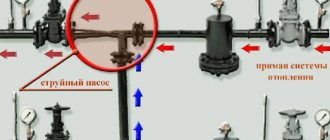
The correct piping of the boiler with a hydraulic arrow can level the situation. This coolant distributor operates reliably in three piping schemes and can be installed in any position
- 1 What is a hydraulic arrow
- 2 Purpose of the hydraulic arrow 2.1 In which case you can’t do without it
- 2.2 Operating modes
- 5.1 How to choose a hydraulic gun
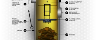
How does a hydraulic arrow work?
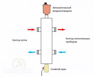
The hydraulic arrow is a flask with an automatic air vent installed in the upper part. Nozzles are cut into the side surface of the housing to connect the main heating pipes. Inside, the hydraulic arrow is absolutely hollow; a threaded pipe can be cut into the lower part for installing a ball valve, the purpose of which is to drain settled sludge from the bottom of the separator.
Essentially, a hydraulic needle is a shunt that short-circuits the supply and return flows. The purpose of such a shunt is to equalize the temperature of the coolant, as well as its flow in the generating and distribution parts of the hydraulic heating system. To obtain a real effect from a hydraulic separator, a careful calculation of its internal volume and the insertion points of the pipes is required. However, most of the devices on the market are mass-produced without adaptation to a specific heating system.
You can often come across the opinion that additional elements must be present in the cavity of the flask, such as flow dividers or meshes for filtering mechanical impurities or separating dissolved oxygen. In reality, such modernization methods do not demonstrate any significant effectiveness and even vice versa: for example, if the mesh is clogged, the hydraulic arrow completely stops working, and with it the entire heating system.
Schemes for self-manufacturing hydraulic arrows
When assembling a hydraulic arrow with your own hands, the main thing is to make the calculations correctly and have the skills to work with a welding machine.
First of all, it is necessary to find the optimal dimensions of the hydraulic separator:
- internal diameter: divide the sum of all heating boiler capacities in kW by the temperature difference between the supply and return, take the square root of the resulting parameter, and then multiply the last value by 49;
- height: multiply the inner diameter by six.
- spacing between pipes: multiply the internal diameter by two.
Based on the obtained parameters, you need to draw up a drawing or use one of the diagrams of the future hydraulic distributor presented by the Plumber Portal resource. After this, you need to prepare a steel tube of round or square cross-section, which corresponds to the calculated indicators, and weld the required number of pipes with threaded connections into it.
Despite the simplicity of the device, the characteristics of the hydraulic gun must still correspond to specific conditions. Also, when assembling it yourself, you need to understand what to start from.
The classic assembly of a typical hydraulic boom is based on the “three diameter rule”. That is, the diameter of the pipes is three times smaller than the diameter of the main cylinder of the separator. The pipes are diametrically opposite, and their height arrangement is also tied to the main diameter.
Some change in the position of the pipes is also used - a kind of “ladder”. This modification is aimed mainly at more efficient removal of gas and insoluble suspended matter. When circulating through the supply pipe, a slight change in the direction of the liquid flow in a zigzag downward manner contributes to the best elimination of gas bubbles.
Exceeding this limit is prohibited. The lower the speed of the vertical flow, the more effective the separation of air and sludge will be. The slower the movement, the better the mixing of flows with different temperatures. As a result, a temperature gradient is formed along the height of the device.
If the heating system contains circuits with different temperature conditions, then it is worth using a hydraulic distributor that acts as a collector, and different pairs of pipes will have their own temperature pressure. This will significantly reduce the load on thermostatic devices, making the entire system more manageable, efficient and economical.
Horizontal placement. In such variations, of course, there is no question of removing sediment and air. The placement of fittings varies significantly - to effectively move liquid, circuits are often used even in the opposite direction of the flow of the “small” and heating circuits.
Such a hydraulic arrow is made in order, for example, to place equipment more compactly in a boiler room, since the counter direction of flows makes it possible to slightly reduce the diameter of the tubes. However, the design must meet certain requirements:
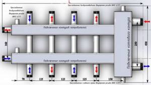
- between the pipes of one circuit a gap of at least 4d must be maintained;
- if the inlet pipes have a diameter of less than 50 mm, then the distance between them should not be less than 200 mm.
There are also completely “outlandish” designs. For example, one craftsman was able to build a hydraulic arrow from two sections of an ordinary cast-iron radiator. This device copes with hydraulic separation without problems. However, this method requires very reliable thermal insulation of the device, otherwise it will result in absolutely unproductive heat losses.
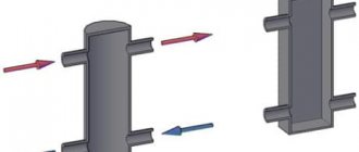
Simply, the operating diagram of a hydraulic needle can be represented as follows. The letters K, N and A denote the boiler, circulation pump and coolant, respectively. The coolant moves through the supply pipes (denoted by red lines) and “processing” pipes (blue lines). At this point the diagram will be ready.
What capabilities are attributed to the hydraulic separator?
Among heating engineers, there are diametrically opposed opinions regarding the need to install hydraulic switches in heating systems. Adding fuel to the fire are statements from manufacturers of hydraulic equipment, promising increased flexibility in setting operating modes, increased efficiency and heat transfer efficiency. To separate the wheat from the chaff, let's first look at the completely baseless claims about the "outstanding" capabilities of hydraulic separators.
The efficiency of the boiler installation does not depend in any way on the devices installed after the boiler connecting pipes. The beneficial effect of the boiler lies entirely in its conversion ability, that is, in the percentage of heat generated by the generator to the heat absorbed by the coolant. No special piping methods can increase efficiency; it depends only on the surface area of the heat exchanger and the correct choice of coolant circulation rate.
Multi-mode, which is supposedly ensured by installing a hydraulic gun, is also an absolute myth. The essence of the promises boils down to the fact that if you have a hydraulic switch, you can implement three options for flow ratios in the generator and consumer parts. The first is absolute equalization of flow, which in practice is only possible if there is no shunting and there is only one circuit in the system. The second option, in which the flow rate in the circuits is greater than through the boiler, supposedly provides increased savings, but in this mode, supercooled coolant inevitably flows through the return to the heat exchanger, which gives rise to a number of negative effects: fogging of the internal surfaces of the combustion chamber or temperature shock.
There are also a number of arguments, each of which represents an incoherent set of terms, but in essence does not reflect anything concrete. These include increasing hydrodynamic stability, increasing the service life of equipment, controlling temperature distribution and others like them. You can also come across the statement that the hydraulic separator allows you to stabilize the balancing of the hydraulic system, which in practice turns out to be exactly the opposite. If in the absence of a hydraulic switch the system’s reaction to a change in the flow in any part of it is inevitable, then in the presence of a separator it is also completely unpredictable.
Real Application Area
However, the thermal hydraulic separator is far from a useless device. This is a hydraulic device and the principle of its operation is described in sufficient detail in specialized literature. The hydraulic arrow has a well-defined, albeit rather narrow, area of application.
The most important benefit of a hydraulic separator is the ability to coordinate the operation of several circulation pumps in the generator and consumer parts of the system. It often happens that circuits connected to a common collector unit are supplied with pumps whose performance differs by 2 or more times. In this case, the most powerful pump creates a pressure difference so high that the intake of coolant by other circulation devices is impossible. Several decades ago, this problem was solved by so-called washering - artificially lowering the flow in consumer circuits by welding metal plates with different hole diameters into the pipe. The hydraulic arrow bypasses the supply and return lines, due to which the vacuum and excess pressure in them are leveled.
Connection diagram and installation
The hydraulic arrow has a connection diagram that is as simple as its own device. Most of the rules relate not so much to the connection, but to the calculation of bandwidth and the location of pins. However, knowledge of complete information will allow installation to be carried out correctly, as well as to ensure the suitability of the selected hydraulic arrow for installation in a specific heating system.
The first thing you need to clearly understand is that the hydraulic arrow will only work in heating systems with forced circulation. In this case, there must be at least two pumps in the system: one in the circuit of the generation part, and at least one in the consumer part. Under other conditions, the hydraulic separator will play the role of a shunt with zero resistance and, accordingly, will short-circuit the entire system.
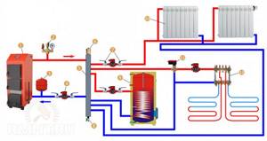
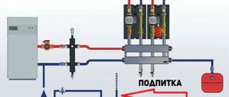
An example of a hydraulic switch connection diagram: 1 - heating boiler; 2 - boiler safety group; 3 - expansion tank; 4 - circulation pump; 5 - hydraulic separator; 6 — automatic air vent; 7 - shut-off valves; 8 - drain valve; 9 - circuit No. 1 indirect heating boiler; 10 - circuit No. 2 heating radiators; 11 — three-way valve with electric drive; 12 - circuit No. 3 warm floor
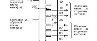
The next aspect is the dimensions of the hydraulic needle, diameter and location of the leads. In general, the diameter of the flask is determined based on the largest calculated flow in the line. The maximum can be taken as the coolant flow rate either in the generation or in the consumer part of the heating system according to the hydraulic calculation data. The dependence of the diameter of the separator flask on the flow is described by the ratio of the flow rate to the flow rate of the coolant through the flask. The last parameter is fixed and, depending on the power of the boiler installation, can vary from 0.1 to 0.25 m/s. The quotient obtained when calculating the indicated ratio must be multiplied by a correction factor of 18.8.
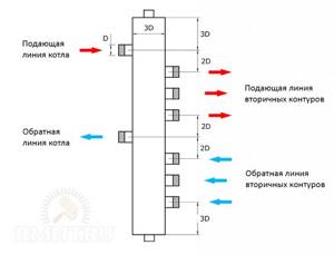
The diameter of the connection pipes should be 1/3 of the diameter of the flask. In this case, the inlet pipes are located from the top and bottom of the flask, as well as from each other at a distance equal to the diameter of the flask. In turn, the outlet pipes are located so that their axes are offset relative to the axes of the inputs by two of their own diameters. The described patterns determine the total height of the hydraulic gun body.
The hydraulic arrow is connected to the direct and return main pipelines of a boiler or several boilers. Of course, when connecting the hydraulic arrow there should not be a hint of narrowing of the nominal passage. This rule forces the use of pipes with a very significant nominal bore in the boiler piping and when connecting the manifold, which somewhat complicates the issue of optimizing the layout of the boiler room equipment and increases the material consumption of the piping.
Types of hydraulic separators
The designs of hydraulic valves can be distinguished, depending on the number of pipes:
- The hydraulic arrow provides 2 circuits (has 4 pipes);
- The KV series hydraulic arrow has 2 pipes on one side, and 8 or 10 outlets on the opposite side;
- A collector water gun (has many pipes on both sides) makes it possible to create a separate heating branch from each pipe and connect its own circulation pump to each branch.
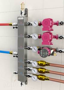
Stainless steel ring manifold with three circuits
Also, the location of the pipes relative to each other can be:
- On one axis.
- With a shift, when the outlet is lower than the inlet (type of alternating pipes).
In the second case, the coolant’s movement speed is slightly reduced, which provides better cleaning from impurities and air. In the first option, the flow accelerates more strongly, but particles can slip into the second circuit.
Devices are distinguished by power and volume. It won’t be difficult to choose the one you need if you have information about the characteristics of the boiler.
Most often, solid fuel boilers are installed forcedly if there is no gas. A solid fuel boiler with a water circuit is the best option for heating a room in the absence of centralized heating.
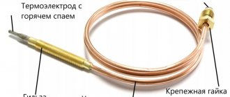
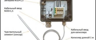
How a thermostat for a heating boiler works and how much such a device costs, read here.
If your house is heated with electrically dependent appliances, you need to consider the possibility of turning off the lights. In order not to lose heat overnight, it is advisable to purchase an uninterruptible power supply for the heating pump. Here https://microklimat.pro/otopitelnoe-oborudovanie/otopitelnye-pribory/besperebojnik-dlya-nasosa-otopleniya.html you will learn all about the features of choosing a device.
Operating principle
A hydraulic switch for heating functions in much the same way as a railway switch.
Only in one case we are talking about the distribution of transport flows, and in the other about the distribution of coolant flows - heated water in heating systems.
The action of this device is to separate the primary heating circuit (boiler circuit) from the secondary one - the heating circuit itself.
The design with a single heating collector suffers from many disadvantages. In particular, with such a heating system, the individual components of the heating system have a rather strong influence on each other, which does not contribute to their normal operation.
Why do you need a hydraulic arrow in a heating system?
A hydraulic arrow is a part from the boiler piping, with the help of which the characteristics of the coolant circulation process are stabilized and thermal fluctuations in the heat-generating unit are leveled out. In addition, the hydraulic arrow can also work as a compensator, ensuring independence of the heating circuits.
As a result, the efficiency of the heating system increases, fuel consumption decreases, the operation of the heat-generating unit is facilitated and the trouble-free operation of all equipment is extended.
How does a hydraulic gun work?
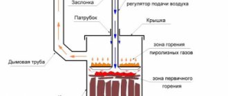
A typical hydraulic arrow is a vertically oriented cylinder or rectangular parallelepiped with four working outlets - two at the top and two at the bottom.
Moreover, the central axis of the upper outlets is located along one line or with one fitting shifted upward. In turn, a pair of lower outlets are arranged either along one axis, or with one of the fittings shifted downward. The pressure branch of the system is connected to the upper branches, and the return branch, respectively, to the lower branches.
The principle of operation of the hydraulic arrow
In addition, a fitting with a valve is cut into the bottom of the housing “arrows” to drain the coolant from the system, and into the lid there is a fitting with a valve to remove air, which accumulates above the water (coolant) and is released due to the pressure in the system.
A hydraulic arrow arranged in this way divides the heating system into two circuits:
- A small branch, which includes the “arrow” and the boiler. Circulation diagram: horizontally from the boiler - vertically along the arrow - horizontally into the boiler.
- A large branch, which includes the boiler, pipes, radiators and arrow. Circulation diagram: horizontally from the boiler, through the arrow, to the battery - vertically along the battery - horizontally from the battery, through the arrow, to the boiler.
Circulation through the small circuit occurs only in the event of excess heat in the system. In this case, the overheated coolant is discharged through the arrow into the return line, after which the boiler temperature controller “extinguishes” the firebox.
In this case, the heat generating unit will be able to start operating the system only after the coolant temperature has dropped to an acceptable level, opening a large circulation branch.
The movement of coolant along a large branch - in fact, the entire wiring of the system - occurs only in the case of normal operation of the boiler, which generates the portion of thermal energy “necessary” for the batteries.
Simply put: a heating system with a hydraulic arrow spends a minimum of fuel and produces a maximum of thermal energy.
How does a hybrid of a hydraulic gun and a manifold work?
Such a hydrodynamic thermostat can be made from any standard arrow by replacing the “right” taps with collectors. That is, opposite each “left” fitting connected to the boiler, it is not the “right” fitting that is welded to the body, but a long pipe with many vertical bends - the heating system manifold.
Hydraulic boom
The coolant flows from the boiler into the “arrow”, moves along it in a horizontal direction and passes into the radiant distribution manifold, distributed over multiple circuits of the heating system. Moreover, each pressure pipe at the “outlet” of the manifold arrow is equipped with its own pump, which ensures the circulation of the coolant in a specific wiring circuit.
As a result, the heating manifold with a hydraulic arrow regulates not only the temperature of the coolant, but also the direction of circulation, equalizing the pressure between the branches of the system. Moreover, the construction of such a hybrid is justified only if it saves space in the boiler room. Since a trivial connection of a pair of manifolds to a standard arrow with four pipes will give the same effect.
How to choose a hydrodynamic thermal separator?
The relatively low price of a hydraulic arrow for heating eliminates the very idea of building this unit with your own hands.
Therefore, most homeowners prefer “factory” switches to homemade ones, choosing a hydrodynamic thermostat according to the following parameters:
- Thermal power of the boiler.
- The volume of coolant in the system.
These parameters must correspond to the “passport” data of the hydraulic arrow, that is, the selection procedure itself is as follows:
- We find out the thermal power of the boiler (from the unit’s passport) and the volume of water in the system (from the length of the pipes and the dimensions of the boiler and batteries).
- We go to the store and buy an arrow that matches the volume and power.
https://youtube.com/watch?v=sLsOysrbhb8
We also recommend watching:
- Film heated floor with infrared radiation
- Alternative heating sources for a private home - what to choose?
- Why is a bypass needed in a heating system?
- Corrugated stainless steel pipes for heating
Specific example of an imbalance in a heating circuit
Suppose we have a heating circuit with 4 circuits, united by a common manifold, and the same number of zone pumps that supply water to the areas of its consumption.
When changing the number of zone pumps or their characteristics, the system will inevitably face the consequences of the mutual influence of each pump on all the others.
This will show up:
- in a drop in the productivity of each pump;
- in breakdowns and premature wear of equipment due to strong pressure drops;
- in a mode of operation of the entire system that differs from the norm. A general decrease in its efficiency, inefficiency and imbalance;
- in overheating of radiators, the temperature of which is higher than normal even when the pumps included in this particular circuit are turned off;
- in the increased likelihood of thermal shock, as well as in other problems that a manifold with a hydraulic arrow is designed to solve.
Read the article about making a hydraulic arrow for heating with your own hands here.
Where can I buy?
Hydraulic distributors are produced here from high-carbon steel with a thickness of 3 mm.
Simple devices with 4 pipes cost from 3.1 thousand rubles. (up to 50 kW). A similar device up to 100 kW will cost almost 4 thousand rubles.
There are models combined with a collector. Such a kit for three circuits will cost 6.8 thousand rubles. Five-circuit – 9.3 thousand rubles. Among the products there is also powerful boiler equipment. For example, a DN100 switch, designed to operate up to 500 kW, will cost 25 thousand rubles.
You can contact the organization by phone +7 913-953-16-80.
Many other manufacturers also produce hydraulic distribution equipment (only the prices are much higher):
- Italian company Immergas;
- Ariston;
- Meibes and others.
Necessity of application
Here are a few examples of heating systems in which the installation of a hydraulic separator (another name for a hydraulic arrow) seems justified:
- If there are several boilers in the system. As an option, we can give an example of a heating system with two boilers: one floor-mounted and the other wall-mounted. Moreover, the need to use a hydraulic gun does not depend on the design and operating principle of the boilers - the main thing is that there are several of them.
- In complex heating systems with one (or several) boiler, but with several consumption zones. Let’s say the water in the system is distributed between a “warm floor” type system, a boiler circuit and several heating radiators. And in this case, you can’t do without a hydraulic gun.
- In simple systems that do not meet the above criteria, the hydraulic separator may not be installed.
Popular manufacturers
There are not as few companies involved in the production of hydraulic separators for heating networks as it might seem at first glance. However, today we will get acquainted with the products of only two companies, GIDRUSS and Atom LLC, since they are considered the most popular.
Table. Characteristics of hydraulic separators manufactured by GIDRUSS.
| Model, illustration | Main characteristics |
| 1. GR-40-20 | — the product is made of structural steel; — designed for one consumer; — minimum power of the heating device is 1 kilowatt; — its maximum power is 40 kilowatts. |
| 2. GR-60-25 | — the product is made of structural steel; — designed for one consumer; — the minimum power of the heating device is 10 kilowatts; — its maximum power is 60 kilowatts. |
| 3. GR-100-32 | — the product is made of structural steel; — designed for one consumer; — minimum power of the heating device is 41 kilowatts; — its maximum power is 100 kilowatts. |
| 4. GR-150-40 | — the product is made of structural steel; — designed for one consumer; — minimum power of the heating device is 61 kilowatts; — its maximum power is 150 kilowatts. |
| 5. GR-250-50 | — the product is made of structural steel; — designed for one consumer; — the minimum power of the heating device is 101 kilowatts; — its maximum power is 250 kilowatts. |
| 6. GR-300-65 | — the product is made of structural steel; — designed for one consumer; — minimum power of the heating device is 151 kilowatts; — its maximum power is 300 kilowatts. |
| 7. GR-400-65 | — the product is made of structural steel; — designed for one consumer; — minimum power of the heating device is 151 kilowatts; — its maximum power is 400 kilowatts. |
| 8. GR-600-80 | — the product is made of structural steel; — designed for one consumer; — minimum power of the heating device is 251 kilowatts; — its maximum power is 600 kilowatts. |
| 9. GR-1000-100 | — the product is made of structural steel; — designed for one consumer; — minimum power of the heating device is 401 kilowatts; — its maximum power is 1000 kilowatts. |
| 10.GR-2000-150 | — the product is made of structural steel; — designed for one consumer; — minimum power of the heating device is 601 kilowatts; — its maximum power is 2000 kilowatts. |
| 11. GRSS-40-20 | — the product is made of AISI 304 stainless steel; — designed for one consumer; — minimum power of the heating device is 1 kilowatt; — its maximum power is 40 kilowatts. |
| 12. GRSS-60-25 | — the product is made of AISI 304 stainless steel; — designed for one consumer; — the minimum power of the heating device is 11 kilowatts; — its maximum power is 60 kilowatts. |
| 13. GRSS-100-32 | — the product is made of AISI 304 stainless steel; — designed for one consumer; — minimum power of the heating device is 41 kilowatts; — its maximum power is 100 kilowatts. |
Let us also note that each hydraulic arrow for heating listed above also performs the functions of a kind of sump. The working fluid in these devices is cleared of various types of mechanical impurities, which significantly increases the service life of all moving components of the heating system.