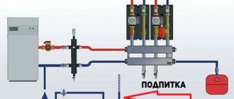
What is a hydraulic arrow in a heating system, device and diagram
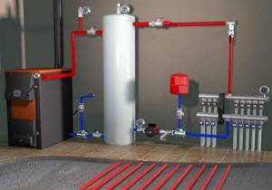
The design of the hydraulic arrow is extremely simple. This is a piece of rectangular or round pipe that has four outlets - two on the side of the boiler circuit and two on the consumer side. Such an element can be placed both horizontally and vertically. Although the second option is more common, since in this case it is easier to install an air vent and a tap to remove sludge that accumulates in the lower part of the structure.
Sectional diagram of a hydraulic arrow for heating systems
Some manufacturers install two meshes inside the hydraulic separator. One serves for air separation, and the other for sludge separation. Although most often such a product is completely empty, since during operation the grids become clogged quite quickly and lose their effectiveness.
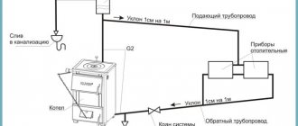
A hydraulic arrow is installed at the break in the connection line between the boiler and the collector, dividing the coolant flow between consumers. Sometimes the hydraulic separator and manifold are assembled in one housing. This simplifies installation and makes the overall design more compact.
An example of a diagram for manufacturing a hydraulic arrow with a manifold in one housing
How she doesn't stop working
The design of this equipment is considered very simple. At the moment, we will not dismantle any very technological devices, but will consider only the key options for implementing this technology.
As a rule, it is enough to use an ordinary piece of pipe from which a hydraulic arrow (hydraulic separator) is made. Calculating the hydraulic arrow will allow you to understand what key characteristics this device should have and what materials are most optimal to use for its manufacture.
Calculation of hydraulic arrow
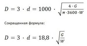
The hydraulic distributor is calculated using formula D to take into account the maximum mode according to the factory parameters of the boiler:
D = 3*d=1000* √ (4*Q)/(π *3600*ω)=18.8*√G/ ω,mm
Calculation of the diameter of the hydraulic valve taking into account the design thermal power of the boiler unit and the temperature difference between the forward and return lines:.
D = 3*d=1000* √ (4*P)/(π *C* ∆T*ω)=17.4*√G/(ω* ∆T), mm
Diameter of the hydraulic arrow pipe for incoming coolant:
d = √ (4*Q)/(π*V), mm
Where:
- D — D of the distributor body, mm;
- D — D of the inlet pipe, mm;
- P is the design heat output of the floor-standing boiler, kW;
- G is the highest coolant flow through the distributor, m3/hour;
- C—heat capacity of water, W/(kg*C);
- V is the speed of water through the CP, m/s;
- Q is the estimated hourly water consumption in KO, m3/h.
Rule one
The most basic rule that must always be followed is, in other words, the “rule of three diameters”, in other words, the diameter of the hydraulic arrow you install must be three times larger when compared with this parameter for the pipes. If you want the hydraulic separator to be able to fully perform its own main functions, in other words:
- separate sludge from the system;
- remove gases;
- equalize the hydraulic difference;
- supply heated water to the boiler to ensure its high durability.
Most people choose to save money and make hydraulic arrows without outside help from polypropylene, but in reality this is a completely wrong decision, made for the most part by people who have little understanding of the specifics of the operation of this equipment.
Actually, because of this, it is worth using exclusively full-fledged metal pipes, which make it possible to fully realize the potential of this technology and will actually demonstrate themselves perfectly throughout the entire operational period of such a system.
How to select parameters
The hydraulic separator is selected taking into account the maximum possible coolant flow rate. The fact is that at high speeds of liquid movement through the pipes, it begins to make noise. To avoid this effect, the maximum speed is assumed to be 0.2 m/s.
Parameters required for the hydraulic separator
By maximum coolant flow
To calculate the diameter of the hydraulic arrow using this method, the only thing you need to know is the maximum coolant flow that is possible in the system and the diameter of the pipes. With pipes everything is simple - you know which pipe you will use for wiring. We know the maximum flow that the boiler can provide (it is in the technical specifications), and the flow rate through the circuits depends on their size/volume and is determined when selecting circuit pumps. The flow rate for all circuits is added up and compared with the power of the boiler pump. A large value is substituted into the formula to calculate the volume of the hydraulic needle.
Formula for calculating the diameter of a hydraulic separator for a heating system depending on the maximum coolant flow
Let's give an example. Let the maximum flow rate in the system be 7.6 cubic meters/hour. The permissible maximum speed is taken as standard - 0.2 m/s, the diameter of the pipes is 6.3 cm (2.5 inch pipes). In this case we get: 18.9 * √ 7.6/0.2 = 18.9 * √38 = 18.9 * 6.16 = 116.424 mm. If we round, we find that the diameter of the hydraulic needle should be 116 mm.
According to the maximum boiler power
The second method is to select a hydraulic needle according to the boiler power. The estimate will be approximate, but it can be trusted. The boiler power and the difference in coolant temperatures in the supply and return pipelines will be needed.
Calculation of hydraulic arrow according to boiler power
The calculation is also simple. Let the maximum boiler power be 50 kW, the temperature delta be 10°C, the diameters of the pipes be the same - 6.3 cm. Substituting the numbers, we get - 18.9 * √ 50 / 0.2 * 10 = 18.9 * √ 25 = 18.9*5 = 94.5 mm. Rounding, we get the diameter of the hydraulic needle 95 mm.
How to find the length of the hydraulic arrow
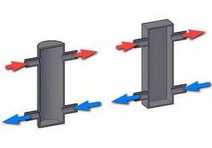
We have decided on the diameter of the hydraulic separator for heating, but we also need to know the length. It is selected depending on the diameter of the connected pipes. There are two types of hydraulic arrows for heating - with taps located one opposite the other and with alternating pipes (located offset from one another).
Determining the length of the hydraulic arrow from a round pipe
It is easy to calculate the length in this case - in the first case it is 12d, in the second - 13d. For medium-sized systems, you can select the diameter depending on the pipes - 3*d. As you can see, nothing complicated. You can calculate it yourself.
Do-it-yourself hydraulic arrow made of steel
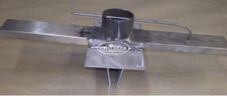
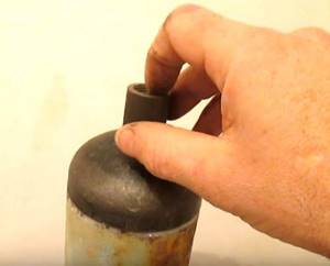
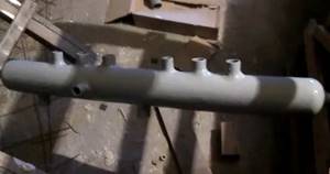
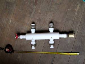
Let’s just say it’s not easy to make a hydraulic arrow from steel according to the found scheme. Working with metal requires certain knowledge and training. Difficulties begin with choosing the appropriate steel grade. Many craftsmen think that any piece of pipe lying around in the garage or storage room will do. This is wrong. After all, the service life of the hydraulic gun and its appearance depend on how high-quality the base is. It is best to take stainless steel or structural steel. Both brands are sold in sheets; working with them is quite difficult for a novice master, so we recommend paying attention to steel pipes. Many installers choose them as a basis. For example, the famous video blogger and repairman Vitaly Luzhetsky from Rostov-on-Don welded a hydraulic arrow from a metal pipe.
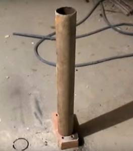
The basis was a pipe with a diameter of 76 mm along the inner circumference
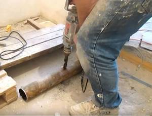
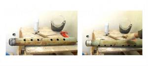
After the inspection, Vitaly began drilling holes to which the threads would later be welded.
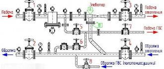
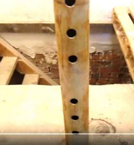
There are eight outputs in total: two for connecting the boiler and three each for supply and return
The author welded the hydraulic gun himself because he couldn’t find a finished product in his city that fit the given parameters. The fact is that the house already had a double-circuit boiler, the performance of which was not enough, they decided to install an indirect heating boiler. It cannot be connected directly to the boiler, so they made an “intermediary”.
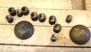
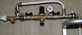
Next, we lay out the components. Threads or “nipples” DN 20 3/4″ with internal edging for welding to inlets and outlets and plugs for end holes.
A 1/2″ thread is also installed on top of the plug for connecting an automatic air vent
Then the welding begins. First they work with the plug bowls.
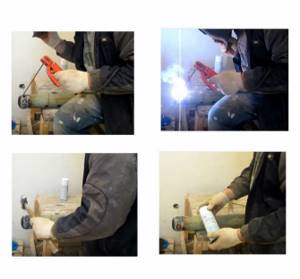
Uneven seams are smoothed out or ground with a grinder. A special composition is sprayed onto the seam to reduce the electrification of the metal.
The photo on the left is a rough draft. on the right - intermediate (the joint is machined)
The next welding step involves installing and attaching the threads. Here you need to pay attention to the accuracy of the diameters.
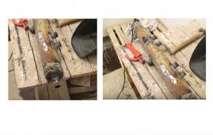
Rough welding does not look particularly aesthetically pleasing, but all flaws can be eliminated at the grinding stage. Particular attention is paid to the junction points (transition areas). If there are a lot of irregularities, additional puttying is carried out. The body of the product is first primed and allowed to dry for several hours.
Also, do not forget about crimping. Usually the arrow is checked before finishing; the permissible range is 10-16 atmospheres. Final painting is carried out only after all preparatory work has been completed. Spray paint was applied at intervals of 15 minutes. Just three layers.

The cost of the product was about 2 thousand rubles.
Why do you need a hydraulic arrow: principle of operation, purpose and calculations
During the operation of an individual heating system, problems arise related to the discrepancy between the volume of consumption and the performance of the boiler. In some modes, it is possible to receive signals from temperature sensors, which will increase the power to maximum values. With simultaneous insufficient media consumption by the secondary circuit, the thermal load will increase excessively. Such situations increase the likelihood of accidents.
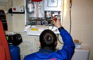
In case of breakdowns, you will need the help of specialists
To describe another situation, it is necessary to assume that the boiler capacity established by the technical passport is 50 l/min. despite the fact that it is necessary to connect heating radiators with twice the consumption. It will not be possible to increase the power so much without placing excessive loads on the equipment.
The next problem is the mutual influence of different types of consumers (warm floors, external boiler, several groups of radiators). For their normal functioning, different volumes and temperatures of coolant are required.
Such problems can be solved using additional sensors and settings. But this will lead to a significant complication of the design and a decrease in the overall level of reliability. In practice, experienced specialists recommend using an elegant engineering solution, which is discussed in detail in this article.
Operating principles of hydraulic arrows in heating systems and main functions
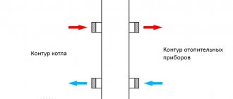
The main purpose of this device is to limit, and ideally, eliminate the hydrodynamic influence of different circuits in the heating system on each other. To do this, use special containers that are inserted into the gap between the two circuits.
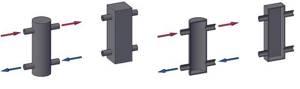
Typical hydraulic arrows in the shape of a cylinder and cube in section
This picture schematically shows a set of equipment with two pumps and connected radiators.
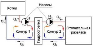
Dual circuit system
Here Q1 and Q2 are the water flow rates in each circuit. If these values are equal, the fluid moves along a common complete contour, as shown in the figure below.

Standard movement along a common contour
The following shows how the passage of fluid changes when the balance in consumption is disturbed:
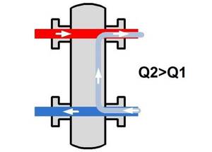
Return flow is greater than supply
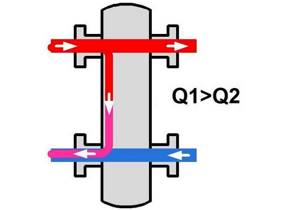
Supply flow is greater than return flow
In order to obtain a hydraulic gun that performs its functions efficiently, the principle of operation, purpose and calculations are coordinated in a special way. It is necessary to create the last option with slow movement of water inside the device from top to bottom. Experts recommend limiting the speed of this process to 0.09-0.12 m/sec. This will help solve the following problems:
- Under such conditions, mechanical impurities will gradually settle at the bottom of the container. If you equip it with a special device, a collector, it will be possible to clean the system during routine maintenance.
- A slow speed will allow the hydraulic arrow to be used to withdraw fluid into other circuits with different temperature gradients.
- It is also useful for accumulating gas bubbles in the upper part of the body. There you can install an automatic air removal device.
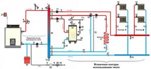
Scheme of using a hydraulic arrow in a complex heating system
Hydraulic heating device
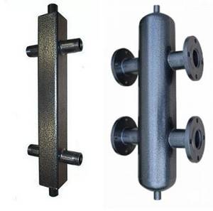
The next picture shows a standard product in this category.
The valve installed at the bottom is designed to drain liquid along with mechanical impurities
Note the special narrowing at the bottom. Contaminants accumulate in it and are not carried further into the system by the flow of liquid. An automatic air release valve is mounted on top
There is an automatic valve mounted on top that releases air.
If necessary, hydraulic arrows are equipped with pressure gauges, valves and other devices
conclusions
In this article we looked at various ways to make a hydraulic arrow with your own hands. The first, steel ones, are widely in demand among specialists due to their wear resistance and functionality. Second, polypropylene arrows are cheaper. However, they are not as reliable as metal ones (they can break due to temperature differences).
The sectional structure of the hydraulic arrow is the same in most homemade products. Hydroshooters produced by specialized companies have a more advanced device. As for the alternative, here again it is worth paying attention to the products of manufacturers. In any case, proceed from your resources and acquired skills, but remember, a free couple of hours can turn into a day or a week.
How is a hydraulic arrow useful?
The need to use the classic hydraulic separator design is obvious. Moreover, on systems with boilers, the implementation of this element becomes a mandatory action.
Installing a hydraulic valve in the system served by the boiler ensures stable flows (coolant flow). As a result, the risk of water hammer and temperature surges is completely eliminated.
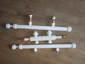
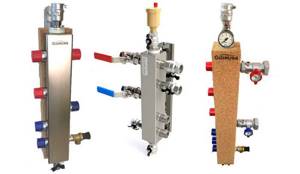
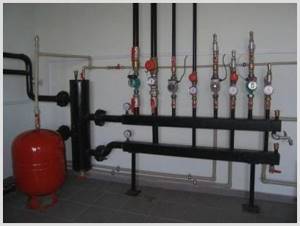
Examples of hydraulic arrows in a classic simple design based on plastic pipelines. Now such structures can be found even more often than metal ones. The operating efficiency is almost the same as that of metal ones, but the fact of savings on the device and implementation in the system
For any conventional water heating system made without a hydraulic separator, turning off part of the lines is inevitably accompanied by a sharp rise in the temperature of the boiler circuit due to low flow. At the same time, the highly cooled return flow takes place.
There is a risk of water hammer formation. Such phenomena are fraught with rapid failure of the boiler and significantly reduce the service life of the equipment.
In most cases, plastic structures are well suited for household systems. This application option seems to be more economical to install.
In addition, the use of fittings makes it possible to install a system of polymer pipes and connect plastic hydraulic arrows without welding. From a maintenance point of view, such solutions are also welcome, since the hydraulic separator installed on the fittings can be easily removed at any time.
Creating parts from polypropylene: features
Boiler parts made of polypropylene can operate at temperatures no higher than 175 degrees. That is why you don’t have to worry that the elements will suffer. You can install a plastic hydraulic arrow.
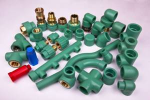
Polypropylene parts withstand high temperatures well
Advantages of installing a hydraulic arrow made of polypropylene:
- Thanks to the smooth walls of the structure, the coolant moves as smoothly as possible. And if the boiler has low power, then rapid movement reduces heat loss.
- Polypropylene can be painted in any color.
- Cheaper option than metal counterparts.
- Resistant to corrosion and deterioration.
- Can work with low power boilers.
But polypropylene hydraulic arrows also have disadvantages. Such products cannot be used for solid fuel boilers. The higher the power of the heating equipment, the less the hydraulic collector will last. Due to high pressure, parts wear out quickly. Installation of the device requires the use of special tools. The quality of the hydraulic connection determines the further operation of the device.
Why do you need a hydraulic arrow: principle of operation, purpose and calculations
Many heating systems in private households are unbalanced. The hydraulic arrow allows you to separate the circuit of the heating unit and the secondary circuit of the heating system. This improves the quality and reliability of the system.
Features of the device
When choosing a hydraulic gun, you need to carefully study the principle of operation, purpose and calculations, and also find out the advantages of the device:
- the separator is necessary to ensure that the technical specifications are met;
- the device maintains temperature and hydraulic balance;
- parallel connection ensures minimal losses of thermal energy, productivity and pressure;
- protects the boiler from thermal shock and also equalizes circulation in the circuits;
- allows you to save fuel and electricity;
- a constant volume of water is maintained;
- reduces hydraulic resistance.
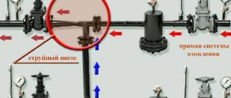
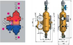
Operation of the device with a four-way mixer
The operating features of the hydraulic switch make it possible to normalize hydrodynamic processes in the system.
Helpful information! Timely removal of impurities allows you to extend the service life of meters, heating devices and valves.
Hydraulic heating device
Before you buy a hydraulic arrow for heating, you need to understand the structure of the structure.
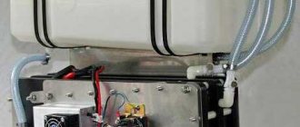
Internal structure of modern equipment
The hydraulic separator is a vertical vessel made of large diameter pipes with special plugs at the ends. The dimensions of the structure depend on the length and volume of the circuits, as well as on the power. In this case, the metal case is installed on support posts, and small-sized products are mounted on brackets.
Connection to the heating pipeline is made using threads and flanges. The material used for the hydraulic arrow is stainless steel, copper or polypropylene. In this case, the body is treated with an anti-corrosion substance.
Note! Polymer products are used in a system with a boiler with a capacity of 14-35 kW. Making such a device with your own hands requires professional skills.
Additional equipment functions
The principle of operation, purpose and calculations of the hydraulic arrow can be learned and performed independently. The new models have the functions of a separator, separator and temperature regulator. A temperature control valve provides a temperature gradient for the secondary circuits. Removing oxygen from the coolant reduces the risk of erosion of the internal surfaces of equipment. Removing excess particles increases impeller life.
Inside the device there are perforated partitions that divide the internal volume in half. This does not create additional resistance.
The diagram shows a sectional view of the device
Helpful information! Complex equipment requires a temperature sensor, a pressure gauge and a line to power the system.
The principle of operation of a hydraulic arrow in heating systems
The choice of hydraulic arrow depends on the speed of the coolant. In this case, the buffer zone separates the heating circuit and the heating boiler.
There are the following hydraulic arrow connection diagrams:
neutral operating scheme, in which all parameters correspond to the calculated values. At the same time, the design has sufficient total power;
Using a heated floor circuit
a certain scheme is used if the boiler does not have sufficient power. If there is insufficient flow, an admixture of cooled coolant is required. When there is a temperature difference, thermal sensors are triggered;
Heating system diagram
the flow volume in the primary circuit is greater than the coolant consumption in the secondary circuit. In this case, the heating unit operates in optimal mode. When the pumps in the second circuit are turned off, the coolant moves through the hydraulic valve along the first circuit.
Option for using a hydraulic arrow
The performance of the circulation pump should be 10% greater than the pressure of the pumps in the secondary circuit.
Features of the system
This table shows some models and their prices.
Construction and equipment
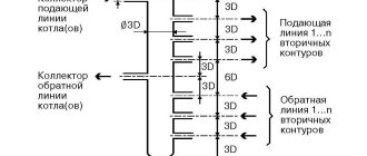
Due to the sharp decrease in the flow rate in the hydraulic arrow, its design and spatial arrangement (true for vertical hydraulic separators), this element is an ideal point in the system for removing air and sludge from the coolant. (We note, however, that not all equipment manufacturers implement such functions).
In Fig. 6
.
The hydraulic pointer VT.VAR.00 is shown (diagram, design and dimensions), supplied by VALTEC as one of the modules of the VARIMIX quick installation system. To remove air accumulating in the upper part of the flask, the separator is equipped with an automatic air vent 1
; a drain ball valve
2
.
The air vent is turned off during repairs or maintenance using ball valve 5
.
To control the temperature and pressure in the supply pipeline of the primary circuit, a thermomanometer 3
4
for the temperature in the return pipeline .
On the supply and return pipes there are also sockets for temperature sensors 6
,
7
(plugged with plugs).
The hydraulic separator body is made of OTS 60Pb2 bronze. The technical characteristics of the module are given in table.
1 .
Rice. 6. Diagram and design of the hydraulic needle VT.VAR.00
Table 1. Technical characteristics of the hydraulic gun VT.VAR.00
| Characteristic | Meaning |
| Working pressure, MPa | 1,0 |
| Test pressure, MPa | 1,5 |
| Maximum temperature of the working environment, °C | 120 |
| Permissible ambient temperature, °C | From 0 to +60 |
| Permissible relative ambient humidity, % | 80 |
| Maximum coolant flow, kg/h | 4500 |
| Maximum connected thermal power (at ΔT = 20 °C), kW | 104 |
| Set weight, g | 4500 |
| Connection to collectors | Fitting VT.0 606 1 1/4 |
| Average total service life, years | 50 |
In 2015, VALTEC announced the release of the VT.VAR05.SS stainless steel hydraulic separator. The choice of body material made it possible to reduce the cost of the product, providing it with high strength and corrosion resistance. At the same time, the developers also improved the design of the hydraulic arrow ( Fig. 7
), supplementing it with a perforated partition to reduce heat loss due to convection of the coolant - from approximately 7 to 2-3%, as well as a spiral perforated separator - for more intensive removal of air from the working environment.
Rice. 7. Design of the hydraulic needle VT.VAR05.SS: 1 – pressure gauge, 2 – drain valve, 3 – automatic air vent, 4 – shut-off valve, 5 – additional threaded pipes, 6 – threaded plugs for additional pipes, 7 – spiral perforated separator, 8 – perforated partition
The hydraulic arrow made of stainless steel is equipped with an automatic air vent with a shut-off valve, a drain valve, and a pressure gauge. Additionally, the housing has connections for a thermometer, temperature sensor, and magnetic sludge trap. The separator is designed for heating systems with operating pressures up to 10 bar and temperatures up to 110 °C. Maximum thermal power at Δ T
= 20 °C – 120 and 200 kW for models with a nominal diameter of 1 and 1 1/4″, respectively.
Operating principle and purpose of the hydraulic gun
- The hydraulic arrow is necessary for hydrodynamic balancing of the heating system and serves as an additional unit. It makes it possible to protect boiler heat exchangers made of cast iron from possible thermal shocks. This can happen during the initial start-up of the boiler, technical checks or maintenance work, which are accompanied by the mandatory shutdown of the heating and hot water supply circulation pump. Also, the use of a hydraulic arrow will protect the integrity of your heating system in the event of automatic shutdown of hot water circuits, underfloor heating, etc. When installing a heating system in your home, in order to comply with the manufacturer’s warranty on the equipment, the installation of a hydraulic arrow is a prerequisite. These requirements are mandatory for boilers whose heat exchanger is made of cast iron. Since, if a large temperature difference occurs between the water at the outlet and the inlet, the destruction of cast iron is possible due to its natural fragility.
- To equalize pressure at unequal flow rates in the main boiler circuit and the total consumption of secondary heat circuits. The hydraulic separator will be useful in the case of multi-circuit heating systems (heating radiators, water heater, hot flooring, etc.). By observing hydrodynamic standards, our device makes it possible to 100% eliminate the influence of circuits on each other and guarantee their uninterrupted operation in specified modes.
- With the correct calculation of the dimensions and hydromechanical parameters, the hydraulic arrow will act as a sump and remove mechanical formations such as rust, sludge, and scale from the coolant. This will significantly extend the operating time of all moving and rubbing elements of the heating system, such as pumps, shut-off valves, meters and sensors.
- The hydraulic separator performs the important role of removing air from the coolant. This will significantly reduce the amount of oxidized metal parts of the heating system.
Purpose of the device
The hydraulic arrow described here is necessary to balance the pressure level in the entire boiler system when the indicators in the main circuit change. Such a device easily regulates the three-circuit version of the system, in which the water heater, the heating radiator, and even the heated floor are turned on at once.
When all the rules of hydrodynamics are observed, stable operation in normal mode is ensured.
It’s worth knowing: most hydraulic arrows are installed in a strictly vertical position so that air is removed from the system completely automatically.
Also, a hydraulic separator is a kind of settling tank in which various types of formations are removed from the coolant, be it scale or corrosion. But this happens again if all hydromechanical standards are met.
It is worth noting that this function of the hydraulic arrow, made of both stainless steel and other materials, increases the service life of many parts in the heating system. Such a device also removes the air formed in the coolant, which reduces the oxidation process in metal parts.
In the classic version of the design, which provides for the presence of only one circuit, if several branches are disconnected, the heat consumption in the system is reduced. Therefore, the temperature of the coolant after passing the entire path decreases slightly. The hydraulic arrow allows you to maintain a stable level of heat consumption, thereby ensuring stable circulation in the system.
Manufacturing schemes
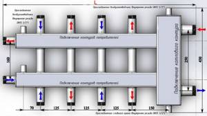
Industrially manufactured water guns are not cheap and many people make them with their own hands. In this case, you need to make preliminary calculations. The main design dimensions are shown in the figure below.
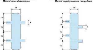
Hydraulic switch diagram with main design dimensions
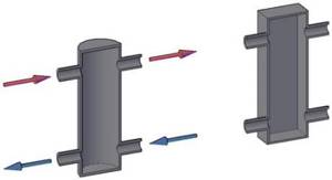
As can be seen from the figure, the diameter of the hydraulic needle itself is taken equal to three diameters of the inlet pipes, so the calculations come down mainly to determining the diameter of the hydraulic needle.
The figure shows two options for hydraulic arrows. The purpose of the second option is better than the first in that when the water passes through the supply pipeline, it is freed from air bubbles, and when it flows back, it better gets rid of sludge.
The calculation comes down mainly to determining the diameter of the hydraulic needle:
Where:
- D – diameter of the hydraulic needle in mm;
- d is the diameter of the inlet pipe in mm, usually taken equal to D/3;
- 1000 – conversion factor meters to mm;
- P – boiler power in kJ;
- π – pi number = 3.14;
- C – heat capacity of the coolant (water – 4.183 kJ/kg C°);
- W – maximum vertical speed of water movement in the hydraulic arrow, m/s, usually taken equal to 0.1 m/s;
- ΔT – difference in coolant temperatures at the inlet and outlet of the boiler, C°.
The calculation can also be performed using the following formula:
Where:
- Q – coolant flow, m³/s;
- V – speed of water movement in the hydraulic arrow, m/s;
There is also the following formula to calculate the diameter of the hydraulic needle:
Where:
- G – flow rate, m³/hour;
- W – water speed, m/s;
The height of the hydraulic arrow can be any and is limited only by the height of the ceiling in the room.
If you make the diameter of the hydraulic arrow large enough, you can get two in one: a hydraulic arrow and a heat accumulator, the so-called capacitive separator.
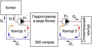
Diagram of a capacitive separator in a heating system
As can be seen from the figure, a hydraulic arrow of this type has a large volume, about 300 liters or more, therefore, in addition to performing its main task, it is also capable of accumulating heat. The use of a hydraulic arrow of this type is especially justified when heating with a solid fuel boiler, as it can smooth out temperature fluctuations in the heating boiler and retain the thermal energy of the boiler after the end of combustion for quite a long time.
You need to know some nuances when using this type of hydraulic arrow:
- Firstly, such a hydraulic arrow must be insulated, since otherwise it will heat the boiler room and not transfer heat to the heating system.
- The boiler will produce less power. This is explained by the fact that a high coolant temperature is required, and the boilers are equipped with automatic equipment that will automatically reduce its power to reduce the outlet temperature.
What is its purpose
First of all, designers are trying to proceed from the fact that the arrow is intended specifically for dividing hydraulics. In most cases, manufacturers are currently trying to produce boilers equipped with their own pumps, and these devices are considered quite powerful.
For example, there are boilers with a closed firebox in which installed pumps are mounted. The power of such devices can be approximately 300 watts, but in reality it will not be enough to completely push through the heating system if it is necessary to provide an object of 1000 m 2, and this equipment is approximately designed for such an average area of the break.
Therefore, it is necessary to install additional pumps, and also use combined systems. Actually, in such a situation, instead of helping, the pump that was originally used in the boiler will simply interfere, and it is in such cases that a hydraulic arrow can be used (purpose, calculation, manufacturing - more on this later in the publication). At the same time, it is necessary to note the point that such high-power equipment, in most cases, is initially supplied with a factory hydraulic arrow in the kit, or at least there are fairly precise instructions on how to connect it.
If you take smaller boilers, then for the most part the story is similar, but in this case you will have to do it yourself.
What is the principle of operation of a hydraulic arrow in a heating system?
The hydraulic arrow can be designated as an intermediary between the boiler or stove and the entire heating system. The operation of the hydraulic separator is as follows:
- The coolant enters the hydraulic separator, changing direction and speed. This is necessary to create a movement in which the hot flow goes up and the cold flow goes down. In turn, this process creates a thermal separation within the water gun for all circuits connected to it. For example, boilers have a high temperature, heated floors have a low temperature, and boilers are characterized by average values of this indicator.
- A high-temperature coolant entering the hydraulic arrow reduces the rate of heat distribution. This leads to the release of air, which must be removed from the heating system using a special valve located at the top of the device. It can be either manual or automatic. A Mayevsky tap is usually used as a manual valve (also called a mechanical valve). In some models, a hydraulic arrow for complex heating systems is installed at the bottom of a faucet to remove dirt and debris.
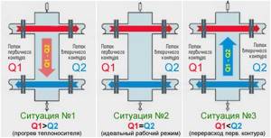
The hydraulic arrow has three operating modes:
Mode 1
In this mode, the heating system works flawlessly. The coolant pressure generated by the pump in the smaller circuit is equal to the total pressure in the remaining circuits of the system. The inlet and outlet temperatures have the same values. The working fluid either does not move vertically at all, or this movement is minimal.
However, as practice shows, ideal work situations are extremely rare. As noted above, the functioning of heating circuits is prone to fluctuations and changes.
Mode 2
In a smaller circuit, the fluid flow is not as high as in the heating circuit. In this case, demand exceeds supply, which leads to the formation of a vertical flow from the return pipe to the supply pipe. During its rise, this flow mixes with hot liquid coming from the heating device.
Mode 3
The situation is absolutely the opposite of mode 2. In this case, the coolant flow in the heating circuits is less than this figure in the small circuit. This happens for several reasons:
- A short shutdown of one or more circuits due to the lack of need for heating any room;
- During the heating process of the boiler, when all circuits are connected in turn;
- Repair of one of the circuits in which this element is disabled.
These situations are not critical, since a downward flow of a vertical direction is formed in the hydraulic arrow.
Advantages of using a hydraulic separator
Installing such a design provides the following advantages:
- “overpressure” of pumps will no longer be a problem;
- overloads are eliminated, and, consequently, the service life of the boiler and equipment increases significantly;
- the boiler will not suffer from corrosion due to low temperatures;
- the consumption of gas used is reduced, since clocking is reduced to a minimum.
In addition to the hydraulic arrow, you can install an expansion tank, and in order to avoid heat loss, it is recommended to insulate the structure with polystyrene foam or any similar material.
A hydraulic separator is required if cast iron radiators and gas boilers are used. Quite often, a separator is a mandatory installation requirement from the manufacturer.
The price of a hydraulic gun is low and pays off many times over. It costs much less than other additional equipment, so it is available to everyone. The decision to install a hydraulic separator must be made at the design stage of the secondary heating circuits. When choosing, you should first of all focus on power; sometimes it is better to take a separator with a reserve. A hydraulic needle can solve many problems that so often arise in heating systems.
Operating principle of the hydraulic separator
The first thing you need to understand is what a hydraulic arrow is in a heating system as a separate element. Structurally, the hydraulic arrow is a hollow device in the form of a pipe with a square cross-section of the profile (read: “The principle of operation and design of the heating hydraulic arrow, purpose”). The simplicity of the design suggests that the operating principle of such a device is quite simple. Thanks to the hydraulic arrow, air is first released and removed from the system, for which an automatic air vent is used.
The heating system is divided into two circuits - large and small. The small circle includes the hydraulic needle itself and the boiler, and in the large circle the consumer is also added to these elements. When the boiler produces the optimal amount of heat, which is completely consumed for heating, the coolant in the hydraulic arrow moves only in the horizontal plane. If the balance of heat and its consumption is disturbed, the coolant remains within the small circuit, and the temperature in front of the boiler rises.
All these actions lead to automatic shutdown of the system, but the coolant continues to move quietly in the small circuit - and so on until its temperature drops to the required value. Upon reaching the set point, the boiler resumes operation in normal mode. All this answers the question of why a hydraulic arrow is needed for heating - it ensures the independent operation of all circuits.
Alternative options
The water gun is sometimes replaced with a bypass or dispensed with, which is important in boiler houses with a small number of consumers. It makes more sense to replace homemade products with products under warranty, that is, hydraulic guns manufactured according to an approved drawing. At first glance, this may not seem financially beneficial.
But here’s how you look: when you set out to do it yourself, bring it to the end. And if you don’t have time, but the desire to make heating in your home according to all the rules has not disappeared, then it is wiser to choose a manufacturer with experience and a good range of models. Our company found one, and it’s great luck that it’s domestic. The Gidruss industrial group has been operating on the market since 2012, and during this time it has taken one of the leading positions in its segment. The brand's product line includes more than a hundred devices designed to ensure optimal distribution of coolant throughout the system. If you want to learn more about the characteristics, see photos or compare prices, welcome to the catalog pages.
Hydraulic flow separation
The hydraulic arrow for heating is more often called a hydraulic separator. From this it becomes clear that this system is intended for implementation in heating circuits.
In heating, it is assumed that several circuits are used, for example, such as:
- lines with groups of radiators;
- underfloor heating system;
- hot water supply through a boiler.
In the absence of a hydraulic arrow for such a heating system, you will either have to make a carefully calculated design for each circuit, or equip each circuit with an individual circulation pump.
But even in these cases there is no complete certainty of achieving the optimal balance.
The classic design of hydraulic separators made on the basis of round or rectangular pipes can be considered approximately this way. A simple but effective solution that radically changes the state of the heating system involving the boiler
Meanwhile, the problem is solved simply. You just need to use a hydraulic separator in the circuit - a hydraulic arrow. Thus, all circuits included in the system will be optimally separated without the risk of hydraulic losses in each of them.
Hydroarrow – the name is “everyday”. The correct name corresponds to the definition – “hydraulic separator”. From a constructive point of view, the device looks like a piece of an ordinary hollow pipe (round, rectangular cross-section).
Both end sections of the pipe are plugged with metal plates, and on different sides of the body there are inlet/outlet pipes (a pair on each side).
The natural appearance of the products is hydraulic switches made from rectangular and round pipes. Both options show high efficiency. However, hydraulic guns based on round pipes are still considered a more preferable option
Traditionally, the completion of installation work on the heating system is the beginning of the next process - testing. The created plumbing design is filled with water (T = 5 – 15°C), after which the heating boiler is started.
Until the coolant is heated to the required temperature (set by the boiler program), the water flow is “spinned” by the primary circuit circulation pump. Circulation pumps of secondary circuits are not connected. The coolant is directed along the hydraulic arrow from the hot side to the cold side (Q1 > Q2).
If the coolant reaches the set temperature, the secondary circuits of the heating system are activated. The coolant flows of the main and secondary circuits are equalized. In such conditions, the hydraulic arrow functions only as a filter and air vent (Q1 = Q2).
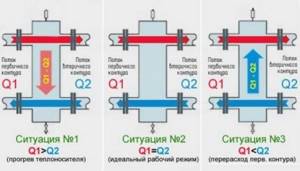
Functional diagram of the operation of a classic hydraulic switch for three different boiler operating modes. The diagram clearly indicates the distribution of heat flows for each individual operating mode of boiler equipment
If any part (for example, a heated floor circuit) of the heating system reaches a predetermined heating point, the selection of coolant by the secondary circuit temporarily stops. The circulation pump is turned off automatically, and the water flow is directed through the hydraulic arrow from the cold side to the hot side (Q1 < Q2).
What hydraulic processes take place in a hydraulic arrow?
In order to understand the reasons for installing a hydraulic separator in the heating system of a house, it is necessary to understand what happens to the water as it passes through the cavity of the hydraulic valve. For these purposes, it is imperative to understand the essence of the basic parameters of the functioning of a properly designed two or more circuit autonomous heating systems using a hydraulic separator.
- After completing the installation work, welding all butt joints in the pipes, the heating system is filled with cool water, usually within 5 - 15 degrees.
- When the boiler is turned on, the automation connects the circulation pump of the main circuit and the burner is ignited, since the coolant has not yet reached the temperature set by the program, the pumps of the secondary circuits do not turn on and the coolant moves only along the primary circuit. Thus, the entire flow will be directed down the hydraulic arrow, as shown in the diagram (Situation No. 1).
- Immediately after the coolant reaches the specified temperature level, an equivalent selection begins by the secondary water flow circuit. In exceptional order, equal water flows of the main and secondary circuits, the hydraulic arrow functions only as an air vent and a dirt-fuel oil trap, that is, as already mentioned above in paragraphs 3 and 4. Thus, the standard heating process and heating of hot water takes place for the needs of your home (in the diagram this is Situation No. 2). It is imperative to pay attention that in practical application it is almost impossible to achieve absolute equality of water flows Q1 = Q2 in all circuits of the heating system. That is why it is imperative to install a hydraulic arrow in the heating system of the house.
- Next, the automation will regulate the flow in the secondary circuit, for example, when the water in the DHW reaches the set temperature, the hot water pump will turn off; in conditions where the thermal heads of the radiators cover the flow due to overheating of the room on the sunny side, thereby increasing the hydraulic resistance in this heating circuit, the automatic adaptive pump is triggered, reducing their performance and reducing the flow Q2. Through this, the flow Q1-Q2 begins to move up along the hydraulic arrow (in the diagram, Situation No. 3). If there is no hydraulic arrow in the heating system, at least the circulation pumps would fail due to significant hydraulic misalignment.
- When the boiler automation stops the pump of the main heating circuit, the coolant flow in the hydraulic arrow tends upward (in the diagram, Situation No. 3). But this situation happens very rarely.
Let's summarize briefly. Considering the above, we can say that installing a hydraulic arrow in the heating system of your home is vital if you have 2 or more heating circuits and the boiler has a cast iron heat exchanger.
How to do it yourself: preparing materials and tools
Self-installation of a hydraulic arrow requires the following applications:
- welding machine;
- hammer;
- angle grinders;
- collector (a steel pipe 80x80 with a wall of 3 mm );
- 2 square washers at the ends;
- 2 threaded components for air release and a tap for draining water;
- two boiler pipes with a thread of 25 mm ;
- 6 threaded parts of 20 mm each for consumers ( 2 for heating, 2 for heated floors, 2 for indirect heating );
- a device for determining the pressure value;
- cranes;
- bimetallic crowns 25 and 29 diameters, drills 8.5 mm ;
- electrodes for welding ( 3 mm );
- primers, hammer paints.
Attention! First of all, it is necessary to check the quality of the parts for the connection . By installing crooked threads, taps and pumps will be damaged.
Primary calculations
To create drawings of hydraulic arrows, you need to correctly determine the size of the pipe.
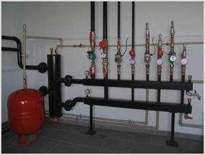
Photo 1. Iron hydraulic needle installed in the heating system. Before installation work, you need to calculate the pipe diameter.
Calculations are carried out using the formula: D=49*vW: ?t, where:
W is the power of the equipment for the boiler room.
?t is the temperature difference.
The length of the collector should be suitable for 6 diameters, and a distance of 2-3 O . Using the data obtained, they draw diagrams of the device assembly.