This publication will discuss the prototype of the bubafoni, the principle of its operation, the procedure for calculating the main parameters and how such a stove can be built even from auxiliary materials.
Expert opinion: Afanasyev E.V.
Chief editor of the Stroyday.ru project. Engineer.
The name “bubafonya” sounds somewhat unusual to the ignorant reader, but meanwhile the popularity of this stove is very high. This is also explained by the fact that the design of its structure is quite simple, and the bubafon itself can be classified as a long-burning stove that uses fuel economically and does not require its constant addition to the firebox.
It is not only residential premises that require heating in private households. Many owners cannot imagine a single day without working, for example, in a workshop or garage, and in winter, without local heating, these buildings will be very uncomfortable. Heating may also be necessary in homestead farming - greenhouses, premises for pets and poultry.
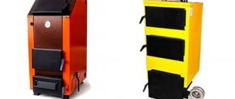
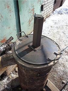
Do-it-yourself bubafonya oven
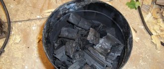
Conducting a heating circuit from the house into such buildings is extremely difficult and wasteful. It is better to provide for the installation of stoves that can be heated as needed with solid fuel - firewood, sawdust, coal, etc. There are many options for such heating devices, and many of them are economical and easy to use. Stoves can be purchased in stores, but a good owner can always make one himself. One of these common crafts is to bake a bubafonya oven with your own hands.
Basic principles of operation of the Bubafonya stove
The name “bubafonya” comes from the online nickname “bubafonja”, which belongs to the Russian master Afanasy Bubyakin from distant Kolyma. It is not known whether he was the first to create a home-made stove of a similar design, but it was his model, the experience of assembling which he shared on the Internet, that became a kind of “hit”, a basis for imitation, a basis for many home craftsmen for their own developments and improvements.
According to the majority, the prototype for such a development was the design of the Lithuanian long-burning boiler, which gained wide popularity among Russian homeowners.
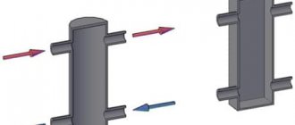
The prototype of bubafoni is most likely “Strоpuva”
Stropuva boilers are produced in a fairly wide range of models, from S7 to S40 (the number indicates the heating power in kilowatts). However, all are characterized by a special shape - a narrow elongated vertical cylinder. This is not a whim of the designers - such a structure is determined by the very principle of operation of this long-burning boiler. The solid fuel loaded into it is ignited and burns from top to bottom. This is achieved by the fact that the air necessary for the oxidation process is supplied only to the thin top layer of the charge.
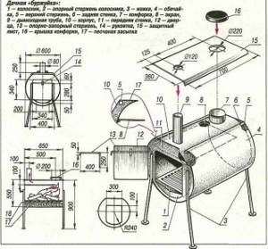
The diagram shows a schematic diagram of the Stropuva boiler.
Schematic diagram of the long-burning boiler "Strоpuva"
- The combustion chamber (8) is loaded with solid fuel (firewood, sawdust, coal, briquettes) through a special window (6).
- Ignition of the top layer is usually carried out using flammable liquids. Then the air distribution device (7) is lowered onto this layer. It can be cross-shaped with special deflectors to supply air to a certain depth of the burning layer.
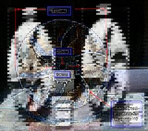
Cross-shaped gas distributor of the Stropuva boiler
There are models with a distributor in the form of a crossbar, and recently disc-shaped ones have become widely used - who knows, maybe this was already borrowed by the designers of Stropuva from the Bubafoni, since such an innovation was introduced after its promulgation her diagrams.
- In order for the furnace to operate stably, the supplied air needs certain preparation - heating to approximately 400 ºС. This process takes place in a special chamber (2). In the same chamber there is a special mode switch - a damper (4) with the “coal” or “firewood” positions.
- The heating chamber is connected to the air distributor by a telescopic tubular channel (5), which extends as the combustion zone descends.
The telescopic air supply channel is clearly visible
- The combustion intensity is controlled by a damper (1), which regulates the amount of air entering the combustion zone. In the case under consideration, this happens automatically - a bimetallic spring is installed, changing its configuration depending on the heating temperature
- Since “Strоpuva” is designed specifically for a heating system, a heat exchanger (water jacket) with return pipes (11) and heated water outlet (10) is provided.
- A hatch (9) is mounted in the lower part of the housing for inspection and cleaning of the boiler from residual combustion products.
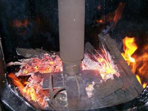
Surface combustion process
The combustion of the upper layer of fuel with a dosed intake of air leads, in addition to direct heat transfer, to the release of pyrolysis gases, the afterburning of which, after the boiler enters normal operation, is carried out in the upper part of the cylinder, above the air distributor. After this, the exhaust gases are discharged into the chimney opening (3).
In fact, the boiler turns out to be a combined boiler, combining simultaneously the processes of direct combustion of fuel, pyrolysis and afterburning in one closed volume.
A Russian craftsman tried to implement a similar scheme. The main problem was the complexity of manufacturing a telescopic supply unit and air distribution device in the burning layer. However, a very original solution was found.
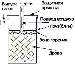
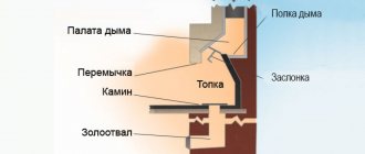
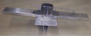
Approximate diagram of the structure of the bubafoni stove
- The very complex air distributor was replaced by a massive disk - a “pancake”, from the lower part of which deflectors made of a metal profile - channel or corner - were welded. This creates channels for the most uniform distribution of gas over the surface. This “pancake” with its mass presses the burning layer, and under the influence of gravity it gradually lowers as the fuel is consumed.
- Now about the air duct. It was not made telescopic, but one-piece, from one piece of pipe, welded to the “pancake” of the air distributor. Thus, the air intake channel itself also gradually lowers - a kind of piston with a rod moving in the cylinder is obtained. For the free movement of the air pipe, a hole of the appropriate size and shape is cut out in the top cover of the stove, so that it does not impede the free movement of the entire structure, but at the same time does not leave an excessively large gap for air to “suction” from the outside.
Too tight an obturation, by the way, is not required in this place - a certain amount of oxygen must also enter the upper chamber of the stove - this is what is necessary for the afterburning of pyrolysis gases.
The developer of this stove preferred the air duct pipe with a square cross-section
The lid is made in such a way that it fits as tightly as possible to the cylindrical body of the bubafoni. The air flow is regulated by a damper installed at the end of the air duct.
An outlet pipe is welded into the upper part of the housing to allow combustion products to exit, which is connected to the chimney pipe.
So, the scheme is very simple and seemingly uncomplicated - you can make a stove from any available materials. So it is, in principle, but if you approach this issue with the utmost seriousness, and in order to achieve the highest indicators of efficiency and heating power, you should focus on the recommendations for calculating such a heating device.

Heat resistant paint
Prices for the linear range of heating boilers Stropuva
Heating boilers Stropuva
Lighting Features
The kitchen light is positioned so that no shadow falls on the worktops when cooking. Otherwise, damage to the eyes is caused. Also, devices should not be too bright so as not to dazzle. Manufacturers provide a backlight built into the headset, which is convenient and practical. If the furniture does not have such a function, an LED strip is installed above the tabletop. You can place it on the kitchen apron or around the perimeter of the furniture. The distance from water sources to lamps must be at least 60 cm.
The lighting on the dining table is soft and cozy. If the table is located against the wall, use several wall sconces; if near the window - a table lamp or floor lamp. Devices without shades look impressive - they fit perfectly into any style.
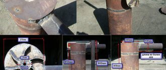
Do-it-yourself bubafonya oven - calculating the main parameters
The dimensions of the main parts and assemblies that directly affect the operational characteristics of the furnace are shown in the diagram.
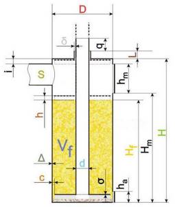
Basic parameters of the correct bubafoni stove
If you cannot find ready-made drawings for the manufacture of such a device, then you need to arm yourself with a calculator and carry out some calculations yourself.
1. The dimensions of the stove , that is, the diameter of the body ( D) and its height (H) , must lie in a certain proportion. The optimal ratio is considered to be from 1: 3 to 1: 5. Engineering thermal calculations show that in a stove that is too narrow, the incoming air simply leaves the combustion zone and is thrown into the chimney, which results in a significant loss of power of the unit. If you make the stove too wide, then it is difficult to achieve good results closer to the walls of the combustion body. Only the central part of the fuel filler will burn out, the pancake in this place will definitely sag and jam, and the combustion process will stop. The optimal furnace diameters are from 300 to 800 mm.
2. Δ – body wall thickness . This parameter is especially important if you plan to “dress” the stove in a water jacket, thereby turning it into a boiler. In this case, you should focus on a thickness of 4 to 6 mm.
In the case where the stove will only serve for local heating of the room by direct heat transfer, the wall thickness can be lower; bubafoni are often made from ordinary metal barrels. However, this necessarily leads to a loss of power - thin walls of a large area cause a drop in temperature above the “pancake” and the effective afterburning of pyrolysis gases may be lost or significantly reduced. In addition, hot gases in the bubafon leak through a fairly narrow gap between the “pancake” and the walls, exerting a strong thermal effect on them, which is why thin sheet metal can quickly burn out. However, if you use metal of about 2.5 mm, for example, if the body is bent from a whole sheet, then this thickness will be quite enough to heat a garage or workshop.
3. Parameters of the air distribution device . It is a mistake to believe that they are limited only by the diameter of the cut “pancake” - its thickness is also important, since this part must have good heat capacity - it is in this area that the final heating of the supplied air is carried out.
So, for starters, the diameter of the disk. Calculations show that the optimal gap between it and the stove wall will be C = 5% D. For example, if the internal diameter of the housing cylinder is 400 mm, then a gap of 20 mm is required on each side, and we get a “pancake” Ø 360 mm.
The thickness of the pancake ( σ ) in practice is inversely proportional to its diameter. An excessively heavy unit will simply sink into the combustion zone, extinguishing the fire, while a unit that is too light will not create reliable pressure. And this may end in ignition of all the fuel or even reverse combustion; for years, the flames will come out through the supply air pipe, and the flow of air will go through the chimney.
The approximate thickness of the steel “pancake” is given in the table:
| Furnace cylinder inner diameter (D) | Thickness of the pancake workpiece (σ) |
| 300 mm | 8 ÷ 10 mm |
| 400 mm | 6 ÷ 8 mm |
| 60 mm | 4 ÷ 6 mm |
| 800 mm | 2.5 ÷ 4 mm |
The height of the ribs of welded air ducts (channels, angles or steel strips). There is no clear linear relationship here, but you can focus on the following values.
| Furnace cylinder inner diameter (D) | Air duct fin height (h) |
| 300 mm | 40 mm |
| 400 mm | 50 mm |
| 600 mm | 60 mm |
| 800 mm | 80 mm |
If a cylinder of a different diameter is being manufactured, then the thickness can be easily calculated proportionally, bringing it, of course, to the standard thicknesses of manufactured metal sheets.
Optimal configuration of distribution channels
However, if you want to make a truly efficient stove, then it is better to make them in the form of blades curved in a clockwise direction - the air path in this case increases, improving the uniform combustion of fuel on the surface, and, in addition, a directed turbulent flow appears, which contributes to the most complete combustion of pyrolysis gases. The design of the air channels created is also important. The simplest thing is a cross-shaped arrangement of channels with side shelves of the required height.
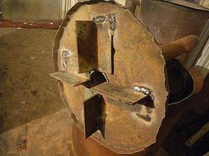
And this is a completely unsuccessful example of making an air distributor
And this is an example of what should never be done. The edges of the “pancake” are not processed, the metal is very thin, and the corner shelves, on the contrary, are extremely high. In essence, the entire effect of bubafoni is lost - most likely, such a part will lead to extensive combustion of the fuel filler.
4. The next most important characteristic is the diameter of the chimney outlet , or more precisely, its cross-sectional area (in the diagram - S ) .
This parameter is calculated by professionals using rather complex formulas that take into account many characteristics. However, practical experience in using such furnaces allows us to somewhat simplify the calculation procedure, and the calculations can be carried out independently.
Basic formula: S=1.75 E
— S – cross-sectional area of the chimney pipe.
— E – energy output of the stove per unit time (kW/h).
E itself is determined by the following formula: E=M × e.
— M is the mass of fuel added to the stove.
— e – specific heat transfer of a particular type of solid fuel.
The mass of the filling is calculated based on the volume of the working part of the stove and the weight coefficient of the fuel type, i.e. its specific mass per unit volume.
M = Vf × mf.
— Vf – volume of the fuel compartment of the stove (dm³).
— mf – fuel loading coefficient (kg/dm³).
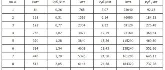
Indicators e and mf are reference values. As an example, these data for some common types of solid fuel are given in the table:
| Type of solid fuel | mf – specific loading factor, kg/dm³ | e – specific heat transfer, kW/h |
| standard size firewood, aspen | 0,143 | 2,82 |
| pine shavings or sawdust | 0,137 | 3,2 |
| alder pellets | 0,285 | 3,5 |
| DPK grade hard coal | 0,4 | 4,85 |
| SSOM grade coal | 0,403 | 5,59 |
| coarse anthracite | 0,5 | 5,72 |
| peat briquettes | 0,34 | 2,36 |
For example, you can take the calculation of the chimney cross-section for a homemade bubafoni from a regular gas cylinder, which has D = 300 mm, H f = 600 mm. One more value remains - the volume of the loading chamber. Its height (in the diagram - Hf ) is usually taken as ⅔ of the total height of the stove H. The volume is calculated using the usual formula - the cross-sectional area of the cylinder multiplied by the height: Vf = πD²/4× H f.
Vf = π × 3² × 6: 4 = 42.39 ≈ 42 dm³.
The calculation of thermal characteristics always follows the fuel that will give maximum heat transfer. In this example, let’s take SSOM coal:
Total mass of stove loading with coal: M = 42 × 0.403 = 16.92 ≈ 17 kg.
Burning such a mass of fuel in an hour will produce the following amount of energy:
E = 17 × 5.59 = 95.03 – can be rounded up to 100 kW.
Thus, the cross-sectional area of the chimney for the stove in question is required:
S = 1.75 × 100 = 175 cm². From here it is easy to calculate the diameter of the pipe - in this case it will be 14.93 cm or, when reduced to the standard pipe size, 150 mm.
By the way, such calculations can also give an idea of what the average power of the stove will be. In our case, 100 kW was received. Practice shows that with a properly assembled unit, it works on one load for about 12 hours. Thus, we get 100 / 12 = 8.33 kW/h.
5. Basic parameters of the air supply pipe. Its diameter ( d in the diagram ) with some strengthening can be taken as 0.5 ÷ 0.55 from the diameter of the outlet pipe. Thus, in the example under consideration, a 76 or 80 mm pipe can be used.
The pipe will be welded into the “pancake” of the air distributor. It is recommended that its lower edge be placed at the same level as the lower edges of the air guides. To avoid excessive air flow in the center, which can create an unnecessary cone-shaped zone of intense combustion, the outlet hole of the pipe can be narrowed, for example, by welding here an unnecessary steel gear with a narrow mounting hole, and the main air flows can be redirected between the blades (channels). This way the distribution of air masses will be more even.
Expert opinion: Afanasyev E.V.
Chief editor of the Stroyday.ru project. Engineer.
Most home craftsmen sin by limiting themselves to cutting out a hole in the stove lid for the air duct pipe, without installing any collar. Meanwhile, such a simplification of the design results in a significant reduction in the efficiency of the bubafoni, since excess “parasitic” air sucked in from here reduces the completeness of afterburning of pyrolysis gases and forms a steady flow towards the chimney, without ensuring the required heat exchange. In a word, part of the heat simply goes into the pipe through a draft. But installing the collar is not difficult at all.
How to calculate the parameters of this node?
— The gap between the pipe and the collar ( δ ) should be no more than 2.5 mm.
— The collar height ( L ) must be at least 80 × δ .
— With the “piston” completely lowered down, the air duct pipe should rise above the upper cut of the collar to a height of q = L + 150.
In our example we get the following:
- Let's say that after making a collar cylinder (usually they are made from galvanized sheet) and trying it on a pipe, pressing it to one side, we get a clearance of 2.4 mm. Thus, the created gap δ is 1.2 mm on each side.
- Based on this, the collar height ( L) should be at least 1.2 × 80 = 96 mm.
- The part of the pipe protruding above the collar is q = 96 + 150 = 246 mm.
Of course, the obtained values can be rounded up, to 100 and 250 mm.
On the upper section of the pipe, it is necessary to consider a movable damper, which, moving around its axis, will be able to operate in the full range - from completely closing the pipe lumen to completely opening it. It is this damper that will be the main “control element” of the stove - it regulates the amount of air supplied to the fuel combustion zone.
If the stove is planned to be multi-fuel, then a similar damper is often installed on the top cover of the stove. To burn pyrolysis gases emitted by some types of fuel, an additional “portion” of air may be required.
6. Additional parameters of the bubafoni stove. These parameters, in principle, do not determine the operational characteristics of the stove, but they must be taken into account at least so that the bubafonya is most convenient for everyday use and maintenance. These include:
- The distance from the top edge of the stove body to the insert of the chimney pipe and the loading door (in the diagram - i ).
Calculated using the formula i = h + σ + 20 mm. (the meaning of all symbols has already been mentioned in the text above).
- The height of the lower edge of the loading door from the lower edge of the cylinder (in the diagram - Hm ).
Hm = Нf + h + σ + 30 mm
This makes it possible to inspect and periodically clean the lower surface of the “pancake” from soot deposits.
- Based on the calculations performed, it is easy to determine the height of the loading door:
hm = H – Нf – i.
In this case, the width of the opening should not be more than ¼ of the circumference of the stove body cylinder.
- It is also necessary to provide a technological door for cleaning the stove from combustion waste (ash pan). It must be wide enough, since when coal is used as fuel, caked slag can accumulate at the bottom of the cylinder, which can be removed by pipe.
The door height ( ha ) is calculated as follows: ha = h + σ + 100÷150 mm.
The width of the opening is the same as that of the loading door.
Expert opinion: Masalsky A.V.
Editor of the “construction” category on the Stroyday.ru portal. Specialist in engineering systems and drainage.
To avoid air leakage through the doors (hatches), they are made in two layers with a mandatory seal made of asbestos sheet or basalt cardboard. The opening itself is framed with a box-shaped neck, onto which the hatch hinges are welded.
Welded box on the neck of the stove cleaning hatch
By the way, many performers generally refuse any kind of hatches in their designs. In this case, both loading and cleaning of the stove is carried out through the top with the lid removed and the “piston” removed. There are fewer maintenance conveniences, but the work of making bubafoni is greatly simplified. To somehow facilitate the loading and cleaning process, handles are welded to the stove lid.
7. Bubafoni installation parameters. When drawing up your own design for a bubafoni stove, you should definitely calculate the main parameters of its future installation and connection to the chimney pipe.
The basic principles are shown in the diagram, however, a few more clarifications should be given:
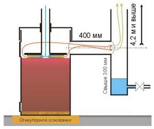
Approximate installation diagram for the stove - bubafoni
- It doesn’t matter whether such a stove will have welded legs, or whether it is simply planned to be placed on the lower end part, the base must have pronounced fire-resistant qualities. The combustion of fuel in the stove-bubafon goes all the way to the lower boundary of the cylinder, and the bottom, of course, becomes very hot from this. An ordinary concrete screed will not suit you in any way - crumbling and cracking will certainly begin soon. This means that you will need to build a kind of “podium” from refractory fireclay bricks.
- The height of the chimney pipe must be at least 4.2 m, otherwise the quality of draft will decrease, which will result in a sharp decrease in heat transfer due to the defective process of afterburning pyrolysis gases in the secondary chamber - the stove will simply “suffocate”.
- The size of the horizontal section of the chimney, before inserting into its vertical part, should be no more than 400 mm. It is also not recommended to bring it too close - the thermal equilibrium of the system may be disrupted.
- The pyrolysis process is always accompanied by a fairly significant release of water vapor, even in the case of well-dried firewood. To avoid the accumulation of water condensate on the inner walls of the chimney (and this sometimes even leads to complete freezing of the pipe openings), a special elbow should be provided - a moisture collector. Its height from the insertion point is at least 300 mm. A drain valve must be installed at the bottom for regular maintenance - draining accumulated liquid. It is better to install a ball valve - this will make it possible to clean the clogged drain hole with a piece of thin wire.
Perhaps, for some, such calculations for the bubafoni stove may seem overly cumbersome. However, this is not at all difficult - it’s worth devoting a few evening hours to such a process, armed with a calculator, and your own project, based on an almost scientific approach, will be ready. But you won’t have to doubt the performance of the heater in trouble.
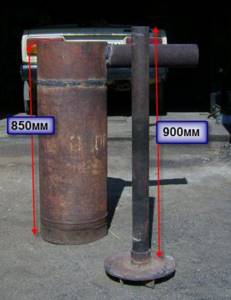
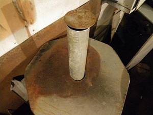
By the way, you can even start from materials available in the household. The publication already mentioned an old gas cylinder - this is an almost usable blank for the body.
Bubafonya stove made from a gas cylinder...
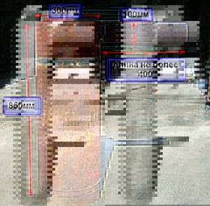
Knowing the parameters of this cylinder, it will be easy to “adjust” all other parts and components to it.
... and its dimensional parameters
Housing and air supply and distribution device
And finally, the oven assembly
If you have good skills in working with metal and the ability to use sheet-bending equipment, then you can create your own project “from scratch”, with exactly the dimensions and power required to heat a particular room.
Prices for sheet metal bending machines
Plate bending machine
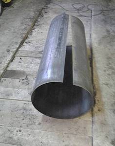
You can also make a bubafon from a metal sheet, exactly according to your calculated dimensions
Video: bubafonya stove from a gas cylinder
Tools and materials
Let's talk a little about the materials used. If you want to assemble a Bubafonya stove with a water jacket with your own hands, make sure that the thickness of the walls of the combustion chamber is 4-6 mm. The jacket is made in two ways - by scalding the main body with sheet iron to form a heating circuit, or by wrapping it with a metal pipe. If the stove will heat the premises directly, then the thickness of the walls does not matter much - an old barrel will do just fine, but without through corrosion.
As for the tools and auxiliary materials needed to assemble the Bubafonya stove, we will need:
The most dangerous part of the work associated with making a stove is, of course, everything that involves an angle grinder. When using it, you need to be as careful as possible.
- Welding machine – for cutting and welding individual elements;
- Grinder (angle grinder) – for cutting and processing metal edges;
- Hacksaw for metal – for working with small elements;
- Pipes of the diameter indicated on the drawing;
- Condensate drain valve;
- Hammer;
- Sheet metal 2-3 mm thick.
We have five stages of assembling the Bubafonya stove:
- Preparing the installation site;
- Working with a barrel (gas cylinder);
- Preparation of the pressure circle;
- Chimney preparation;
- Assembly and first launch.
Let's go through these stages in more detail.
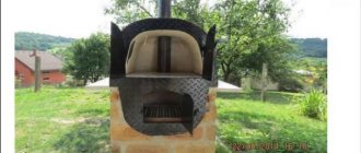
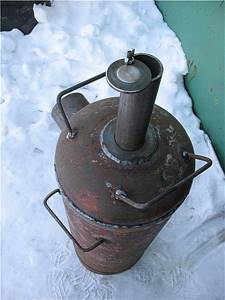
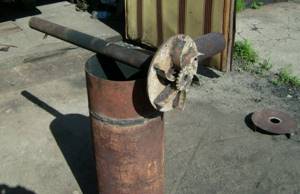
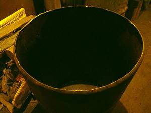
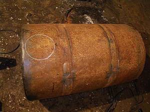
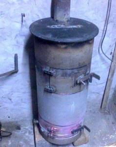
One of the simplest options is bubafonya from a barrel
And finally, a little about how you can make a simple bubafonya from such a common auxiliary material as an unnecessary metal barrel, which, however, has retained the integrity of the walls.
The thickness of the metal of the barrels is small, and, of course, it will not be possible to obtain too significant heat transfer from such a bubafon. Its efficiency is also not very significant, but a large loading volume and a working time on one “refueling” of up to 12 hours are what is needed for heating some outbuildings or utility rooms.
Another convenience of this design is that the barrels have a single standard size. If the most vulnerable area, the walls, burns out (which is bound to happen sooner or later), it will not be difficult to quickly make a replacement, since the remaining parts - the cover and the air supply system, which are less susceptible to rapid wear, can easily be rearranged into a new housing.
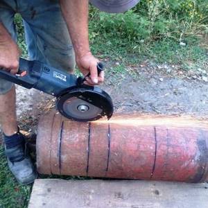
So, first of all, you need to remove the top cover of the barrel. It is best to carefully cut the weld seam around the circumference with a grinder - and the cylinder will have a smooth edge, and the lid will have a flared “skirt”.
Prices for popular brands of portable welding machines
Portable welding machine
It is best to cut off the weld between the cylinder and the barrel lid
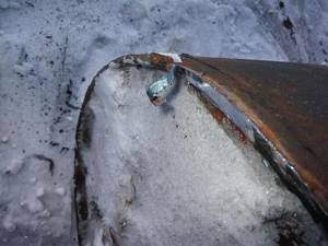
The edges of the barrel are driven slightly inward with a sledgehammer, and on the lid, on the contrary, the lining is expanded.
The edges of the body are processed...
...and the cut off lid
As a result, the lid should fit tightly on top of the body.
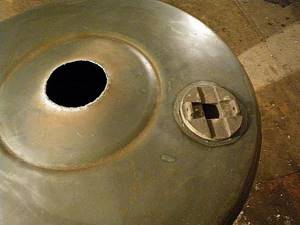
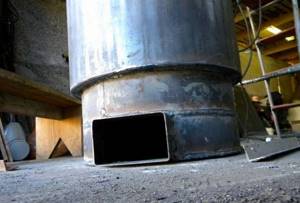
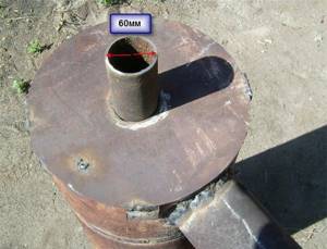
Hole for moving the air duct pipe
If there is a plug on the lid, it can be scalded, but often this hole is left for a second air damper.
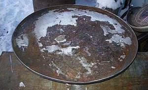
The lid can be made a little differently. In this case, it is cut to such a diameter that it fits snugly into the housing cylinder. A metal plate of arbitrary size and shape is welded on top - it will become both a support and a kind of “slab” on which you can put a kettle or a bucket to heat water.
A hole is cut in the center of the prepared lid to match the diameter of the air supply pipe. You must try to keep the edges as smooth as possible.
The lid can also serve as a kind of stove for heating water.
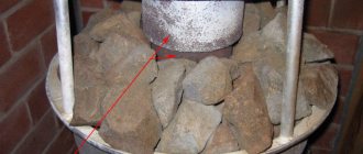
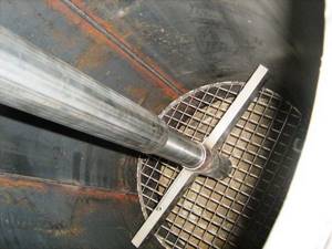
The air distribution device is being prepared. Usually for it they take the same lid from another barrel or cut out a blank from a metal sheet. If a sufficiently thin-walled metal is used, it is recommended, if possible, to make bends downwards around the circumference - this will reduce the risk of deformation of the disk during strong heating. A round hole is cut in the workpiece where the air supply pipe will be welded.
Metal profiles – air ducts – are welded from the bottom of the “pancake”. The figure shows a channel, but with such a large diameter of the stove, it is still preferable to choose the option with curved blades made of a metal strip - the air distribution process will be much more efficient. This, of course, will require more time, but it is worth spending it to increase the productivity of the furnace.
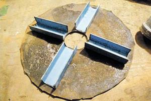
Air distribution channels made of channel
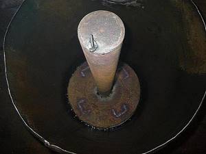
The resulting “pancake” is welded to the air supply pipe.
Damper at the end of the supply pipe
An air damper mounted on the axle is attached to the top of the air supply pipe. For ease of operation, it is recommended to provide for fixing the position of the damper in the desired position, for example, with a wing nut.
A more advanced damper - with a locking “wing”
A hole is marked on the stove body for inserting the chimney pipe.
Marking the hole for the outlet pipe
When welding a chimney pipe, be sure to ensure complete sealing of the seam.
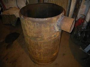
The chimney pipe is welded to the body
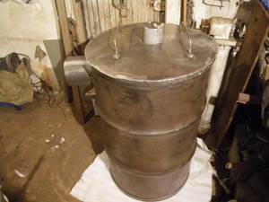
In fact, all bubafoni nodes are already ready. unless, of course, you count the chimney. All that remains is to assemble the stove by installing the “piston” of the air supply system into it and closing the structure with a lid.
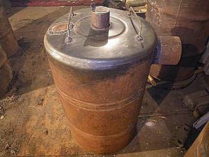
Bubafonya from a steel barrel is ready
As already mentioned, for convenience, you can weld the handles both to the lid and to the stove body itself.
Video: version of the bubafoni stove from a barrel
If you wish, you can “dress” the bubafon stove in a protective metal screen, which is mounted on short stands welded to the body.
Another option is to wrap the body with a profiled sheet with a sufficiently high wave height. In both cases, this will have a double positive effect:
- The risk of getting an accidental burn from the hot stove body will be significantly reduced.
- This design will create a powerful convection flow, which will help quickly warm up the room.
The screen will protect from burns and create a good convection flow.
The designs discussed in the article are basic, and each master can make his own changes in compliance with the basic fundamental parameters. There is a very wide field for creativity and experimentation here. For example, in the presented video, the author shares his own improvement of bubafoni:
Video: how you can improve a typical bubafonya stove
Features and types of homemade stoves from a gas cylinder
All solid fuel stoves made from a gas cylinder have common design elements:
- A housing in which holes are cut for the door, vent and exhaust pipe.
- Blower.
- Exhaust pipe equipped with a throttle valve.
- A grate located low above the bottom of the stove. Fuel is placed on it and its combustion occurs.
- Internal walls that form the flow of combustion products.
- Legs.
Potbelly stove design
Through the door, fuel is loaded and ash and slag are removed from the grate space. An air flow enters the combustion chamber through the blower and the combustion mode is adjusted. The blower is made as a structural part of the door or is made in the form of a separate hole with a damper. A throttle-type damper is installed into the exhaust pipe, which also regulates the combustion mode. Gas cylinder stoves are available in vertical and horizontal versions. A horizontal oven is easier to implement, but takes up a lot of space. The vertical one can be placed in any corner of the room; it has significantly better draft and fuel combustion efficiency.
Vertical oven from a gas cylinder Horizontal oven from a gas cylinder
In liquid fuel furnaces (they are also called oil or drip furnaces), instead of a grate, a burner of one design or another is fixed and a fuel supply pipeline is installed. The door is much smaller - it is not needed for loading fuel and removing ash and slag, but only for adjusting the air flow, as well as for installing and servicing the burner.
To the basic configuration of a gas cylinder stove, a home craftsman can add various improvements: a burn-protection guard, burners for heating and preparing food and drinks, hangers for drying clothes and shoes, etc.
Fuel tank
The container where the fuel will be placed will be made from a metal barrel.
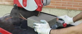
1. Make markings and cut off the top of the barrel. To do this, we use either a hacksaw or a grinder.
To cut with a grinder, you will need a metal cutting disc. The size of the grinder does not matter
When working, it is important not to apply excessive force to the tool.
Metal jigsaw
If there is no ready-made barrel, then the container is constructed from sheet steel. But for this you will need additional tools: a manual sheet bender, a sheet bending machine or a blank, with which you can give the sheet the shape of a cylinder.
Sheet steel oven container
To bend a sheet with a manual (roller) bender, one edge is fixed with a pressure beam, then the sheet is rolled to the required radius.
After the sheet is rolled into a cylinder, the seam is welded using a welding machine. To do this, install grounding on a sheet of metal and weld the edges, preventing the electric arc from going out. By the way, we have an excellent tutorial on our website on how to cook with electric welding. If you maintain the same distance between the part and the electrode, the seam will be straight and even.
When the cylinder is ready, the bottom is cut out from a piece of sheet steel according to the markings using a grinder and welded.
When the fuel tank is ready, markings are made in the upper part for the outlet pipeline. It is convenient to make markings with a can of paint or a pencil. Using the markings, a grinder is used to cut out a hole to which the pipe is welded. This pipe will connect to the piping of the space heating system.
Marking for the outlet pipeline