Areas of application of heating combs
The main purpose of the heating comb is to optimize and rationally distribute the coolant.
Without a correctly designed and installed distribution manifold, the heating may not operate correctly. The comb allows you to use all the useful power of the boiler, while obtaining maximum efficiency of the entire system. Collectors also allow you to include several consumer points in the system and be sure that the temperature of the coolant in all sections of the main will be the same. If you do not use a distribution comb, it often turns out that the radiator near the boiler is very hot, and the radiator, for example, on the second floor, is lukewarm.
This happens because the coolant cools down while it reaches the last battery. This effect can be avoided and the path of the coolant to the end consumer can be reduced by dividing it into specific circuits.
Calculation of comb throughput
The calculation of the parameters of the distribution comb includes determining its length, the cross-sectional area of its cross-section and pipes, and the number of heat supply circuits. It is better if the calculations are done by engineers using computer programs; in a simplified version, they are only suitable at the preliminary design stage.
In order to maintain hydraulic balance, the diameters of the inlet and outlet manifold combs must match, and the total throughput capacity of the nozzles must be equal to the same parameter of the collector pipe (the rule of total sections):
n=n1+n2+n3+n4,
Where:
- n is the cross-sectional area of the collector4
- n1,n2,n3,n4 - cross-sectional areas of the pipes.
The choice of comb must correspond to the maximum thermal output of the heating system. What power the factory product is designed for is written in the technical data sheet.
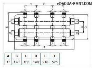
For example, a distribution pipe diameter of 90 mm is used for a power not exceeding 50 kW, and if the power is twice as high, the diameter will have to be increased to 110 mm. This is the only way to eliminate the risk of unbalancing the heating system.
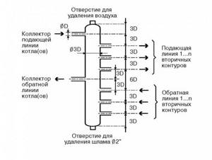
The cross-section of the collector pipe is equal to 3 diameters of the connected pipes, the distance between the supply and return combs is 6 diameters, the distance of the pipes from each other is 3 diameters
The 3-diameter rule is also useful (see picture above). As for calculating the performance of the circulation pump, the specific water consumption in the heating system is taken as the basis.
Each pump is calculated separately - per circuit and for the entire system. The figures obtained in the calculation are rounded up. A little extra power is better than too little.
Pros and cons of collector systems
The main advantage associated with the use of collector-type systems is the ease of control and operation. This is due to the fact that each of the elements can be controlled both centrally and individually. Consequently, it is possible to set the temperature for each specific room, and, if necessary, completely deactivate a device or group of devices. Moreover, this will not affect other parts of the system.
Video – Collector heating system
Each of the branches that make up the node must power only one battery (or, alternatively, a separate group of batteries), so the diameter can be insignificant. If necessary, using a collector, you can equip several circuits with different temperature parameters at once. This became possible thanks to the advent of a hydraulic arrow - a type of comb, which is a similar tube, but of a larger diameter.
This arrow is installed differently from a standard manifold - a kind of short circuit is created in the gap between the “return” and the supply. The liquid in the initial circuit will be permanently heated by the boiler and smoothly move inside the hydraulic arrow, as a result of which different temperature and coolant pressure indicators are demonstrated.
But there are, of course, disadvantages. First of all, buying a distribution comb is a very expensive pleasure and this is probably the only reason why these devices scare away potential buyers. The fact is that high-quality steel is used in the production process, which is why the products are much more expensive than steel pipes. In addition, for installation you will also need high-quality shut-off valves (the number of them depends on the number of circuits).
Another drawback is the mandatory presence of a circulation pump, without which the comb simply will not be able to function (read: additional electricity costs).
Planning stage
To make the correct manifold for a heating system, you must have the following data:
- The number of circuits that will be connected to the node.
- An exact list of heating devices from which the heating system will be assembled, as well as their technical characteristics.
- List of additional devices that need to be equipped with a heating system. This may include pumps, fittings, buffer tanks, thermometers, pressure gauges, etc. It is important to clearly determine the model of the device, since you need to know its connection parameters.
- At least a rough plan for the future regarding system improvement: what equipment and in what quantity are you going to connect in the future? Today, devices that allow the development of alternative heat sources are becoming increasingly accessible and efficient, so it is possible that soon you will want to retrofit your system with a heat pump or solar collector.
Based on these data, it is possible to calculate the comb parameters: diameter, length, number and dimensions of bends.
A two-story house is very high-status, cozy and beautiful. But such a house must be well heated. Heating diagram for a two-story house - an overview of the types of heating systems and installation tips.
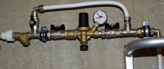
Is it necessary to install a boiler safety group? Read on. Elements included in the system.
What you need to know about the cons?
After the advantages of using distribution combs in heating systems have become clear, it makes sense to dwell on some of the disadvantages:
- High price. Collectors are made of durable, high-quality metal, the cost of which is above average. High-precision locking equipment is also expensive. The more circuits a comb serves, the higher the cost of equipping it.
- Energy dependence. Collector heating without a circulation pump does not work. Therefore, you need to prepare for additional payments for electricity.
- High pipe consumption. The consumption of pipes in collector heating systems is several times higher than in conventional ones, since a separate loop must be pulled to each device. All this complicates and increases the cost of installation work.
The collector system, according to experts and those who already use it, is the most modern, reliable and efficient.
But at the same time, both its arrangement and operation are expensive.
Rules for connecting the distribution comb
The selection of the collector location must be based on the principle of equidistant location of the equipment from it. If this requirement is neglected, then high pressure arises at more extended nodes of the system, which will negatively affect this area. Therefore, the permitted difference in lengths of pipe sections from the comb to the batteries should not violate the 1:2 proportion.
Or, in other words, the length of the pipelines from the first radiator to the collector and subsequent batteries cannot be less than 2 times. If the specified characteristics are exceeded, it will not be possible to ensure accurate operation of the comb. If the house has many floors, the collector is installed on each of them. There are a number of methods for placing the distribution comb in the heating system: in a special installation cabinet or directly on the wall.
When installing the collector on the walls, specialized niches are made in them. To install the heating comb, determine a place above the floor level. In terms of dimensions, the niche must correspond to the dimensions of the comb, taking into account attachments and piping of heating pipelines. The space where the collector is located must certainly be dry. Usually, for these purposes, a corridor or an auxiliary room is chosen, where the distribution system will not disturb anyone.
In case the distributor is located in a transition, it is recommended to place a special metal cabinet with a door and holes for the input/output of pipelines in a niche. This design is usually equipped with special fasteners to securely fasten it.
Areas of application of heating combs
The main purpose of the heating comb is to optimize and rationally distribute the coolant. Without a correctly designed and installed distribution manifold, the heating may not operate correctly. The comb allows you to use all the useful power of the boiler, while obtaining maximum efficiency of the entire system.
Collectors also allow you to include several consumer points in the system and be sure that the temperature of the coolant in all sections of the main will be the same. If you do not use a distribution comb, it often turns out that the radiator near the boiler is very hot, and the radiator, for example, on the second floor, is lukewarm.
This happens because the coolant cools down while it reaches the last battery. This effect can be avoided and the path of the coolant to the end consumer can be reduced by dividing it into specific circuits.
How to adjust the comb?
In order for the water heated floor to provide a comfortable temperature in all rooms, the distribution unit must be pre-configured. The system is regulated according to 2 parameters of the coolant:
The first parameter is set on the three-way mixing valve. This can be done manually by setting the required water temperature by turning the adjustment wheel. But more often, the circuit involves a thermostatic head with a remote sensor and a capillary tube, so the water temperature must be set on it. The sensor is tightly attached to the manifold.
Quantitative adjustment of the comb can be done either manually or automatically. By rotating the cap on the valve of each circuit and looking at the flow meter readings, you should achieve the calculated water flow, if you know it. If not, then you will have to adjust it by feel within a few days.
Automatic adjustment involves replacing the caps of special servo drives that remotely interact with thermostats in all rooms. Then the comb with the pump will supply as much coolant to the heating circuits as is needed at the moment. Servo drives on all taps will control the flows at the command of the thermostats.
What is a hydraulic arrow
If pumping equipment of significant power is installed in a multi-circuit complex heating system, then even it will not be able to cope with the different conditions and parameters of the network operation. Such inconsistencies in the operation of different circuits will negatively affect the operation of the heating boiler and shorten the service life of expensive equipment.
Branched heating networks cannot work harmoniously due to the fact that each circuit has its own performance and pressure. But even if each circuit is equipped with its own circulation pump, taking into account the parameters of the main line, the problem of system fragmentation will only worsen. This will lead to unbalancing of the networks, because each heating circuit will have its own parameters.
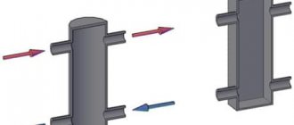
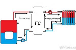
To solve the problem, one common boiler must heat the required amount of coolant, but each circuit must receive the required amount of heated liquid from the collector. In this case, the functions of the hydraulic system separator are performed by the manifold. A hydraulic separator is needed to separate the boiler flow from the general circuit. Another name for a hydraulic separator is a hydraulic arrow or HS (hydraulic arrow).
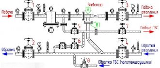
The name of the device comes from the analogy with a railway switch. Just as a railway switch directs trains in the required direction, a hydraulic switch distributes coolant flows across separate circuits. Externally, the device resembles a piece of round or rectangular pipe with end caps. The device is connected through a pipeline to the collector and boiler and has several pipes in the side.
The most popular models
1. Oventrop Multidis SF.
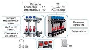
An inch heating comb is designed to organize heating with a water heated floor. Made from tool steel, characterized by high wear resistance. Main characteristics:
- permissible pressure in the circuit – 6 bar;
- coolant temperature – +70 °C.
The series is produced with valve inserts M30x1.5, and can also be equipped with a flow meter for connecting circuits located in different rooms. A bonus from the manufacturer - soundproofed mounting clamps. The number of simultaneously serviced branches is from 2 to 12. The price, accordingly, is 5650-18800 rubles.
To work with high-temperature appliances, Oventrop suggests using a heating system distribution manifold made of Multidis SH stainless steel with a Mayevsky tap. The design can already withstand 10 bar at +95-100 °C, the comb throughput is 1-4 l/min. However, products with 2 circuits have slightly weaker performance. The cost of Oventrop SH hydraulic valves ranges from 2780-9980 rubles.
Plumbers: You'll pay up to 50% LESS on your water bills with this faucet attachment
- HKV – brass underfloor heating manifold. Maintains a pressure of 6 bar in the range of +80-95 °C. Rehau version D is additionally equipped with a rotameter and a tap for filling the system.
- HLV is a heating distribution comb designed for radiators, although its characteristics are identical to the description of HKV. The only difference is in the configuration: a Eurocone is already provided here and the possibility of a threaded clamp connection with pipes.
The manufacturer Rehau also offers to buy separate Rautitan combs with three outlets for pipeline installation using sliding sleeves.
Heating distribution manifold made of steel with anti-corrosion coating. It operates in systems with temperatures up to +110 °C at a pressure of 6 bar and is hidden in a special heat-insulating casing. The throughput of the comb channels is 3 m3/h. Here the choice of designs is not very rich: it is possible to connect only from 3 to 7 circuits. The cost of such hydraulic valves will range from 15,340 to 252,650 rubles.
Stainless steel manifolds are produced in an even more modest range - for 2 or 3 circuits. With the same characteristics, they can be purchased for 19,670-24,940 rubles. The most functional Meibes line is the RW series, which already comes complete with various connecting elements, thermostats and manual valves.
- F – a flow meter is built into the supply;
- BV – has quarter taps;
- C – provides for extension of the comb through a nipple connection.
Each Danfoss heating manifold allows a system pressure of 10 atm at an optimal temperature (+90 °C). The design of the brackets is interesting - they fix paired combs with a slight offset relative to each other for more convenient maintenance. Moreover, all valves are equipped with plastic heads with marked markings, which allows you to set their position manually without the use of tools. The price of Danfoss models, depending on the number of connected circuits and additional options, varies between 5170 - 31,390.
The heating manifold can be selected for a Eurocone with 1/2″ or 3/4″ outlets or with a metric threaded connection. Far combs can withstand pressure up to 10 atm at temperatures not exceeding +100 °C. But the number of outlet pipes is small: from 2 to 4, but the price is the lowest of all the products reviewed in our review (730-1700 rubles for an unpaired distributor).
Tips for choosing
Despite the apparent simplicity of the combs, they need to be selected based on several technical parameters:
1. Pressure in the system - this value determines what material the distribution manifold can be made from.
2. The throughput must be sufficient so that the connected heating circuits do not “starve” from a lack of coolant.
3. Energy consumption of the mixing unit - as a rule, it is determined by the total power of the circulation pumps.
4
Possibility of adding circuits - this parameter should be paid attention only when in the future it is planned to build additional objects that require heating
The number of pipes on the hydraulic distributor must correspond to the number of connected branches (heating devices). In some cases, it is better to install several collectors, for example, in a two-story house - one block on each level. It is also possible to install unpaired combs at different points: one on the supply, the other on the return.
Finally, experts and experienced installers in their reviews advise not to skimp on buying a good collector. In order for it to serve for a long time and not cause any problems, the name on the box must be known.
Connection rules and installation features
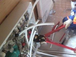
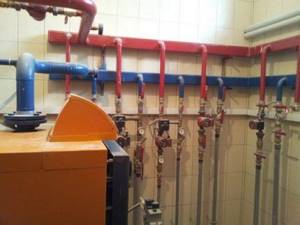
Installation of the comb begins with attaching it with brackets to the wall, where it will be located openly or in a closet. Then you will need to attach the main pipes from the heat source to the ends and begin piping.
Option #1 – without additional pumps and hydraulic arrows
This simple option assumes that the comb will serve several circuits (say, 4-5 radiator batteries), the temperature is assumed to be the same, and its regulation is not provided. All circuits are connected directly to the comb, one pump is used.
The characteristics of pumping equipment must be correlated with the performance of the heating system and the pressure created in it. So that you can choose the best pump that is ideal in terms of characteristics and cost, we recommend that you familiarize yourself with the rating of circulation pumps.
A master with experience in manifold equipment knows how to correctly install a distribution comb and hide it in a cabinet so as to hide all the pipes
Since the resistance in the circuits is different (due to different lengths, etc.), it is necessary to ensure optimal consumption of the coolant by balancing.
To do this, balancing valves, rather than shut-off valves, are installed on the return comb nozzles. They can regulate (although not exactly, but by eye) the coolant flow in each circuit.
Option #2 - with pumps on each branch and a hydraulic arrow
This is a more complex option, which will be needed if necessary to power consumption points with different temperature conditions.
So, for example, in radiator heating, water heating ranges from 40 to 70 °C, a warm floor needs a range of 30-45 °C, hot water for domestic needs must be heated to 85 °C.
In the piping, the hydraulic arrow will now play a special role - a section of pipe that is blind at both ends and has two pairs of bends. The first pair is needed to connect the hydraulic needle to the boiler; the distribution combs are connected to the second pair. This is a hydraulic barrier that creates a zone of zero resistance.
On the comb itself there are mixing units equipped with three-way valves - temperature control devices. Each outlet pipe operates its own pump independently of the others, providing the specific circuit with the required amount of coolant.
The main thing is that the total power of these pumps does not exceed the main boiler pump.
Both options considered are used when installing distribution manifolds for boiler houses. Everything you need is sold in specialized stores. There you can buy any assembly assembled or element by element (counting on savings due to self-assembly).
To further reduce future costs, you can make a heating distribution comb yourself.
The boiler room manifold is located in close proximity to the heating equipment and is exposed to high temperatures that only metal can withstand.
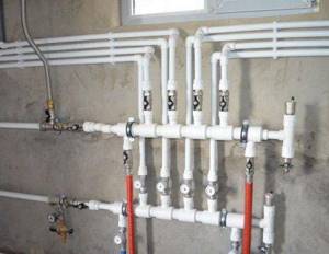
The local distribution comb is subject to less stringent requirements for heat resistance; not only metal pipes, but also polypropylene and metal-plastic pipes are suitable for its manufacture.
For a local distribution manifold, the easiest way is to select suitable scallops from those that are commercially available. In this case, you should take into account the material from which they are made - brass, steel, cast iron, plastic.
Cast scallops are more reliable, eliminating the possibility of leakage. There are no problems connecting pipes to the manifolds - even the most inexpensive models have threads.
Distribution combs assembled from polypropylene parts are attractive due to their low cost. But in an emergency, the joints between the tees will not withstand overheating and will leak
Craftsmen can solder a manifold from polypropylene or metal-plastic, but they will still have to buy threaded tips, so the product will not be much cheaper in terms of money than a ready-made one from the store.
Externally, it will be a set of tees connected to each other by tubes. The weak point of such a collector is insufficient strength at high heating temperatures of the coolant.
The comb can be round, rectangular, or square in cross-section. Here, the transverse area comes first, rather than the cross-sectional shape, although from the standpoint of hydraulic laws, rounded is preferable. If the house has several floors, it is better to install local distribution manifolds on each of them.
How to build a collector yourself?
You can buy a ready-made connection, choosing one that would approximately meet the needs of your home. But achieving an exact match is quite difficult. Therefore, it is better to make a heating comb yourself. Let's figure out what is needed for this.
Planning stage
There are a number of parameters of the heating system of the house that you should know when building a unit.
- The number of circuits through which heated water will pass.
- The number and technical characteristics of the heating equipment included in the scheme.
- Additional equipment involved in installation. This refers to pressure gauges, thermometers, taps, storage tanks, valves, pumps, etc.
It is also necessary to provide for the possibility of increasing the load if over time it is necessary to build in elements that were not taken into account in advance. This could be, for example, solar panels or a heat pump.
It is necessary to foresee in advance not only the number of circuits operating in the heating system, but also additional equipment that will be included in the overall scheme
Determining the block design
The design of the future node depends on the connection point of each circuit. After all, there are some connection nuances that cannot be ignored.
- Boilers (electric and gas) must be connected to the comb from above or below.
- The circulation pump should be connected from the end of the structure.
- Solid fuel units and indirect heating boilers also need to be cut in from the end.
- The supply circuits of the heating system are connected from below or from above.
For clarity, it is necessary to make a drawing of the future compact and neat unit. This will help determine the quantity and types of materials we will need. All necessary dimensions and threaded connections with thread pitch are also applied to the drawing. All circuits should be marked to guide the drawing when connecting.
This drawing shows a four-way manifold. You may not make a drawing and will limit yourself to a sketch, but do not forget to put on it all the dimensions necessary for the work
The distance between the nozzles of both combs should be from 10 to 20 cm. These are the optimal parameters for maintenance. The distance between the supply and return combs themselves should be within the same limits.
Sequence of work
To make both combs, not only round, but also square pipes can be used. The sequence of work performed is as follows:
- In full accordance with the parameters indicated on the drawing, we purchase all the necessary materials.
- According to the drawing, we make the connection by welding pipes, taking into account their subsequent functions. Welding areas should be cleaned with a wire brush and degreased.
- Testing a homemade unit is a necessary stage of work. To do this, all pipes are hermetically sealed except one, through which hot water is poured into the system. Let's take a good look at all the joints: they shouldn't leak.
- Now the collector can be painted and dried thoroughly.
- Next, you should connect pipes, locking mechanisms and control equipment to it.
After this, the device is ready for use. This will differ favorably from purchased products in that it is built taking into account the needs of a particular home, and this is very important for its further operation. Of course, a high-quality and functional device can only be obtained if the master knows how to handle a welding machine and metalworking tools.

In order for a homemade collector block to work more efficiently than a purchased one, the master needs to be able to handle both welding equipment and plumbing tools
You can learn how to make a polypropylene manifold by watching this video:
Operating principle of the collector system
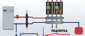
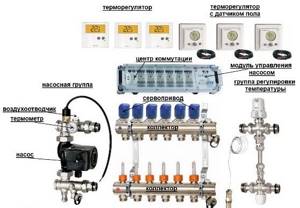
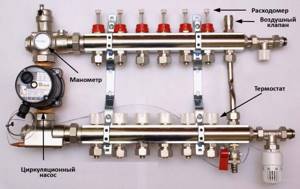
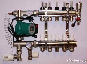
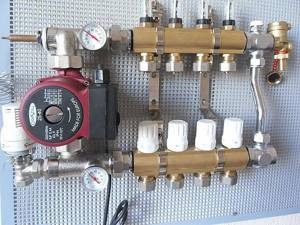
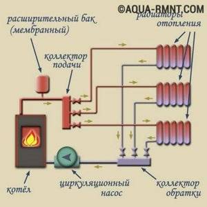
The manifold is a metal comb with leads for connecting pipes and devices. The collector heating system is two-pipe. Hot water is supplied through one comb, and pipes that collect cooled water (return) are connected to the other.
The collector heating system has a closed expansion tank and a circulation pump that moves the coolant. The minimum volume of the expansion tank is equal to at least 10% of the total volume of all heating devices. The pump is installed on any of the pipelines leading to the collectors.
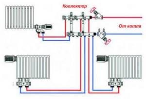
The collectors are installed in special cabinets, which are mounted in wall niches or in a separate room. The collector cabinets should be located at approximately the same distance from each heating device. Pipes can be connected to radiators from above, from the side and from below. The most widespread is the lower pipe connection to radiators. This option provides the best opportunity to hide pipes in the floor. A shut-off valve is installed on each hydraulic circuit coming from the collector, which makes it possible to turn off any radiator without disturbing the operation of the heating system. A valve is installed on each radiator to release accumulated air - a Mayevsky valve, or on the manifold - air release valves. Heat meters and drain valves can also be installed on the collector.
Each hydraulic circuit located after the manifolds is an independent system. This made it possible to create heated floors. These are floors in which pipes are laid in parallel or in the form of spirals, which heat the floor surface. The pipes are laid on a heat-insulating pad, connected to the collector and, after checking the tightness of the pipelines, they are filled with concrete. The height of the screed should not exceed 7 cm. The laying pitch and diameter of the pipes are determined by calculation. The length of one heating spiral should not exceed 90 m. Basically, metal-plastic pipes are used for heated floors, which easily accept any curvature.
When heating a warm floor, the temperature decreases according to the height of the room, and when installing radiators, on the contrary, the higher, the warmer.
Operating principle of the distribution manifold
In modern heating systems, two types of distribution manifolds are used - for boiler rooms and local. They have different dimensions and a slightly different operating principle.
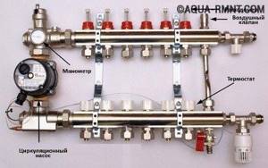
In the boiler manifold, the supply comb supplies coolant to the parts of the heating system, so it is equipped not only with taps, but also with circulation pumps. The second comb is the receiving one.
In addition, pressure and temperature sensors and a very important element - a hydraulic arrow - are installed on the manifold. It maintains an optimal temperature difference between supply and return.
The boiler manifold is a distribution unit of quite impressive size; its combs are made of pipes with a diameter of up to 100 mm and above
The local distribution comb differs from the central manifold installed in the boiler room, both in size and operating principle. There may be several of them in a heating system.
If in the main collector the cooled water is completely replaced by hot water from the boiler, then in the small combs the circulating water is diluted.
The coolant in them moves in a closed circle until its temperature drops below a predetermined level.
Compliance with the temperature regime is monitored by a sensor, which, when the temperature drops critically, opens a valve that blocks the path of water from the boiler main. Hotter water enters, mixing with the cooled water.
A fully equipped local comb with regulators, an air release device, a pump, a pressure gauge, and thermometers allows you to fully control the movement of coolant in the heating system
There is no hydraulic arrow in such collectors; it is replaced by an additional circulation pump. It pushes the coolant in a circular space, periodically throwing in a portion of hot water from the supply line. In this case, the same amount of cooled water is returned there, but into another pipe - the return pipe.
Local combs are used both in heated floors and for connecting radiators.
Since the water in the heating pipes with a distribution manifold moves forcibly under the influence of the pump, the system will not work if the power is turned off
To achieve highly efficient functioning of the heating system throughout the house as a whole, it is recommended to build into it both a central distribution manifold and the required number of local combs. Together they will give the desired result.
Advantages of a collector heating system
The main advantages are the ease of control of the design, in particular:
- Each circuit element can be controlled independently and centrally. This means that in the house the owner sets the temperature of each room and has the opportunity to turn off the radiator or group of radiators from heating altogether.
- Reduced costs. Due to the supply of coolant to only one battery, smaller diameter pipes are suitable for forming a pipeline. Plus the ability to disconnect the battery from the heat supply - together you get some good savings. The liner is most often recessed into the screed, taking into account the minimum distance from the boiler and radiator.
- You can set up several circuits with different heating parameters, including temperature changes, using a hydraulic arrow.
Also, when installing a collector for a heating system, you need to take into account the disadvantages:
- increased energy consumption;
- difficulties in equipping beam distribution and recessing devices into the screed;
- increased hydraulic resistance in the system.
When arranging independent heat supply to different circuits, it becomes necessary to use circulation pumps for each circuit, which means that the system becomes energy-dependent.
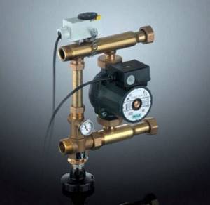
Principle of operation of the collector
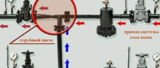
The main purpose of the device is to uniformly supply heat flows from the main line along the circuit circuits and to the heating radiators, as well as to supply return water to the boiler. The device acts as an intermediate distribution unit and consists of a supply and return comb. In this case, the supply element is responsible for supplying coolant to the circuit, and the return element is responsible for returning the liquid to the boiler.
From each comb there are leads for connecting circuits leading to heating devices. The distribution comb of the heating system with leads can be supplemented with shut-off valves, which help regulate the pressure inside the circuits and, if it is necessary to carry out repairs or reduce the heating intensity, shut off the coolant supply to a separate branch.
The principle of operation is simple - a thermal collector for heating a house transfers coolant through a supply comb to the circuits, while inside the intermediate unit the coolant circulation rate is reduced due to the increased internal diameter of the structure, and this ensures uniform redistribution across all outlets.
The coolant is directed through connecting pipes, enters separate circuits and is transported to heating radiators or to a heated floor grid. Then the structure is heated, and the liquid is redirected through another pipe to the collecting comb of the collector. From here the water flows to the heat generator.
Operating principle and functionality
The main function of the flow meter is to ensure adjustment of the coolant along the circuits. The presence of rotameters allows:
- Control the heating of the liquid, which makes it possible to save energy;
- Ensure uniform heating of all branches of the floor;
- Avoid temperature fluctuations in different rooms;
- Conduct visual control of the volume of coolant flowing from the boiler into the main line.
For your information! The need to equip the collector group with flow meters when constructing heated floors is especially acute in a house where the rooms have different areas.
The larger the room, the lower the degree of heating. Thus, it is very difficult to achieve uniform heating without this device.
The operating principle of flow meters in underfloor heating manifolds is quite simple. The coolant, moving in the circuit, sets the float in motion, as a result of which it begins to move. Taking into account its location, the amount of water in the coil is determined on a scale printed on the flask.
Types and modifications of heating combs
Modern distribution manifolds can be of two main types. Due to differences in their structure, they are used in different cases.
- Radiator manifolds have found their application in small volume systems. They are well suited for heating systems of a two-story private house, which have several heating circuits and heated floors. Such collectors are available with various coolant supply options: bottom, top and side. Most often there are distribution combs with a lower coolant supply. This is due to the fact that pipes laid under the floor retain heat much better, and are also completely invisible and do not spoil the appearance of the rooms.
- Distributive hydraulic arrow. This heating device is designed for multi-storey buildings and large volumes of liquid. The fundamental difference in the structure of such a collector is the container, which is located between the distribution combs and combines them. This is necessary in order to equalize the pressure throughout the system, and also to prevent a sharp temperature change in the pipes. The efficiency of a hydraulic arrow can be maximized if there is a circulation pump for each individual circuit.
On the market you can find combs made of various metals and alloys: brass, stainless steel and polypropylene. Each material is designed for a specific type of heating system and has its own pros and cons.
Depending on the number of outputs, you can find models from 2 to 10 serviced circuits. Depending on the need, you can find manifolds equipped with circulation pumps, additional drain taps or holes. It is also not uncommon to find thermostats and sensors in the design of the comb.
How to assemble a heated floor comb?
It must be said that assembling a comb with your own hands is a very real task. If you installed the heating system in your home yourself, then you have enough skills to assemble this unit. Moreover, factory-made combs are supplied complete and are accompanied by installation instructions with diagrams and explanations. An example of such a diagram is presented below:
Note. By agreement with the seller, the comb can be supplied assembled; you just need to indicate the number of bends for connecting the pipes. The circulation pump, three-way valve and other fittings are not included in the kit; they must be purchased separately. They are often sold as a separate unit that connects to the comb manifolds.
At the moment, distribution units are made of the following materials:
- brass;
- stainless steel;
- plastic (polyamide).
A factory-made plastic comb is truly a godsend; its cost is much lower than that of its metal “brothers.” Moreover, in practice it functions no worse; in any case, there are very few negative reviews about it. Assembling a distributor from any material consists of connecting the sections of the comb to each other, screwing a mixing unit from a pump with a valve to them, installing thermometers, taps and air vents. The finished collector can be installed in place and pipes connected to it.
For those who do not want or cannot purchase a plastic manifold, there is another option - to independently solder a comb from polypropylene pipes and fittings. To do this, you need to stock up on the required number of tees and sections of PPR pipes of the same diameter. Since tees cannot be connected directly to each other, pipe blanks should be cut to serve as connecting nipples.
Advice. A homemade polypropylene comb should not look as sloppy as in the photo shown above. To do everything beautifully, you need to carefully select the length of the nipples from the pipes, then the tees will fit tightly to each other.
If you have managed to solder the required number of tees, all that remains is to securely attach them to the wall, and then fit the rest of the piping around them: pump, valve, taps and other parts. We must try to ensure that the massive parts are attached to the wall independently, and do not load the distributor with their weight. True, a self-made comb will be devoid of flow meters and control valves, but if necessary, they can be purchased and installed additionally.
Types of heating combs
In stores you can purchase heating manifolds that differ in the number of connected circuits, materials of manufacture, the presence of thermal heads or flow meters, manufacturer and a host of other characteristics. However, in general they can be divided into three main groups:
- manifold for boiler room;
- hydraulic arrow;
- local combs.
Heating distribution manifold for boiler room
A manifold for a boiler room is usually mounted from large-diameter metal pipes and is equipped with several pumps to circulate fluid through the system. This collector system consists of a supply comb, through which coolant is supplied to the heating system of the entire house, and a comb, which receives the cooled liquid and sends it to the boiler for heating. Pumps with shut-off valves are installed on the supply comb, and shut-off valves are usually installed on the receiving comb.
A necessary element of complex heating systems is a hydraulic arrow, which maintains the best temperature difference in the supply and exhaust circuits. Thanks to this difference, the operation of the heat generator installation is maintained with the lowest energy consumption. We will talk more about the hydraulic gun later in the article.
The boiler room manifold is also equipped with pressure monitoring devices and temperature sensors to monitor the operation of all elements. Such an element has fairly decent dimensions and is usually installed in a special room.
Hydroarrow
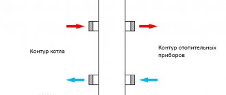
A hydraulic arrow is a device that is used to equalize pressure and temperature in a heating system. In the simplest case, a heating boiler circuit approaches it on one side, and a radiator circuit on the other, thus performing the function of a distribution manifold.
For more complex systems, a hydraulic arrow is installed in the boiler room in front of the distribution manifold, performing the same function - equalizing pressure in the system.
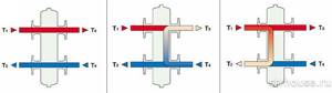
Structurally, the hydraulic arrow is made in the form of a vertical pipe, at the ends of which elliptical plugs are installed. If the coolant leaving the boiler has a temperature, and therefore a pressure, higher than necessary, then when it enters the hydraulic arrow, part of it goes into the heating circuit, and part of it is mixed with the cooled coolant from the return. Thus, stabilization and self-regulation of temperature and pressure in the system occurs. Visually, various cases of fluid flow are shown in the diagram:
The hydraulic distributor allows you to:
- avoid sudden temperature fluctuations that reduce the service life of the system;
- maintain the volume of water in the boiler heat exchanger at a constant level;
- maintain thermal equilibrium by separating the hydraulic circuit of the heat generator from the general system main.
The most complete optimization of the operation of a system with an installed hydraulic arrow is achieved through the use of a separate circulation pump for each circuit.
Heating comb
The distribution manifold for heating, unlike the boiler manifold, has much more modest dimensions, however, it performs similar functions. With the help of such a comb, the coolant coming from the boiler room is distributed either to consumers on the floor, or to various groups of consumers (underfloor heating collector, heating radiator collector).
The principle of operation is also somewhat different. If in the boiler manifold assembly the cooled coolant is completely replaced with heated liquid, then in the distribution comb they are also mixed and fed back into the system.
The functions of the hydraulic arrow in the combs are usually assigned to an additional circulation pump. With its help, the local heat-carrying fluid moves in a circle, entraining an additional portion of the heated coolant due to the different temperatures of the flows. At the same time, chilled water or antifreeze enters the main line. In accordance with this operating principle, a dosed amount of coolant is distributed into one or another heating circuit.
The distribution comb of the heating system is usually installed when there are three or more thermal appliances in one room and when a heated floor is installed. It helps to optimize the functioning of the entire complex and reduce the energy consumption of the heat generator.
Both the collector unit in the mini-boiler room and the distribution comb at first glance perform overlapping functions, but it is their joint use that makes the operation of the entire heating complex highly efficient.
Design of different types of combs
The most affordable would be a distribution comb with manual shut-off valves made in China or Turkey. Metal-plastic pipes are put on the collet connectors located on it.
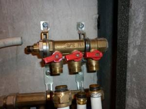
A budget distribution comb with valves has one significant drawback - water can drip from under the handle. Leakage occurs due to wear of rubber seals
Threads at the ends are needed for connecting shut-off valves and central hot water supply/discharge. In general, such a comb will cope with its function, but its flawless service life will not be very long.
If disassembling the valves and replacing worn seals does not lead to initial tightness, you will have to buy a new manifold.
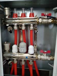
A more complex design would be a comb with plugs on the return manifold (and on the direct one too). Instead of them, flow meters and thermal heads can be installed in the future. The direct and reverse combs in such models are already connected by a bracket for mounting on the wall.
The presence of plugs makes it possible, if necessary, to improve the heating distribution manifold. To avoid problems with the installation of thermostats and other components in the future, it is necessary to provide convenient access to the comb at the stage of its installation
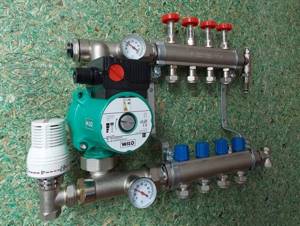
And finally, a complex and expensive, but the most effective distribution comb with factory-installed flow meters and thermal heads.
Flow meters regulate the uniform delivery of coolant to its destination, and thermal heads can adjust the temperature for each outlet separately, just like for a heating radiator. The types of thermal heads, their operating principles and installation features are discussed in more detail in our other article.
Flow meter caps allow you to visually monitor coolant flow through the circuits. Thermal heads regulate the flow of coolant into each of them
Even during the design process, it is necessary to make a choice between different types of combs, but in any case, the collector system is a preferable choice compared to conventional wiring based on such criteria as ease of use and durability.
Is it possible to make a heating collector with your own hands?
Sometimes it happens that the autonomous heating in your own home does not work very efficiently. It seems that the boiler power was selected correctly, the piping was done correctly, and all installation work was carried out at a professional level, but the temperature in the house is not what you would like. What to do in this case? There is only one way out - install a distribution manifold. By the way, there is no need to buy it ready-made, the design of the collector is not very complicated, so making it yourself is not the biggest problem. So, in this article we will answer one question: how to make a distribution manifold with your own hands?
Setting up a comb for heated floors
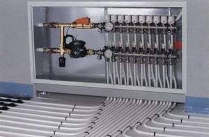
Factory products undergo bench testing, as evidenced by accompanying documents containing complete information about all hydrotests performed under special conditions. The use of such compact devices with a guarantee of tightness of welded and threaded connections is the best option in any in-house heating systems. Such units are characterized by an ergonomic arrangement of controls, and installation inside special mounting cabinets does not interfere with access to control valves.
After installation, the collector is configured with the servo drive and thermal head removed
The coolant from the supply pipe and the return pipe is mixed inside each outlet or directly in front of the collector, but it is advisable to entrust the calculation of the optimal circuit to specialists.
Regulating the temperature of the floor surface involves performing several sequential actions:
- Set the bypass valve to max, moving it to the 0.6 bar position. Triggering this node during the setup process causes an erroneous result.
- Calculate the balancing valve, using for this purpose the temperature indicators at the return, supply line and outlet of the heating device, under the conditions of a standard coefficient of 0.9 and according to the throughput formula: K = 0.9 × [(tk – to/tp – to) - 1]).
- Set up pumping equipment by calculating the boiling water flow rate and pressure loss on the circuits. It is allowed to set the minimum feed with a gradual addition of speed.
- Balance the branches by fully opening the control units and smoothly closing them to the required position.
At the final stage of setting up the comb for the “warm floor” system, the flow rate of the mixing unit is linked with other heating devices.
It should be noted that installing a flow meter will greatly facilitate obtaining accuracy when setting up all components. It is recommended to set the processing parameters of the bypass valve device approximately ten percent lower than the established maximum pressure values of the pumping equipment.
Both distributor and regulator
At its core, a distribution comb is a centralized unit that allows the coolant to be distributed to its destination points. In a heating system, it performs no less important function than a circulation pump or the same boiler. It distributes heated water through the mains and regulates the temperature.
This diagram shows the general operating principle of a collector block consisting of two combs: through one, coolant is supplied to the system, and through the second it is returned
This unit can be called a temporary coolant storage tank. It can be compared to a barrel filled with water, from which the liquid flows not through one hole, but through several. In this case, the pressure of water flowing out of all holes is the same. This ability to simultaneously ensure uniform distribution of heated liquid is the basic principle of operation of the device.
Externally, the collector looks like an assembly of two combs, most often made of stainless steel or ferrous metal. The terminals available in it are intended for connecting heating devices to it. The number of such outputs must correspond to the number of heating devices served. If the number of these devices increases, the unit can be expanded, so the device can be considered dimensionless.
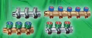
In addition to the leads, each comb is equipped with locking mechanisms. These can be two types of taps installed at the outlet:
- Cutting off. Such taps make it possible to completely stop the supply of coolant from the general system to its individual circuits.
- Regulatory. With the help of these taps, the volume of water supplied to the circuits can be reduced or increased.
The manifold includes valves for draining water and releasing air. It is also most convenient to place measuring equipment in the form of heat control meters here. In this case, everything that is necessary for the effective operation of this node will be in one place.
Why are there two combs in the manifold block? One serves to supply coolant to the circuits, and the second is responsible for collecting already cooled water (return) from the same circuits. All elements necessary for effective operation must be on each of the combs.
Criterias of choice
The number of collector outlets must correspond to the number of heating circuits.
The element model must be selected at the design stage. The number of outputs for the collector must correspond to the number of circuits. Due to the length of the routes and the pressure within the network, pumps are not used to force the flow of liquid. In private buildings where more than 100 meters are laid, additional draft must be created for pipes within the system. When installing heated floors, pressure drops also often occur.
A properly selected comb should balance performance characteristics. When choosing, they first look at the pressure indicators, as well as the temperature. Such an element can be of a simple or complex type; the second option is suitable for those who need a comb with auxiliary options. Innovative elements help you adjust and control temperature and other indicators.
Options with temperature sensors help determine in which rooms heat exchange occurs faster, where water provides less energy. Due to proper adjustment, liquid will not get where it is not needed.
When choosing, always take into account the material from which the comb is made. It can be cast iron, steel, brass or plastic. The ideal option would be cast elements that eliminate any leaks.
Features of collectors from various manufacturers
Rehau combs are excellent devices for balancing the system.
At the same time, they are resistant to leaching of alloy components and can be used for floor heating circuits in quantities from 2 to 12 pieces. The most modern models are equipped with flow meters, quick-acting taps on the supply pipe, and control valves on the return pipe. (See also: How to make heated floors at home with your own hands) The manifold cabinet for this device can be made in three modifications. One of the options is designed for hidden installation of a cabinet under a layer of plaster. The cabinet, intended for outdoor installation, is made of galvanized steel and has many modifications that differ in size.
Collectors produced by the Italian company FAR are widely used. This heating comb is used in many countries around the world due to its properties that meet most world standards. FAR manifolds are used for one-pipe and two-pipe heating systems, various types of materials from which devices and pipes are made. The product range of this company is surprisingly wide and varied: modular and non-regulating regulating manifolds, fittings for them and other components.
Use of materials is permitted only if there is an indexed link to the page with the material. For any questions please contact
Group: Forum participants
Messages: 200
Registration: 24.1.2007
User No: 5676
You can choose any temperature schedule - 15, 20 and 25 degrees C. Naturally, with an increase in delta T, the flow rate decreases, the diameters of the pipelines decrease, but the thermal pressure “delta Tm” also decreases - accordingly, this will lead to an increase in the total area of the heating devices. We need to count the costs. And the choice of pipeline diameters is regulated by the “noise limit” or the maximum speed of the carrier for each diameter.
Regarding the speed of movement of the carrier in the comb, if we recall the old Soviet systems, the concept of a comb and a collector was used extremely rarely; even in ITP, as the flow rate decreased, the diameter of the pipelines decreased.
Post edited by annuka
— 21.10.2007, 6:50
Today you can find innovative developments of heating systems, but water heating seems to always be in the lead. After all, such a system is effective and practical, most people are very happy with it. But every hydronic heating system can become less efficient over time. And then many begin to become interested in ways to modernize it.
These methods include a distribution heating manifold, which successfully replaces one- and two-pipe heating. Such a system can increase efficiency, ease of use and suitability for repairs. A mixing unit for heating is also used as an improvement to the underfloor heating system.
Heating distribution manifold
Features of narrow washing machines
Those who choose narrow washing machines are guided by the goal of saving living space, which is already small. And if this is a front-loading machine, then the lid also serves as a shelf, and its advantage is that it can be built into the kitchen work surface or under the bathroom sink. But narrow units with a vertical loading type allow you to add a forgotten item during the washing process.
Since the drum is not as large in diameter as in a standard machine, this affects the number of revolutions and, accordingly, the laundry may not be practically dry at the end of the process. Let's highlight machines of two washing classes and discuss them.
Class A
Good loading parameters for a narrow machine: 4.5 kilograms.
There is a choice of spin speed, delayed start, starching, the presence of a 3D-AquaSpar system and a FuzzyLogic control system.
No child protection. Lighting indicators indicate the washing progress.
Class B
Are there washing machines 55 cm wide? Yes, and one of these copies is DAEWOO DWD-CV701PC (height - 60, width - 55, depth - 28.7). Has a maximum load of 3 kilograms. The optimal choice for young mothers: it is almost silent and makes it possible to wash baby clothes at a temperature of 80 degrees. Energy consumption class - A. A washing machine with a height of 60 centimeters under the sink makes it possible to save space. It has an innovative design that will please the eye. The menu includes a shortened wash cycle.