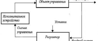
Elevator unit of the heating system: dimensions
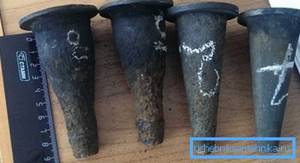
There are several categories of these devices; as a rule, they are designated by numbers. The category depends on the diameter of the elevator neck, its dimensions and the diameter of the nozzle.
| Number | Coolant flow | Neck diameter | Weight | Dimensions | |||||
| L | l1 | l2 | h | Flange 1 | Flange 2 | ||||
| 0.1-0.4 t/hour | 10mm | 6.4kg | 256mm | 85mm | 81mm | 140mm | 25mm | 32mm | |
| 1 | 0.5-1 t/hour | 15mm | 8.1kg | 425mm | 110mm | 90mm | 110mm | 40mm | 50mm |
| 2 | 1-2 t/hour | 20mm | 8.1kg | 425mm | 100mm | 90mm | 110mm | 40mm | 50mm |
| 3 | 1-3 t/hour | 25mm | 12.5kg | 625mm | 145mm | 135mm | 155mm | 50mm | 80mm |
| 4 | 3-5 t/hour | 30mm | 12.5kg | 625mm | 135mm | 135mm | 155mm | 50mm | 80mm |
| 5 | 5-10 t/hour | 35mm | 13kg | 625mm | 125mm | 135mm | 155mm | 50mm | 80mm |
| 6 | 10-15 t/hour | 47mm | 18kg | 720mm | 175mm | 180mm | 175mm | 80mm | 100mm |
| 7 | 15-25 t/hour | 59mm | 18.5kg | 720mm | 155mm | 180mm | 175mm | 80mm | 100mm |
Other options for thermal units
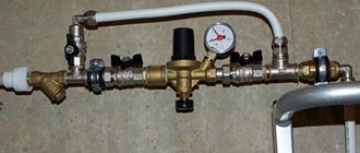
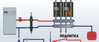
Improved mixing unit
Based on the basic principle of operation of the elevator unit of the heating system, alternative methods have been developed to maintain the desired temperature level in the pipes for users. Their difference from the traditional scheme lies in the presence of a complex electronic control system.
The first thing the developers of this unit paid attention to was the optimal flow of hot water. Therefore, a thermal energy meter must be installed at the inlet pipe
It makes it possible not only to see the volume of coolant entering the home system, but can also automatically calculate its cost and transmit the data to the management company.
The installed pumps allow you to control the speed of passage of the coolant through the pipes. This is necessary to reduce the error when mixing fluid flows in the nozzle. To do this, temperature sensors are mounted on the inlet and return pipes. If the water heating level is less than the set one, the return pump stops working. To increase the volume of hot coolant, the corresponding pumping equipment is activated.
- Dependency on power supply. The emergency source of electricity can only work for a short time. To protect against voltage surges, it is necessary to install a condensing rectifier;
- As the complexity of a system increases, the likelihood of system failure increases. It is enough for one of the sensors to fail - the optimal mixing parameters will change.
Despite these factors, the popularity of new systems is associated with their ease of use and significant savings on heating costs. This is why improved elevator units for central heating systems will be in demand.
As for the initial costs for the purchase of equipment and installation, these investments are returned in the form of savings on heating costs within 3-5 years. But provided that the design and installation are carried out by professional and honest companies.
An example of integrating an elevator heating unit in conjunction with a heat meter:
Installation features and testing
Installation of the elevator unit
It is worth immediately noting that installation and testing of the operation of the elevator unit and heating system is the prerogative of representatives of the service company. Residents of the house are strictly prohibited from doing this. However, knowledge of the layout of the elevator units of the central heating system is recommended.
When designing and installing, the characteristics of the incoming coolant are taken into account
The branching of the network in the house, the number of heating devices and the operating temperature are also taken into account. Any automatic elevator unit for heating consists of two parts
- Adjusting the intensity of the flow of incoming hot water, as well as measuring its technical indicators - temperature and pressure;
- Directly the mixing unit itself.
The main characteristic is the mixing coefficient. This is the ratio of the volumes of hot and cold water. This parameter is the result of precise calculations. It cannot be a constant, since it depends on external factors. The installation must be carried out strictly according to the diagram of the elevator unit of the heating system. After this, fine tuning is done. To reduce errors, a maximum load is recommended. This way the water temperature in the return pipe will be minimal. This is a prerequisite for precise control of the automatic valve.
After a certain period of time, scheduled checks of the operation of the elevator unit and the heating system as a whole are necessary. The exact procedure depends on the specific scheme. However, you can draw up a general plan that includes the following mandatory procedures:
- Checking the integrity of pipes, shut-off valves and devices, as well as compliance of their parameters with passport data;
- Adjustment of temperature and pressure sensors;
- Determination of pressure loss during coolant passage through the nozzle;
- Calculation of the displacement coefficient. Even for the most accurate heating scheme for an elevator unit, equipment and pipelines wear out over time. This amendment must be taken into account when setting up.
After this work has been completed, the automatic central heating elevator unit must be sealed to prevent tampering.
You cannot use homemade schemes of elevator units for central heating systems. They often do not take into account the most important characteristics, which can not only reduce operational efficiency, but also cause an emergency.
Possible problems and malfunctions
Despite the durability of the devices, sometimes the elevator heating unit malfunctions. Hot water and high pressure quickly find weak points and cause breakdowns.
This inevitably happens when individual components are assembled of poor quality, the calculation of the nozzle diameter is incorrect, and also due to the formation of blockages.
Noise
The heating elevator may create noise when operating. If this is observed, it means that cracks or scuffs have formed in the outlet part of the nozzle during operation.
The reason for the appearance of irregularities lies in the distortions of the nozzle caused by the supply of coolant under high pressure. This happens if the excess pressure is not throttled by the flow regulator.
Temperature mismatch
The quality operation of the elevator can also be questioned when the inlet and outlet temperatures differ too much from the temperature curve. Most likely, the reason for this is the oversized nozzle diameter.
Incorrect water flow
A faulty throttle will result in a change in water flow compared to the design value.
Such a violation can be easily determined by changes in temperature in the incoming and return piping systems. The problem is solved by repairing the flow regulator (throttle).
Faulty structural elements
If the connection diagram of the heating system to the external heating main has an independent form, then the cause of poor-quality operation of the elevator unit can be caused by faulty pumps, water heating units, shut-off and safety valves, all kinds of leaks in pipelines and equipment, and malfunction of regulators.
The main reasons that negatively affect the design and principle of operation of pumps include the destruction of elastic couplings in the connections of the pump and electric motor shafts, wear of ball bearings and destruction of seats for them, the formation of fistulas and cracks in the housing, aging of oil seals. Most of the listed faults can be eliminated by repair.
Unsatisfactory operation of water heaters occurs when the tightness of the pipes is broken, they are destroyed or the tube bundle sticks together. The solution to the problem is to replace the pipes.
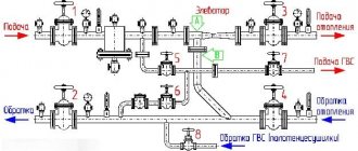
How does an elevator unit work?
Before understanding the structure of the elevator unit, we note that this mechanism is intended to connect end-users of heat to heating networks. By design, the thermal elevator unit is a kind of pump that is included in the heating system along with shut-off elements and pressure meters.
The elevator heating unit performs several functions. First of all, it redistributes the pressure inside the heating system so that water is supplied to the end consumers in the radiators at the specified temperature. When passing through pipelines from the boiler room to apartments, the amount of coolant in the circuit almost doubles. This is only possible if there is a supply of water in a separate sealed container.
As a rule, coolant is supplied from the boiler room, the temperature of which reaches 105-150 ℃. Such high rates are unacceptable for domestic purposes from a safety point of view. According to regulatory documents, the maximum water temperature in the circuit cannot exceed 95 ℃.
It is noteworthy that SanPin currently sets the coolant temperature standard within 60 ℃. However, in order to save resources, a proposal to reduce this standard to 50 ℃ is being actively discussed. According to an expert opinion, the difference will not be noticeable to the consumer, and in order to disinfect the coolant, it will need to be heated to 70 ℃ every day. However, these changes to SanPin have not yet been adopted, since there is no clear opinion about the rationality and effectiveness of such a decision.
The diagram of the elevator heating unit allows you to bring the temperature of the coolant in the system to standard values.
This node allows you to avoid the following consequences:
Batteries that are too hot can cause skin burns if handled carelessly; not all heating pipes are designed for prolonged exposure to high temperatures under pressure - such extreme conditions can lead to premature failure; if the wiring is made of metal-plastic or polypropylene pipes, it is not designed for the circulation of hot coolant.
Switchgears
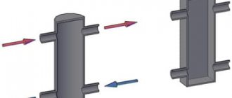
The elevator unit with all its piping can be thought of as a pressure circulation pump, which supplies coolant to the heating system under a certain pressure.
If the facility has several floors and consumers, then the most correct solution is to distribute the total coolant flow to each consumer.
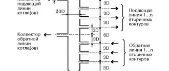
To solve such problems, a comb is designed for the heating system, which has another name - a collector. This device can be represented as a container. The coolant flows into the container from the elevator outlet, which then flows out through several outlets, with the same pressure.
Consequently, the distribution comb of the heating system allows the shutdown, adjustment, and repair of individual consumers of the facility without stopping the operation of the heating circuit. The presence of a collector eliminates the mutual influence of the heating system branches. In this case, the pressure in corresponds to the pressure at the elevator outlet.
Scheme development
At the initial stage, heating engineers work on the development of a heating scheme, carry out a series of calculations and achieve the same efficiency indicators of the heating system on all floors of the building. They draw up an axonometric diagram of the heating system, which is subsequently used by installers. Calculations carried out correctly by specialists guarantee that the designed heating system will be characterized by optimal coolant pressure, which will not lead to water hammer and interruptions in operation.
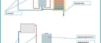
Inclusion of an elevator unit in the heating scheme
The central heating scheme for an apartment building, prepared by heating engineers, assumes that the radiators located in the apartment will receive coolant at an acceptable temperature. However, at the exit from the boiler room, the water temperature can exceed 100 degrees. To achieve cooling of the coolant by mixing cold water, the return and supply lines are connected by an elevator unit.
A reasonable heating elevator design allows the unit to perform a number of functions. The main function of the unit is direct participation in the heat exchange process, since the hot coolant entering it is dosed and mixed with the injected coolant from the return. As a result, the unit allows you to achieve optimal results in matters of mixing hot coolant from the boiler room and cooled water from the return. After this, the prepared coolant at the optimal temperature is supplied to the apartments.
Design features of the circuit
An effective heating system in an apartment building, the design of which requires competent calculations, also implies the use of many other structural elements. Immediately after the elevator unit, special valves are integrated into the heating system to regulate the supply of coolant. They help control the heating process of the entire house and individual entrances, but only employees of service utility companies have access to these devices.
In the heating circuit, in addition to thermal valves, more sensitive devices are used to regulate and adjust the heating.
We are talking about devices that increase the performance of the heating system and allow for maximum automation of the home heating process. These are devices such as collectors, thermostats, automation, heat meters, etc.
Elevator with adjustable nozzle.
Now we just have to figure out how to more easily regulate the temperature at the elevator outlet
, and is it possible to save heat using an elevator?
It is possible to save heat using a water jet elevator, for example, by lowering the room temperature at night
, or during the day when most of us are at work.
Although this issue is also controversial, we lowered the temperature, the building cooled down, therefore, in order to reheat it, the heat consumption must be increased against the norm. There is only one benefit: at a cool temperature of 18-19 degrees, we sleep better
, our body feels more comfortable.
Wednesday is assumed to last. It is complete - if it is equipped with all the elements that allow it to function as intended. It is suitable for use - if it is technically and legally legal in the form of statements, approvals and permissions for use.
The tax authorities assume that installations, systems and equipment installed in buildings can be considered complete and fit for use if. Enable all structural components to function as intended; This does not mean, however, that they are capable of self-employment.
For heat saving purposes, a special water jet elevator with an adjustable nozzle
. Structurally, its design and, most importantly, the depth of quality adjustment can be different. Typically, the mixing coefficient of a water-jet elevator with an adjustable nozzle varies in the range from 2 to 5. As practice has shown, such adjustment limits are quite sufficient for all occasions. Danfoss offers a control range of up to 1 in 1000. Why this is used in a heating system is completely unclear to us. But the price ratio in favor of a water jet elevator with an adjustable nozzle relative to Danfoss regulators is approximately 1 to 3. True, we must pay tribute to Danfos, their products are more reliable, although not all of them; some varieties of inexpensive three-way valves do not work well on our water. Recommendation – you need to save wisely!
Basic elements of the elevator
They are not permanently connected to the building, i.e. they can be switched off without damaging the building structure or installations, systems and devices. To determine whether a particular item can be considered permanent or not, you must use the classification of fixed assets.
Advantages of water jet elevators
Of course, this does not mean that every installation, system or device installed in a building can be a self-contained environment. For this to happen, the component in question. He must be classified as a permanent agent in the CST and must not be presented at the same time as the clarification in the building equipment.
Fundamentally, all regulating elevators are designed in the same way. Their device is clearly visible in the figure.
. , you can see an animated image of the operation of the VARS control mechanism of a water-jet elevator.
And finally, a short comment - the use of water-jet elevators with an adjustable nozzle
especially
effective in public and industrial buildings
where it allows you to save up to 20-25% of heating costs by lowering the temperature in heated rooms at night and, especially, on weekends.
The opinion of the statistical office will be useful
It cannot be permanently connected to the building, i.e. it can be switched off without damaging the building, installation, system or equipment. Classification of durable means is a systematic collection of objects of durable properties. For accounting purposes, establish depreciation rates and statistical tests. The allocation of a given measure for the corresponding classification of fixed assets is determined by its purpose, design and equipment.
The authority authorized to do this is the statistical office. Therefore, the reader should contact the statistical office for assistance in classifying the asset. The statistical conclusion of the classification bureau will be important evidence before the tax authorities.
The elevator unit of the heating system is used to connect the house to an external heating network (heat supply source) if it is necessary to reduce the temperature of the coolant by mixing water from the return pipeline.
How the device works
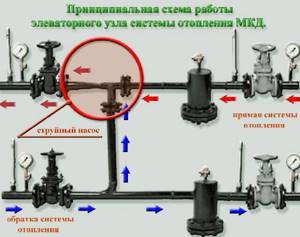
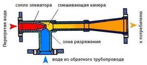
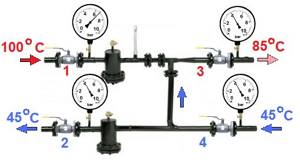
The device is a fairly large container, as it includes a mixing chamber. Dirt traps and magnetic mesh filters are installed in front of the chamber: the quality of tap water in our cities is never high. The photo shows a diagram of a heating elevator.
Purified water enters the mixing chamber at high speed. Due to the vacuum, the return water is sucked in spontaneously and mixed with the superheated water. The coolant is supplied to the network through a nozzle. It is clear that the size of the hole in the nozzle determines the water temperature and pressure. Devices with an adjustable nozzle and a constant one are produced; their general operating principle is the same.
A certain ratio must be maintained between the pressure inside the supply pipe and the resistance of the heating elevator: 7 to 1. With other indicators, the operation of the device will be ineffective. The pressure in the supply pipe and return pipe is also important - it should be almost the same.
Heating elevator with adjustable nozzle
The operating principle of the device is exactly the same: mixing the coolant and distributing it throughout the network due to the resulting pressure difference. However, an adjustable nozzle allows you to set different temperatures for certain times of the day, for example, and thereby save heat.
- The diameter itself does not change, but an additional mechanism is installed in the adjustable nozzle. Depending on the value indicated on the sensor, the throttle needle moves along the nozzle, reducing or increasing its working cross-section, which will change the size of the hole. The mechanism requires power to operate. The photo shows a heating elevator with an adjustable nozzle.
Public institutions and industrial facilities receive the greatest benefit from the device, since for most of them heating rooms at night is not necessary - supporting the minimum mode is quite enough. The ability to set a lower temperature at night significantly reduces heat energy consumption. Savings can reach 20–25%.
In residential apartment buildings, a device with an adjustable nozzle is used much less frequently, and in vain: at night, a temperature of +17–18 C instead of 22–24 C is more comfortable. Reducing the temperature also allows you to reduce heating costs.
Based on the book by M.M. Aprartseva “Adjustment of water systems of centralized heating supply” Moscow Energoatomizdat 1983
Currently, most heating systems are connected using an elevator connection scheme. At the same time, as practice has shown, many do not quite understand the operating principles of elevator units. As a result, the operating efficiency of heating systems is not always acceptable. At normal coolant temperatures in rooms and apartments, the temperature is either too low or too high. This effect can be observed not only when elevators are configured incorrectly, but most problems arise precisely for this reason. Therefore, the greatest attention should be paid to the calculation and adjustment of the elevator unit. The estimated diameter of the elevator neck, mm, is determined by the formula:
Where: N is the available pressure, m. In order to avoid vibration and noise, which usually arise when the elevator operates under a pressure 2-3 times higher than the required one, it is recommended to dampen part of this pressure with a throttle diaphragm installed in front of the mounting pipe to the elevator. A more effective way is to install a flow regulator in front of the elevator, which will allow you to configure and operate the elevator unit as efficiently as possible. When choosing an elevator number based on the estimated diameter of its neck, you should choose a standard elevator with the nearest smaller neck diameter, since an overestimated diameter leads to a sharp decrease in the efficiency of the elevator. The nozzle diameter should be determined to the nearest tenth of a mm, rounded down. The diameter of the nozzle opening must be at least 3 mm to avoid clogging. When installing one elevator on a group of small buildings, its number is determined based on the maximum pressure losses in the distribution network after the elevator and in the heating system for the most unfavorably located consumer, which should be taken with K = 1.1. In this case, a throttle diaphragm should be installed in front of the heating system of each building, designed to dampen all excess pressure at the calculated flow rate of mixed water. After calculating and installing the elevator, it is necessary to fine-tune and adjust it. Adjustment should only be carried out after all previously developed adjustment measures have been completed. Before adjusting the heat supply system, the operation of the automatic devices provided for in the development of measures to maintain the specified hydraulic mode and trouble-free operation of the heat source, network, pumping stations and heating points must be ensured. Adjustment of the centralized heat supply system begins with recording the actual water pressures in the heating networks during operation of the network pumps provided for in the design mode, and maintaining a given pressure in the return manifold of the heat source. If, when comparing the actual piezometric graph with the given one, significantly increased pressure losses are found in sections, it is necessary to establish their cause (functioning jumpers, not fully open valves, discrepancy between the pipeline diameter and the one accepted in the hydraulic calculation, blockages, etc.) and take measures to eliminate them . In some cases, if it is impossible to eliminate the causes of higher than calculated pressure losses, for example, with underestimated pipeline diameters, the hydraulic regime can be adjusted by changing the pressure of the network pumps so that the available pressures at the thermal inputs of consumers correspond to the calculated ones. Adjustment of heat supply systems with a hot water supply load, for which the hydraulic and thermal modes were calculated taking into account the corresponding regulators on the thermal inputs, is carried out if these regulators are working properly. Adjustment of heat consumption systems and individual heat-consuming devices is based on checking the compliance of actual water consumption with calculated ones. In this case, the calculated flow rate refers to the water flow rate in a heat consumption system or in a heat-consuming device that provides a given temperature schedule. The calculated flow rate corresponds to what is necessary to create the design temperature inside the premises, provided that the established heating surface area corresponds to the required one. The degree to which the actual water consumption corresponds to the calculated one is determined by the temperature difference of the water in the system or in a separate heat-consuming device. In this case, the actual water temperature in the network should not deviate from the schedule by more than 2 ° C. An underestimated temperature difference indicates an overestimated water flow and, accordingly, an overestimated diameter of the throttle diaphragm or nozzle opening. An increased temperature difference indicates an underestimated water flow and, accordingly, an underestimated diameter of the throttle diaphragm or nozzle opening. The correspondence of the actual consumption of network water to the calculated one in the absence of metering devices (flow meters) with sufficient accuracy for practice is determined: for heat consumption systems connected to networks through elevators or mixing pumps, according to the formula
(6)
Where: y = Gф/Gр - the ratio of the actual flow of network water entering the heating system to the calculated one; t » 1, t » 3 and t » 2 - water temperatures measured at the thermal input, respectively, in the supply pipeline, mixed and return, gr.C; t 1 , t 2 and t 3 - water temperatures, respectively, in the supply pipeline, mixed and reverse according to the temperature schedule at the actual outside air temperature, deg. C; t » in and t in - actual and calculated indoor air temperatures; For heat consumption systems of residential and administrative buildings connected to the heating network without mixing devices, as well as for heating and recirculation heater installations according to the formula:
Where Tn is the actual outside air temperature. The adjusted diameter of the elevator nozzle, as well as the throttle diaphragm installed in front of the system, the calculated pressure drop in which is small compared to the available pressure at the input of this system (no more than 5-10%) is determined by the formula:
if it is impossible to determine the actual pressure losses in the system, according to their calculated value hр, m, according to the formula:
(11)
where H is the available pressure in front of the heat consumption system or heat receiver. The hр value is taken according to design data or hydraulic calculation data. Temperature measurements at the heating point are made at a stable water temperature in the supply pipeline, which does not differ from the temperature specified according to the temperature schedule by more than 2 degrees C. Replacement of elevator nozzles and throttle diaphragms is carried out at values of 0.9>y>1.15, if the installed heating surface area corresponds to that necessary to maintain the calculated internal temperature in the premises. If the heating surface area of the actually installed heating devices does not correspond to the required one, replacement of elevator nozzles and throttle diaphragms should be carried out after analyzing the internal temperature in the premises. Thus, with excess areas of heating surfaces, the heat consumption system must operate with a relative water flow rate of If, after replacing the elevator nozzle or throttle diaphragm, checking the internal temperature of the heated premises shows that it differs from the calculated one by more than 2 degrees C, it is necessary to adjust the diameter of the nozzle hole a second time or diaphragm according to formulas (9)-(11). The relative water flow in this case is calculated using the formula
https://www.rosdon.h1.ru/elevator.html
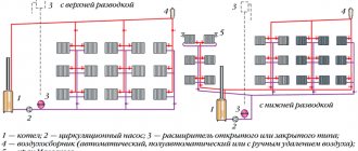
Multi-storey buildings, high-rise buildings, administrative buildings and many different consumers provide heat from combined heat and power plants or powerful boiler houses. Even a relatively simple autonomous system in a private home is sometimes difficult to adjust, especially if errors were made during the design or installation. But the heating system of a large boiler house or thermal power plant is incomparably more complex. There are many branches leaving the main pipe, and each consumer has different pressure in the heating pipes and the amount of heat consumed.
Pipe lengths vary and the system must be designed so that the furthest consumer receives sufficient heat. It becomes clear why there is coolant pressure in the heating system. Pressure moves water along the heating circuit, i.e. created by the central heating line, it plays the role of a circulation pump. The heating system must not allow imbalance when the heat consumption of any consumer changes.
In addition, the efficiency of heat supply should not be affected by the branching of the system. In order for a complex centralized heating system to operate stably, it is necessary to install either an elevator unit or an automated heating system control unit at each facility to eliminate mutual influence between them.
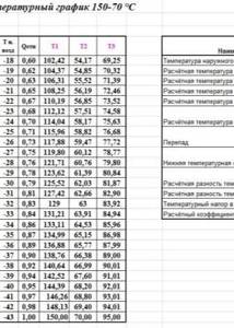
Heating engineers recommend using one of three temperature modes for boiler operation. These modes were initially calculated theoretically and underwent many years of practical application. They ensure heat transfer with minimal losses over long distances with maximum efficiency.
Thermal conditions of a boiler room can be defined as the ratio of the supply temperature to the return temperature:
In real conditions, the mode is selected for each specific region based on the winter air temperature. It should be noted that high temperatures, especially 150 and 130 degrees, cannot be used for heating premises in order to avoid burns and serious consequences in case of depressurization.
The temperature of the water exceeds the boiling point and it does not boil in the pipelines due to the high pressure. This means that it is necessary to reduce the temperature and pressure and ensure the necessary heat extraction for a particular building. This task is assigned to the elevator unit of the heating system - special heating equipment located in the heat distribution point.
Calculation
The operation of the elevator unit depends on the correctly selected dimensions and pressure difference between the discharge and return pipelines. To calculate the parameters of the elevator unit, heating engineers and programmers have created quite a lot of programs. They look like a regular screen form with a customized formula for calculations. After filling out all the rows of the table, the program calculates the parameters of the hot water supply scheme, the dimensions of the elevator and displays the results in the form of a diagram with plotted dimensions and in the form of a table with calculations. The option for displaying results is usually presented in the form of a table.
The calculation of the heating network and the choice of elevator is described in some detail in the Building Codes and Rules:
- SNiP 23-01-99 “Building climatology”, 2000;
- SNiP II-3-79 “Construction Heat Engineering”, 1998;
- SNiP 2.04.05-91 “Heating, ventilation and air conditioning”, 1987;
- Bogoslovsky V.N. “Internal sanitary installations”, 1990.
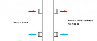
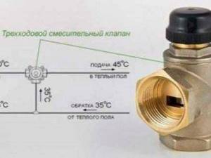
The mixing thermostat is an alternative to the standard elevator unit. It works in exactly the same way as an elevator - it mixes the hot water coming from the thermal power plant and the cooled water that returns from the radiators. Three channels are connected to the thermostat: one for hot water, the second for return, and the third for supplying the prepared mixture to the heating radiators. If the temperature of the water from the main pipeline is within acceptable limits, the cold flow is completely blocked. As soon as the temperature begins to rise, the valve gradually begins to open, a portion of cool water is added to the hot water, lowering the temperature of the mixture. The hotter the water, the larger the volume of cool water is added. A three-way mixing thermostat valve is necessary to control the proportion of cold and hot water in order to obtain the coolant at the optimal temperature. Advantages: small dimensions, no moving parts, easy temperature adjustment.
Elevator what is it
To understand and understand what this element is, it is best to go down to the basement of the building and see it with your own eyes. But if you have no desire to leave your home, then you can view the photo and video files in our gallery. In the basement, among the many gate valves, pipelines, pressure gauges and thermometers, you will definitely find this unit.
We suggest first understanding the principle of operation. Hot water is supplied to the building from the district boiler house, and cooled water is discharged.
This requires:
- Supply pipeline
– supplies hot coolant to the consumer; - Return pipeline
- performs the work of removing the cooled coolant and returning it to the district boiler room.
Several houses, and in some cases each one if the houses are large, are equipped with thermal chambers. They distribute coolant between houses, and also install shut-off valves that serve to cut off pipelines. Drainage devices can also be installed in the chambers, which are used to empty pipes, for example, for repair work. Further, the process depends on the temperature of the coolant.
In our country there are several main modes of operation of district boiler houses:
- Supply 150 and return 70 degrees Celsius;
- Respectively 130 and 70;
- 95 and 70.
The choice of mode depends on the latitude of residence. So, for example, for Moscow a 130/70 schedule will be sufficient, but for Irkutsk a 150/70 schedule will be needed. The names of these modes have the numbers of the maximum load of the pipelines. But depending on the air temperature outside the window, the boiler room can operate at temperatures of 70/54.
This is done to prevent overheating in the rooms and to make them comfortable to stay in. This adjustment is performed at the boiler room and is a representative of the central type of adjustment. An interesting fact is that in European countries a different type of regulation is performed - local. That is, adjustment takes place at the heat supply facility itself.
In this case, heating networks and boiler houses operate at maximum capacity. It is worth saying that the highest performance of boiler units is achieved precisely at maximum loads. comes to the consumer and is locally regulated by special mechanisms.
These mechanisms consist of:
- Outdoor and indoor temperature sensors;
- Servo drive;
- Actuator with valve.
Such systems are equipped with individual devices for metering thermal energy, thereby achieving great savings in monetary resources. Compared to elevators, such systems are less reliable and durable.
So, if the coolant has a temperature of no more than 95 degrees, then the main task is the high-quality physical distribution of heat throughout the system. To achieve these goals, manifolds and balancing valves are used.
But in the case when the temperature is above 95 degrees, it needs to be reduced a little. This is what elevators do in the heating system; they add chilled water from the return line to the supply pipeline.
Features and Specifications
As we have already figured out, the elevator of the heating system is responsible for cooling the superheated water to a given value. This prepared water then enters.
This element improves the quality of operation of the entire building system and, when properly installed and selected, performs two functions:
- Mixing;
- Circulation.
Advantages of the elevator heating system:
- Simplicity of design;
- High efficiency;
- No electrical connection required.
Flaws:
- We need accurate and high-quality calculation and selection of a heating elevator;
- There is no way to regulate the outlet temperature;
- It is necessary to maintain a pressure difference between supply and return of around 0.8-2 bar.
Nowadays, such elements have become widespread in heating networks. This is due to their advantages, such as resistance to changes in hydraulic and temperature conditions. In addition, they do not require constant human presence.
Design
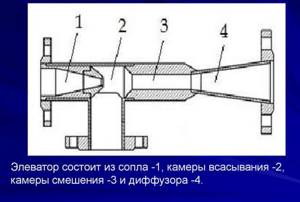
The elevator consists of:
- Vacuum chambers;
- Nozzles;
- Jet elevator.
Among heating engineers there is a concept called piping an elevator unit. It consists of installing the necessary shut-off valves, pressure gauges and thermometers. All this is assembled and is a unit.
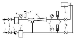
Example of implementation of scheme 1 ACU
Schematic diagram of an automated control unit with a sufficient available pressure drop at the inlet
(P1 - P2 > 6 m water column) for temperatures up to AUU t = 95-70 °C
The modern world has long been unable to cope without innovative technologies. There is not a single technology or system that does not use revolutionary solutions. The heating system was no exception. This is due to the fact that this is a fairly significant technology, which is designed to ensure a comfortable existence.
For obvious reasons, special attention is paid when designing a house. Since ancient times, houses were built from the stove, that is, first the stove was built, and then it was covered with walls and a ceiling
This was done for a reason; for this we need to say “thank you” to our climate.
Starting from the middle zone of our spacious country and ending with distant Sakhalin, rather uncomfortable temperatures reign for most of the year. The thermometer ranges from +30 to -50 degrees.
Due to the rather complex temperature resonance, the heating system is as important as the electrical supply. Previously, a competent stove maker who knew how to make a proper stove was valued at the level of a blacksmith. After all, you need to correctly calculate the size of the firebox, the diameter of the chimney, and besides, the stove had to be multifunctional:
- food was prepared in it;
- it heated the room;
- warmed up the water;
- served as a small sleeping place.
That is why the construction of the furnace was complex and time-consuming. It had to have sufficient draft to ensure that all combustion products did not enter the room. But with all this, she had to be economical.
Today, fundamentally little has changed. The main functions and requirements for the heating system remain the same:
- saving;
- maximum efficiency;
- multifunctionality;
- simplicity of design;
- quality and durability;
- minimal operating costs;
- safety.
Fire was the first source of heat for humans. And even now its relevance has not lost its significance. The most primitive way of heating was to make a fire, which provided protection from predators, low temperatures, and served as a source of light.
Further, over time, humanity began to tame the gift of Hermes. Ovens appeared, they were usually built from clay and stones. Later, with the advancement of technology, ceramic bricks began to be used. And it was then that the first ones appeared.
Steel furnaces appeared much later; they determined the formation of the Steel Age. The fuel for the stoves was coal, wood, and peat. With the gasification of cities, furnaces became available. And all this time, man sought to improve the heating system.
Common failures of the elevator unit
The main malfunctions of the heating system elevator can be caused by failure of the device itself due to clogging or an increase in the internal diameter of the nozzle. Also, the cause of the breakdown may be a clogged mud trap. breakdown of shut-off valves and failure of regulator settings.
The breakdown of the elevator unit of the heating system can be determined by the temperature difference before and after the device. If a strong difference is detected, it can be stated that the elevator is broken due to clogging or an increase in the diameter of the nozzle. But regardless of the breakdown, diagnostics are carried out by certified specialists. If the elevator unit is clogged, it is cleaned.
If the original diameter has increased due to corrosion, then the entire heating system will be completely unbalanced. In this case, the radiators in the rooms on the top floor will not receive thermal energy in full, and the radiators in the lower apartments will overheat greatly. To eliminate the problem, the nozzle is replaced with a new analogue with the required diameter.
Clogging of the mud traps in the elevator heating unit can be detected by changing the readings of pressure sensors located immediately before and after the device. To remove contaminants in the thermal system, they are discharged using a tap located in the lower part of the sump. If such actions do not give positive results, then the device is dismantled and mechanically cleaned.
Territories of responsibility
What is an elevator heating unit - we have at least figured it out.
And who is responsible for it?
- The section of the highway into houses up to the flanges of the inlet valves is the territory of responsibility of the heat transporting organization (heating networks).
- Everything after the entrance valves, and the valves themselves, are the responsibility of the housing organization.
But: selection of a heating elevator by number (standard size), calculation of retaining washers and nozzle diameter are carried out by heating networks. Housing workers only provide dismantling and installation.
What is it and what is it used for
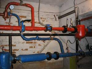
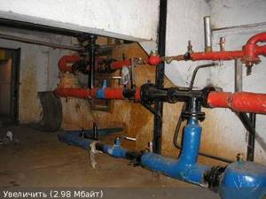
Working device in the basement
The easiest way to find out what an elevator unit is is to visit the basement of an ordinary multi-story building.
Among the many parts of the heating system, it will not be difficult to find this important component.
Let's look at a simple diagram. How does heat enter the house? There are two pipelines: supply and return. The first is to supply hot water to the house. With the help of the second, cold water from the system enters the boiler room.
The thermal chamber supplies hot water to the basement of the house
Please note that shut-off valves must be installed at the entrance
This can be a simple gate valve, or steel ball valves. The temperature of the coolant determines how it will continue to work. There are three main heat levels:
If the coolant temperature is not higher than 95° C, then all that remains is to distribute the heat throughout the entire heating system. This is where a manifold with balancing valves comes in handy.
However, everything becomes not so simple if the temperature of the coolant goes beyond the norm of 95 ° C. Such water cannot be put into the heating structure, so the heating must be reduced. This is precisely the important function of the elevator unit.
How to order and buy a water jet elevator 40s10bk?
In order to buy an elevator, you must send a request to the sales department using the coordinates on the CONTACTS . The request must indicate the elevator number and quantity, as well as the need for delivery. A price offer will be sent to you in response, indicating the current cost and availability of the goods in stock.
You can also send a request using a special form - SEND A REQUEST on the website.
Delivery is carried out by transport companies to all regions of the Russian Federation. It is possible to ship products to the countries of the Customs Union (Armenia, Belarus, Kazakhstan, Kyrgyzstan). Delivery costs are calculated and paid additionally.
Master Class. An example of installing a heating radiator with your own hands
Let's consider the algorithm of actions when connecting a battery to a heating system.
Step 1. First, prepare and assemble the heating radiator itself. Clean all threaded holes from factory grease, for which you can use a special cleaning agent and a brush.
Radiator preparation
Step 2. When finished, remove any remaining cleaning product with a paper towel.
It is important that the holes are as clean and dry as possible.
The hole is wiped dry
Step 3. Install adapters (in our example these are ½ and ¾ inches).
Adapter
Step 4. Install the “American” faucet onto the adapter that you installed in advance. To tighten, use a special key for “American women”. As a result, you will equip a pair of holes - inlet and outlet (in the example they are located diagonally).
The “American” is installed. The key for “American” is used. The key for “American” is used.
Step 5. Install plugs on any unnecessary holes that need to be closed.
Installing the plug
Step 6. Prepare the shanks (these are special thin tubes) and cut them. Remove the internal chamfer in the shanks
Then feel the internal parts - it is important that you do not feel any burrs there
The tube (shank) is being prepared. A device for removing the internal chamfer
Step 7. Place the nut, brass spacer and rubber band on the tube (in that order). Then expand the tube using a special device, inserting it inside until it stops. After expansion, the tube will no longer be able to jump out of its place under the influence of pressure during operation of the heating system.
Pipe expansion
Step 8. Move the elastic and other parts to the extended edge, attach the adapter.
Step 9. Mark the place where the radiator will be installed on the wall, in accordance with the requirements described above. To begin, determine the center of the window sill, measure down 10 cm - the battery mounts will be located exactly at this level.
Marking
Step 10. Draw a line for installing the holders parallel to the window sill at a distance of 10 cm. The holders themselves will be attached to dowels.
Drawing a line for installing holders
Step 11. Another fastener will be located 12 cm from the floor surface along the vertical center line.
Installing the Bottom Mount
Step 12. Place the battery on the mounts and level it.
Heating radiator installation
Step 13. Mark on the wall the places where the grooves will be located (in our example, the pipes will be laid inside the wall). Do this in all places where pipes will be connected to the radiator.
Marking for future wall grooves
Step 14. Perform grooves on the previously planned areas. Remove the battery to make it easier to carry out work.
Grooving
Step 15: Prepare the tubes. Make a mark where they will be cut, as shown in the picture below.
Preparing pipes for connecting the radiator
Step 16. Connect the battery and faucet to the soft line laid in the wall. Tighten all connections tightly. The input should be located at the top, and the output, accordingly, at the bottom.
Pipe connection
Video - How to install a heating radiator
If you choose a suitable scheme and familiarize yourself with all the nuances of the connection, then installing the radiator yourself will be quick and without any problems. You just need to act carefully and do everything efficiently. The quality of heating your home depends on how correctly you do everything!