Principle of operation
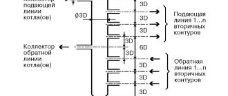
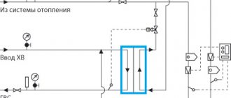
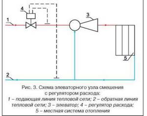
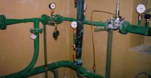
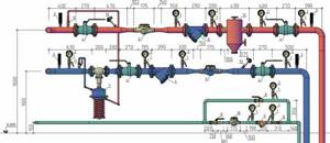
To understand how the node works, it is necessary to give an example. To do this, we will take a three-story house, since the elevator unit is used specifically in multi-story buildings. The main part of the equipment that belongs to this system is located in the basement. The diagram below will help us better understand the work. We see two pipelines:
- The server.
- Back.
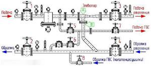
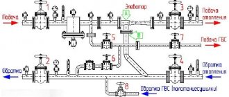
Diagram of a heating unit for a multi-storey building.
Now you need to find on the diagram the thermal chamber through which water is sent to the basement. You can also notice shut-off valves, which must be installed at the entrance. The choice of fittings depends on the type of system. For the standard design, valves are used. But if we are talking about a complex system in a multi-story building, then the experts recommend using steel ball valves.
When connecting a thermal elevator unit, you must adhere to the standards. First of all, this concerns temperature conditions in boiler rooms. During operation, the following indicators are allowed:
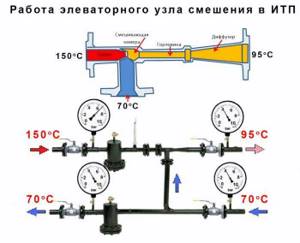
When the liquid temperature is in the range of 70-95°C, it begins to be evenly distributed throughout the system due to the operation of the collector. If the temperature exceeds 95°C, the elevator unit begins to work to lower it, since hot water can damage equipment in the house, as well as shut-off valves. This is why this type of construction is used in multi-storey buildings - it controls the temperature automatically.
Advantages of the elevator
Many consumers say that the heating elevator design is irrational, and it is much easier to supply users with coolant at a lower temperature. In fact, this approach involves increasing the diameter of the central heating pipeline to circulate cooler coolant, which implies additional costs.
That is, a high-quality heating unit design allows you to use part of the cooled water from the return flow with the supply volume of coolant. Despite the fact that some elevator sources are outdated hydraulic devices, in fact, they are the most efficient in operation . There are also more modern devices that have replaced elevator unit systems.
This includes the following types of devices:
- mixer equipped with a three-way membrane;
- plate heat exchanger.
Example of implementation of scheme 1 ACU
Schematic diagram of an automated control unit with a sufficient available pressure drop at the inlet
(P1 - P2 > 6 m water column) for temperatures up to AUU t = 95-70 °C
The modern world has long been unable to cope without innovative technologies. There is not a single technology or system that does not use revolutionary solutions. The heating system was no exception. This is due to the fact that this is a fairly significant technology, which is designed to ensure a comfortable existence.
For obvious reasons, special attention is paid when designing a house. Since ancient times, houses were built from the stove, that is, first the stove was built, and then it was covered with walls and a ceiling. This was done for a reason, for this we need to say “thank you” to our climate
This was done for a reason; for this we need to say “thank you” to our climate.
Starting from the middle zone of our spacious country and ending with distant Sakhalin, rather uncomfortable temperatures reign for most of the year. The thermometer ranges from +30 to -50 degrees.
Due to the rather complex temperature resonance, the heating system is as important as the electrical supply. Previously, a competent stove maker who knew how to make a proper stove was valued at the level of a blacksmith. After all, you need to correctly calculate the size of the firebox, the diameter of the chimney, and besides, the stove had to be multifunctional:
- food was prepared in it;
- it heated the room;
- warmed up the water;
- served as a small sleeping place.
That is why the construction of the furnace was complex and time-consuming. It had to have sufficient draft to ensure that all combustion products did not enter the room. But with all this, she had to be economical.
Today, fundamentally little has changed. The main functions and requirements for the heating system remain the same:
- saving;
- maximum efficiency;
- multifunctionality;
- simplicity of design;
- quality and durability;
- minimal operating costs;
- safety.
Fire was the first source of heat for humans. And even now its relevance has not lost its significance. The most primitive way of heating was to make a fire, which provided protection from predators, low temperatures, and served as a source of light.
Further, over time, humanity began to tame the gift of Hermes. Ovens appeared, they were usually built from clay and stones. Later, with the advancement of technology, ceramic bricks began to be used. And it was then that the first ones appeared.
Steel furnaces appeared much later; they determined the formation of the Steel Age. The fuel for the stoves was coal, wood, and peat. With the gasification of cities, furnaces became available. And all this time, man sought to improve the heating system.
Purpose and characteristics
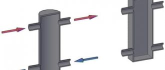
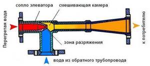
The heating elevator cools the superheated water to the design temperature, after which the prepared water enters the heating devices located in residential premises. Cooling of water occurs at the moment when hot water from the supply pipeline is mixed with cooled water from the return pipeline in the elevator.
Schematic diagram of the elevator unit
The heating elevator diagram clearly shows that this unit helps to increase the efficiency of the entire heating system of the building. It is assigned two functions at once - a mixer and a circulation pump. Such a unit is inexpensive and does not require electricity. But the elevator also has several disadvantages:
- The pressure difference between the direct and reverse supply pipelines should be 0.8-2 Bar.
- The output temperature cannot be adjusted.
- There must be an accurate calculation for each elevator component.
Elevators are widely used in municipal heating systems, since they are stable in operation when the thermal and hydraulic conditions in heating networks change. The heating elevator does not require constant monitoring; all regulation consists of choosing the correct nozzle diameter.
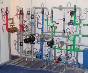
Elevator unit in the boiler room of an apartment building
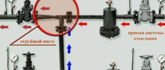
The heating elevator consists of three elements - a jet elevator, a nozzle and a vacuum chamber. There is also such a thing as elevator piping. The necessary shut-off valves, control thermometers and pressure gauges must be used here.
The selection of a heating elevator of this type is due to the fact that here the mixing coefficient varies from 2 to 5, in comparison with conventional elevators without nozzle regulation, this indicator remains unchanged. Thus, in the process of using elevators with an adjustable nozzle, heating costs can be slightly reduced.
Elevator structure
The design of this type of elevator includes a regulating actuator that ensures stable operation of the heating system at low flow rates of network water. The cone-shaped nozzle of the elevator system houses a regulating throttle needle and a guide device, which spins the water stream and plays the role of a throttle needle casing.
This mechanism has a gear shaft rotating either electrically or manually. It is designed to move the throttle needle in the longitudinal direction of the nozzle, changing its effective cross-section, after which the water flow is regulated. Thus, you can increase the consumption of network water from the calculated indicator by 10-20%, or reduce it almost until the nozzle is completely closed. Reducing the nozzle cross-section can lead to an increase in the flow rate of network water and the mixing coefficient. This way the water temperature decreases.
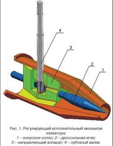
Actuator mechanism of the heating elevator unit
Installation features and testing
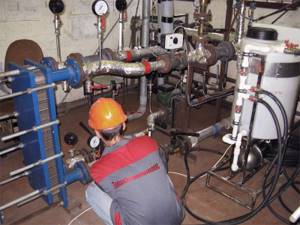
Installation of the elevator unit
It is worth immediately noting that installation and testing of the operation of the elevator unit and heating system is the prerogative of representatives of the service company. Residents of the house are strictly prohibited from doing this. However, knowledge of the layout of the elevator units of the central heating system is recommended.
When designing and installing, the characteristics of the incoming coolant are taken into account
The branching of the network in the house, the number of heating devices and the operating temperature are also taken into account. Any automatic elevator unit for heating consists of two parts
- Adjusting the intensity of the flow of incoming hot water, as well as measuring its technical indicators - temperature and pressure;
- Directly the mixing unit itself.
The main characteristic is the mixing coefficient. This is the ratio of the volumes of hot and cold water. This parameter is the result of precise calculations. It cannot be a constant, since it depends on external factors. The installation must be carried out strictly according to the diagram of the elevator unit of the heating system. After this, fine tuning is done. To reduce errors, a maximum load is recommended. This way the water temperature in the return pipe will be minimal. This is a prerequisite for precise control of the automatic valve.
After a certain period of time, scheduled checks of the operation of the elevator unit and the heating system as a whole are necessary. The exact procedure depends on the specific scheme. However, you can draw up a general plan that includes the following mandatory procedures:
- Checking the integrity of pipes, shut-off valves and devices, as well as compliance of their parameters with passport data;
- Adjustment of temperature and pressure sensors;
- Determination of pressure loss during coolant passage through the nozzle;
- Calculation of the displacement coefficient. Even for the most accurate heating scheme for an elevator unit, equipment and pipelines wear out over time. This amendment must be taken into account when setting up.
After this work has been completed, the automatic central heating elevator unit must be sealed to prevent tampering.
You cannot use homemade schemes of elevator units for central heating systems. They often do not take into account the most important characteristics, which can not only reduce operational efficiency, but also cause an emergency.
What is an elevator unit of a heating system?
Multi-storey buildings, high-rise buildings, administrative buildings and many different consumers provide heat from combined heat and power plants or powerful boiler houses. Even a relatively simple autonomous system in a private home is sometimes difficult to adjust, especially if errors were made during the design or installation. But the heating system of a large boiler house or thermal power plant is incomparably more complex. There are many branches leaving the main pipe, and each consumer has different pressure in the heating pipes and the amount of heat consumed.
Pipe lengths vary and the system must be designed so that the furthest consumer receives sufficient heat. It becomes clear why there is coolant pressure in the heating system. Pressure moves water along the heating circuit, i.e. created by the central heating line, it plays the role of a circulation pump. The heating system must not allow imbalance when the heat consumption of any consumer changes.
In addition, the efficiency of heat supply should not be affected by the branching of the system. In order for a complex centralized heating system to operate stably, it is necessary to install either an elevator unit or an automated heating system control unit at each facility to eliminate mutual influence between them.
How is the thermal unit arranged?
In general, the technical structure of each heating point is designed separately depending on the specific requirements of the customer. There are several basic schemes for the design of heating points. Let's look at them one by one.
Thermal unit based on an elevator.
The scheme of a heating point based on an elevator unit is the simplest and cheapest. Its main drawback is the inability to regulate the temperature of the coolant in the pipes. This causes inconvenience for the end user and a large overconsumption of thermal energy in the event of thaws during the heating season. Let's look at the figure below and understand how this circuit works:
In addition to what is indicated above, the thermal unit may include a pressure reducer. It is installed on the feed in front of the elevator. The elevator is the main part of this scheme, in which the cooled coolant from the “return” is mixed with the hot coolant from the “supply”. The operating principle of the elevator is based on creating a vacuum at its output. As a result of this vacuum, the coolant pressure in the elevator is less than the coolant pressure in the “return” and mixing occurs.
Thermal unit based on a heat exchanger.
A heating point connected through a special heat exchanger allows you to separate the coolant from the heating main from the coolant inside the house. The separation of coolants allows for its preparation using special additives and filtration. With this scheme, there are ample opportunities to regulate the pressure and temperature of the coolant inside the house. This allows you to reduce heating costs. To have a clear idea of this design, look at the figure below.
The mixing of coolant in such systems is done using thermostatic valves. In such heating systems, in principle, aluminum radiators can be used, but they will last for a long time only if the coolant is of good quality. If the PH of the coolant goes beyond those approved by the manufacturer, then the service life of aluminum radiators may be greatly reduced. You cannot control the quality of the coolant, so it is better to play it safe and install bimetallic or cast iron radiators.
DHW can be connected in a similar way via a heat exchanger. This offers the same benefits in terms of hot water temperature and pressure control. It is worth saying that unscrupulous management companies can deceive consumers by lowering the hot water temperature by a couple of degrees. For the consumer, this is almost unnoticeable, but on a household scale it allows you to save tens of thousands of rubles per month.
Scheme development
At the initial stage, heating engineers work on the development of a heating scheme, carry out a series of calculations and achieve the same efficiency indicators of the heating system on all floors of the building. They draw up an axonometric diagram of the heating system, which is subsequently used by installers. Calculations carried out correctly by specialists guarantee that the designed heating system will be characterized by optimal coolant pressure, which will not lead to water hammer and interruptions in operation.
Inclusion of an elevator unit in the heating scheme
The central heating scheme for an apartment building, prepared by heating engineers, assumes that the radiators located in the apartment will receive coolant at an acceptable temperature. However, at the exit from the boiler room, the water temperature can exceed 100 degrees. To achieve cooling of the coolant by mixing cold water, the return and supply lines are connected by an elevator unit.
A reasonable heating elevator design allows the unit to perform a number of functions. The main function of the unit is direct participation in the heat exchange process, since the hot coolant entering it is dosed and mixed with the injected coolant from the return. As a result, the unit allows you to achieve optimal results in matters of mixing hot coolant from the boiler room and cooled water from the return. After this, the prepared coolant at the optimal temperature is supplied to the apartments.
Design features of the circuit
An effective heating system in an apartment building, the design of which requires competent calculations, also implies the use of many other structural elements. Immediately after the elevator unit, special valves are integrated into the heating system to regulate the supply of coolant. They help control the heating process of the entire house and individual entrances, but only employees of service utility companies have access to these devices.
In the heating circuit, in addition to thermal valves, more sensitive devices are used to regulate and adjust the heating.
We are talking about devices that increase the performance of the heating system and allow for maximum automation of the home heating process. These are devices such as collectors, thermostats, automation, heat meters, etc.
Malfunctions of heating elevators
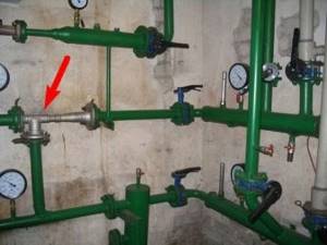
The diagram of the elevator heating unit may have faults that are caused by a breakdown of the elevator itself (clogging, an increase in the diameter of the nozzle), clogging of mud traps, breakdown of fittings, or violations of the regulator settings.
Small elevator heating unit
The breakdown of an element such as a heating elevator device can be noticed by the way temperature differences appear before and after the elevator. If the difference is large, then the elevator is faulty; if the difference is insignificant, then it may be clogged or the nozzle diameter may be increased. In any case, diagnosis of the breakdown and its elimination should only be carried out by a specialist!
Devices installed on the lower floors will overheat, and those on the upper floors will not receive enough heat. Such a malfunction, which the operation of the heating elevator undergoes, is eliminated by replacing it with a new nozzle with the calculated diameter.
Maintenance of the elevator heating unit
Clogging of the sump in a device such as an elevator in a heating system can be determined by the increase in the pressure difference, monitored by pressure gauges before and after the sump. Such clogging is removed by discharging dirt through the drain valves of the sludge tank, which are located in its lower part. If the blockage is not removed this way, then the mud trap is disassembled and cleaned from the inside.
Possible malfunctions and repairs
Despite the reliability of the equipment, in some cases the elevator heating unit may malfunction. Hot coolant and increased pressure quickly find vulnerable areas and provoke failure of this device. This inevitably happens if individual elements are poorly assembled, the nozzle size is calculated incorrectly, or due to blockages.
Noise in the heating pipe . The elevator heating unit may create noise during operation. If this is noted, it means that unevenness or cracks have appeared at the nozzle outlet during operation.
The reason for the formation of these defects is the distortion of the nozzle, which is caused by the supply of hot water under high pressure. This can happen if excessive pressure is not throttled by the flow regulator.
Incorrect temperature
The quality operation of the heating elevator can be questioned if the temperature on the input and output circuits differs significantly from the temperature graph. Most likely, the reason for this is the oversized nozzle.
Incorrect coolant flow
A faulty throttle can lead to a change in coolant flow in contrast to the design indicator.
This violation can be easily determined by changing the temperature in the supply and return pipes. The problem can be solved by repairing the flow regulator.
Faulty parts of the unit
If the connection diagram of the heating system to the external main is independent, then the cause of poor elevator operation can be caused by faulty water heating elements, circulation pumps, protective and shut-off valves, various leaks in equipment and pipes, and failure of regulators.
The main reasons that negatively affect the principle of operation and design of pumping equipment include the destruction of elastic membranes in the joints of the shafts of the electric motor and the pump, wear of bearings and failure of the seats under them, the appearance of cracks and irregularities in the housing, and leakage of seals. All of the above breakdowns can only be eliminated through repairs .
Poor operation of water heaters can be observed if the tightness of the pipeline is broken, sticking or destruction of the pipe assembly occurs. The problem can only be solved by replacing the pipes.
Blockages and pollution
Blockages are one of the most common causes of poor-quality heat supply. Their appearance is caused by dirt getting into the heating system if the dirt filters do not cope with their task. Corrosion build-ups inside the pipeline can also increase the problem.
The level of filter contamination can be determined by the pressure gauges that are installed near the filter and behind it. A strong pressure drop can confirm or refute the assumption about the level of contamination. To clean the filters, it is necessary to remove dirt through the drain valves , which are located at the bottom of the housing.
Any malfunctions in the heating equipment and pipes system must be corrected immediately!
Any comments that do not affect the operation of the heating system must be recorded in special documentation ; it must be included in the plan for capital or routine repairs of equipment. Troubleshooting must be done in the summer before the heating season.
Features of the operation of central heating stations, installation of heating points
The heating system is fed by the return pipeline of the heating network. Heat sources and thermal energy transport systems The heat source for TPs are heat generating enterprises, boiler houses, and combined heat and power plants.
Water from the external water supply network is supplied to the DHW heater.
Compensation for the decrease in pressure level is carried out through a group of pumps. Viewed: The DHW circuit can be designated as single-stage, independent and parallel.
Correction mode is automatic. Often, heat from the domestic hot water system is used by consumers for partial heating of premises, for example bathrooms in multi-apartment residential buildings. The flow of hot mains water to the 2nd stage heater is controlled by the temperature controller (thermal relay valve) depending on the water temperature behind the 2nd stage heater.
We recommend: How to measure a phase zero loop
The schematic diagram of an individual heating point is approved. Heating points
Certificate for flushing and pressure testing of heating networks, heating systems and hot water supply systems. ITP for heating, hot water supply and ventilation. Project documentation with all necessary approvals
All this equipment must operate exclusively in automatic mode, so it is critically important to correctly set up the entire set of equipment for work in a particular home
Central heating stations should be located on the boundaries of microdistricts between the main, distribution networks and quarterly ones. One of them is the heating system. If there is a central heating point in each individual building, it is necessary to install an ITP, which performs only those functions that are not provided for in the central heating point and are necessary for the heat consumption system of a given building.
This device can be represented as a container. But the cost of such a device is much higher, although its use is more economical. Heat consumption is controlled and taken into account. After the elevator, the return line will also be counted.
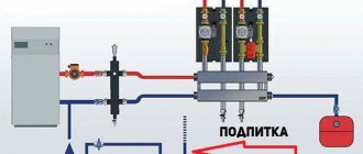
After the elevator unit, the mixed coolant is supplied to the heating system of the building. The installation company must be a member of the SRO. Further, as the most common, we consider a TP with a closed hot water supply system and an independent connection circuit for the heating system. Creating a schematic diagram of an individual heating point in AutoCAD P&ID
Design and principle of operation
The elevator mixes very hot water from the supply line and cool water from the return line. The heating elevator operates according to Bernoulli's law, sucking cooled coolant into the chamber due to a pressure difference and mixing it with hot fluid in a certain proportion for injection into the heating system. By mixing cold and hot coolant, the temperature of the working fluid is reduced to an acceptable level, its volume increases significantly, and the pressure stabilizes. Without an elevator, the operation of the heating system is impossible - by increasing the volume of liquid, it increases efficiency, maintains pressure, distributes heat evenly, and smoothes out sudden temperature changes. Without it, there would be cold radiators on the upper floors.
Centralized hot water supply systems (DHW) receive heated water from thermal power plants or boiler houses using natural gas, liquid or solid fuel. DHW systems are of closed and open type. In a closed system, water flows to the consumer from a heat exchanger. The advantages of a closed system are that hot water can be used for cooking and defrosting food. In an open system, water is supplied to the consumer directly after being processed in a steam turbine. This water should not be consumed as food - it contains polymer additives, rust, bacterial iron and other chemicals.
An adjustable elevator allows you to control the parameters of the heating system of a house equipped with electronic meters. They transmit the temperature outside, indoors, in the supply pipeline, and in the return pipeline to the elevator controller. The cone nozzle contains a throttling needle. The controller, which controls the mixing of cold and hot water, uses a servo drive to move the throttling needle inside the cone nozzle. Structurally, the needle elevator is made in the form of a casing; a throttle needle moves inside. The electric drive rotates a toothed gear, which moves the throttle needle, which increases or decreases the fluid flow until the nozzle opening is almost completely blocked. Advantages - the possibility of remote control of heating from the control panel of the thermal power plant. Disadvantages - whistling sound during operation.
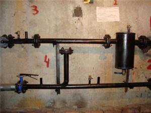
Thermal elevator unit number 3 is the most commonly used budget option in practice to ensure the operation of the hot water supply system of an apartment building or cottage. Maintaining constant parameters of the coolant occurs by mixing cooled water from the return pipeline into the hot coolant. This automatic regulator allows you to maintain constant temperature and pressure in the central and local heating system without connecting to the electrical network.
Legend:
- shut-off valves;
- sump;
- water jet elevator;
- membrane pressure gauge;
- alcohol thermometer.
Characteristics of the thermal elevator unit UTE-3:
- elevator nozzle diameter – 5 mm;
- diffuser diameter – 25 mm;
- weight – 19 kg;
- input flange DN1 – 50;
- offset flange DN2 – 80;
- output flange DU3 – 80;
- construction length – 62.6.
What is an elevator unit?
The elevator unit of the heating system is a device of a certain type that performs the functions of an injection or water-jet pump. The main tasks are to increase the pressure inside the heating system, increase the pumping of coolant through the network, and increase volume growth.
A durable thermal unit can transport significantly overheated coolant, which is economically beneficial. For example, one ton of water heated to +150 C contains much more thermal energy than the same volume with indicators of +90 C. The use of a thermal unit ensures rapid movement of the carrier through the system, without turning the liquid substance into steam - this property is constantly explained maintained pressure that keeps the carrier in an aggregate liquid state.
Operating principle and unit diagram
Algorithm for the operation of the elevator jumper:
- The heated coolant passes through the pipe in the direction of the nozzle, then under pressure the flow accelerates and the effect of a water-jet pump is started. Therefore, while water passes through the nozzle, the circulation of the media in the system is ensured.
- At the moment the liquid passes through the mixing chamber, the pressure level decreases to normal and the jet, entering the diffuser, provides a vacuum in the mixing chamber. According to the ejection effect, the coolant with an increased pressure indicator carries water through the jumper, which returns from the heating network.
- Mixing of the cooled and heated flow occurs in the heating elevator chamber, therefore, when leaving the diffuser, the flow temperature drops to +95 C.
Having considered what a heating unit is in an apartment building and the principle of operation of an elevator, you should know that for the normal functionality of the unit it is important to ensure the proper pressure difference in the main and return lines. The difference in indicators is needed to overcome the hydraulic resistance of the heating system in the house and the device itself
Externally, the elevator looks like a large tee made of metal pipes, equipped with connecting flanges at the ends. But if you look at the drawing, the structure of the thermal unit elevator from the inside is more complex:
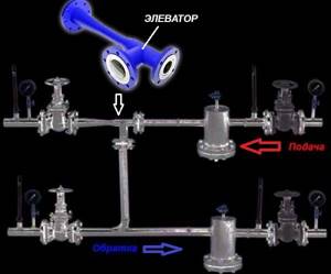
- the left pipe looks like a nozzle tapering to the calculated diameter;
- immediately behind the nozzle there is a mixing chamber cylinder;
- connection of the return line is achieved through the lower pipe;
- the pipe on the right is an expansion diffuser that directs hot water into the heating system.
A detailed diagram of the elevator heating unit is required when connecting the system. The connection is made as follows: the left pipe is to the supply line of the central network, the bottom pipe is to the pipeline with the return flow. Shut-off valves must be installed on both sides, supplemented with a mesh filter, which is needed to filter out large particles and inclusions. The design of the heating point is also complemented by pressure gauges, thermometers and heat meters.
Advantages and disadvantages of a thermal unit
Despite the obsolescence of the equipment, the simplicity of the design and low cost explain the demand for the heating elevator. The device does not need to be connected to the mains; it operates independently of energy. Many users argue that the scheme is irrational and if the efficiency of the device is low (up to 30%), the heating of the coolant should be reduced by abandoning the unit.
But if you remove the heating elevator, then the diameter of the main pipes will have to be significantly increased in order to ensure normal coolant flow at a lower temperature, and this will lead to additional costs. Therefore, it is premature to abandon the jet pump.
The disadvantages include the inability to control the water temperature, but when using devices with adjustable nozzle diameter, the minus is leveled out. Adjusting the nozzle will help control the speed of the supplied coolant, change the vacuum parameters in the mixer chamber and, as a result, control the water supply temperature.
What is a “heating network” and a “heating unit”
The home heating network is a set of pipelines that provide heat to each living space. This is a complex system that consists of two heat pipes: hot and cooled.
The list of tasks performed includes:
- monitoring the condition of the heat source;
- monitoring the condition of water and heat pipelines;
- registration of data from metering devices.
Types of heating units
In multi-storey buildings, two types of heating units are used.
Single-circuit provides a direct connection to hot water supply pipes, that is, the heat pipes are connected using an elevator. In high-rise buildings, the heating network is quite extensive, but most of the equipment is located in the basement.
Next, we will consider in more detail the principle of operation of a single-circuit thermal unit. Due to its design, namely the presence of an elevator, and low cost, it is used most often. For companies that install heating equipment and heating units, it is more profitable to use elevator units that are outdated and do not require careful attention.
Device
The single-circuit thermal unit is designed most simply. As already mentioned, it consists of a pipe extending from the heat source and a “cold” pipe, which are connected using an elevator. Also on the pipes there are filters and measuring instruments that monitor the flow, temperature of the coolant and pressure in the pipes.
Filtration equipment is installed, since the entire heating system reacts quite negatively to dirt and sediment in the coolant. Over time, it needs to be cleaned or replaced.
Installing meters has some nuances:
- placed on a pipe with “reverse” heat;
- it must be located as close as possible, as realistically as possible, to the heat source;
- setting parameters (required amount of heat per hour, day).
Operating principle
In this paragraph we will tell you what processes occur inside the elevator heating unit.
The in-house heating system can be disconnected from the city heating system using valves. Such actions are carried out during repair work and for general prevention. For such cases, there are special valves on the pipes designed to remove water from the system.
The use of a single-circuit unit has both advantages and disadvantages.
The advantages of such a heating unit are:
- ease of use;
- rare breakdowns;
- relative cheapness of components and their installation;
- completely mechanized and does not depend on external energy sources.
The main negative aspects:
- for each heat pipeline, personal calculations of parameters are required to select an elevator;
- the pressure in each pipe should be different;
- manual adjustment only;
- Who installs and maintains the heating unit.
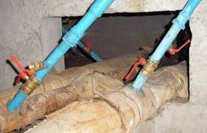
In houses with a large number of apartments there is a heat and hot water supply system from the city, which is located in the basement. Such a heating system requires preventive maintenance. The “weakest link” is the filters, or mud collectors, which need to be monitored and cleaned (all the dirt from the coolant accumulates in them).
This work is done, or at least should be done, by mechanics from the housing and communal services authorities who service the building. Since the heating center is complex and dangerous to operate, intervention by strangers is under no circumstances allowed, and diagnostics and repairs are allowed only to specially trained personnel.
Diagrams of thermal units
If we talk about the schemes of heating points, it should be noted that the most common types are the following:
Thermal unit is a circuit with a parallel single-stage hot water connection. This scheme is the most common and simple. In this case, the hot water supply is connected in parallel to the same network as the heating system of the building. The coolant is supplied to the heater from the external network, then the cooled liquid flows in the reverse order directly into the heat pipe. The main disadvantage of such a system, compared to other types, is the high consumption of network water, which is used to organize hot water supply.
Diagram of a heating point with a sequential two-stage connection of hot water. This scheme can be divided into two stages. The first stage is responsible for the return pipeline of the heating system, the second - for the supply pipeline. The main advantage of thermal units connected according to this scheme is the absence of a special supply of network water, which significantly reduces its consumption. As for the disadvantages, this is the need to install an automatic control system to configure and adjust the heat distribution. This connection is recommended to be used if the ratio of the maximum heat consumption for heating and hot water supply is in the range from 0.2 to 1.
Thermal unit is a circuit with a mixed two-stage connection of a hot water heater. This is the most universal and flexible connection scheme. It can be used not only for normal temperature schedules, but also for elevated ones. The main distinguishing feature is the fact that the heat exchanger is connected to the supply pipeline not in parallel, but in series. The further principle of the structure is similar to the second scheme of the heating point. Thermal units connected according to the third scheme require additional consumption of network water for the heating element.
Schematic and working diagram of the elevator.
Enterprises of the elevator industry include granaries of various types (mainly elevators and mechanized warehouses with working mechanization towers), workshops and plants for the preparation of seeds of various crops. These enterprises are typical representatives of flow production systems (PPS). On technological diagrams, in a laconic and expressive language of images and specified conventions, a very accurate picture in engineering terms is painted, giving a complete picture of the technological capabilities of the enterprise. Schematic diagrams reflect the relationship of the main machines, operational and storage tanks and storage tanks involved in various stages of the technological process. Working diagrams represent a concrete schematic diagram of the movement of grain and waste. Its difference from the fundamental one is in indicating the number, brand, numbering and technical characteristics of machines, mechanisms and devices, the number, numbering and capacity of bunkers and silos. Any design begins with making fundamental decisions. The design of elevator industry enterprises begins with drawing up schematic diagrams of the main production facilities included in the enterprises. Such objects can be: complexes of elevator structures (reception and release devices, work building and silo buildings, grain dryers, waste shops); complexes of structures for mechanization towers and drying and cleaning towers (reception and release devices, working towers, grain warehouses, mini-elevators, etc.), seed cleaning and corn calibration plants with departments for receiving and pre-cleaning, temporary storage, drying and cleaning of seeds, seed storage facilities. Getting started to design, based on the initial requirements, they determine the composition of the complex, i.e., they decide with the help of which structures and devices the specified operations will be performed. Then they draw up schematic diagrams of these structures and devices and link them with transport connections into a single system that generally solves the technological problem assigned to the complex. By combining these complexes in accordance with technology requirements, if necessary, they ultimately create a schematic diagram of the entire enterprise. Schematic diagrams are the basis for subsequent process design operations: selection and determination of the composition of the main equipment, determination of the dimensions of the industrial building in plan, placement of equipment on plans, determination floor heights, placement of equipment on cuts, carrying out communications of products, drawing up a working diagram of the movement of grain and products. The technological part developed in this way serves as the basis for the development of other parts of the working project. The schematic diagram is much simpler than the working one and it is easier to remember, which is very important in the learning process. The circuit diagram can be implemented in two ways:
1) all positions included in the diagram are indicated by conventional symbols; the meanings of these symbols, if they are not generally accepted, are explained in the text or on the diagram sheet;
2) the names of positions are written in rectangles or other geometric shapes.
PROCEDURE FOR DRAFTING A PRINCIPLE DIAGRAM.
Let's consider the procedure for drawing up a schematic diagram using the example of a production line: mechanized warehouses with a working cleaning tower (CWT). We build the diagram in the following sequence (in the figure under consideration, the numbers indicate the position numbers, and not the sequence of constructing the diagram): 1) conventionally in the form of a rectangle we designate the grain warehouse; 2) since it is mechanized, we depict the upper (loading) conveyor 6 with a dump cart and the lower (unloading) conveyor 8; 3) since the grain must be lifted onto the upper conveyor, we provide an elevator 3; 4) for receiving grain from vehicles - a receiving device , which necessarily includes a receiving hopper / and a receiving conveyor 2;
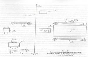
5) to clean the grain in the flow, we include separator 5 in the circuit; 6) for weighing grain at each operation, we provide for the installation of automatic scales 4 immediately after the elevator; 7) we release the grain into the cars using conveyor 9; 8) we number the positions and provide their decoding; 9) we draw lines of technological connections between positions (Fig. 2), choosing the optimal options for performing the provided operations. Reception of grain with in-line cleaning is carried out in the following sequence: receiving hopper 1, receiving conveyor 2, elevator 3, automatic scales 4, separator 5, elevator 3, scales 4, upper conveyor 6, warehouse 7. Loading grain into wagons is carried out in this sequence : warehouse 7, lower conveyor 8, elevator 3, scales 4, release conveyor 9, car 10.
Since a direct connection was provided between the equipment of the production line using grain pipelines (lines in the diagram), the productivity of the transporting and processing equipment should be the same. The compiled schematic diagram of the production line allows you to perform not only the provided operations, but also additional ones, such as receiving grain from vehicles without in-line cleaning (after weighing 4, the grain is immediately sent to the upper conveyor 6); re-cleaning of grain (we move grain from warehouse 7 sequentially through positions 8, 3, 4, 5, 3, 4, 6 to
Prevention of dandruff in children
To reduce the likelihood of dandruff, the child must follow the rules of personal hygiene - regularly wash his hair with high-quality shampoo, do not wear other people's hats and use a personal comb.
The appearance of dandruff in a child can be avoided if parents take care of the following points:
- Maintain personal hygiene - teach your child to use only his own comb and wear only his own hat, without lending these items to friends for use.
- To wash your hair regularly, use only high-quality shampoos for children. Wash your hair with warm, not hot water.
- Wear your child a hat in hot and cold weather. Do not buy your child a hat that is too tight.
- Monitor the child’s health status and promptly treat identified diseases.
- Ensure a normal, calm microclimate in the family and eliminate stressful situations for the child.
- After dandruff treatment, treat or throw away old combs. If it is not possible to purchase new hats for the child, then you should treat them with vinegar (in a plastic bag for 24 hours) or boil them.
- Provide the child with a balanced diet, adherence to a daily routine and sufficient time in the fresh air.
In addition to these measures, it is important to wash your child’s hair properly. How to do this, Elena Malysheva tells in the program “Live Healthy!”
About the heating system
If we talk about multi-apartment buildings, then they often have centralized heating installed, which supplies heat to all living spaces.
In country, private houses, autonomous heating systems are more common, made, in some cases, from cross-linked polyethylene pipes for heating.
But whatever heat supply system you have, it requires proper use, care, and careful attention.
One of the main elements of the heating system is the elevator unit.
Most people do not know about such a unit, but we will try to correct this by providing all the necessary information in this article.
This detail is present in any heating system, including modern ones, with heated floors (watch the video of the installation of cross-linked polyethylene pipes here), the elevator can be seen if you go into the basement.
But in order to appreciate its purpose, it is necessary to understand the heat supply circuit in any heating system.
So, the main source of heat is hot water, it is supplied to the house through a pipeline.
There is not one pipeline, but two, each of which performs its own important function:
- one supplies hot water to the building from the boiler room to the house;
- There is also a return pipeline that supplies the used coolant (cooled water) back to the boiler room.
Only hot water can enter the building's heating system from the boiler room's heat chamber. At the entrance to the thermal unit there is a special shut-off valve or a steel ball valve.
The second option is more reliable and modern; in new buildings, it is usually used.
Next, the hot water moves depending on how hot it is.
There are standards for water temperature, it must have one of the above temperatures:
- 95/70 degrees;
- 130/70 degrees;
- 150/70.
If the coolant is heated to a temperature below 95 C, it will be directed evenly throughout the system.
For this purpose, there are special collectors that regulate the distribution of water using balancing taps.
Thermal distribution point of the building
Heating engineers recommend using one of three temperature modes for boiler operation. These modes were initially calculated theoretically and underwent many years of practical application. They ensure heat transfer with minimal losses over long distances with maximum efficiency.
Thermal conditions of a boiler room can be defined as the ratio of the supply temperature to the return temperature:
- 150/70 – supply temperature is 150 degrees, and return temperature is 70 degrees.
- 130/70 - water temperature 130 degrees, return temperature 70 degrees;
- 95/70 - water temperature 95 degrees, return temperature - 70 degrees.
In real conditions, the mode is selected for each specific region based on the winter air temperature. It should be noted that high temperatures, especially 150 and 130 degrees, cannot be used for heating premises in order to avoid burns and serious consequences in case of depressurization.
The temperature of the water exceeds the boiling point and it does not boil in the pipelines due to the high pressure. This means that it is necessary to reduce the temperature and pressure and ensure the necessary heat extraction for a particular building. This task is assigned to the elevator unit of the heating system - special heating equipment located in the heat distribution point.
Control
We present the procedure for performing some operations related to the operation of the elevator.
Start heating
If the system is full, you just need to open the house valves and circulation will begin.
The instructions for starting a reset system are somewhat more complicated.
- The discharge on the return line opens and the discharge on the supply line closes.
- Slowly (to avoid water hammer) the upper house valve opens.
- After clean, air-free water flows into the discharge, it closes, after which the lower house valve opens.
Work without nozzle
When the return temperature is catastrophically low during the peak of cold weather, it is practiced to operate the elevator without a nozzle. The system receives coolant from the route, not the mixture. The suction is suppressed with a steel pancake.
Differential adjustment
If the return flow is too high and it is impossible to quickly replace the nozzle, adjusting the differential with a valve is practiced.
How to do it yourself?
- The supply pressure is measured, after which the pressure gauge is placed on the return line.
- The inlet valve on the return line closes completely and gradually opens with pressure control using a pressure gauge. If you simply close the valve, its cheeks may not completely move down the stem and will slide down later. The price of the wrong procedure is guaranteed defrosted access heating.
No more than 0.2 atmospheres of difference should be removed at a time. The return temperature is re-measured a day later, when all values have stabilized.