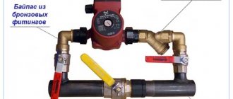
About the features of choosing a circulation unit
A forced circulation heating system will work properly provided that the performance and some other parameters of the pump are correctly selected. First of all, you should clarify how much coolant the product can pump in a specific period of time.
Initially, it is not advisable to purchase a pump model with a large supply of performance characteristics. Firstly, the cost of the device will be too high, so you will have to spend a significant part of the budget. Secondly, the device will consume excess energy, since as power increases, its consumption also increases.
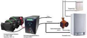
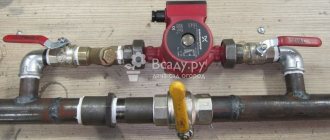
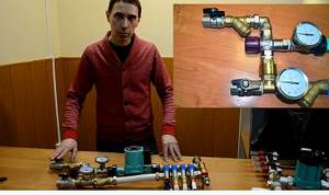
It is recommended to connect backup power to the pump
Last but not least, when choosing, you should take into account the factors of comfort and quality characteristics. For a quiet stay, it is, of course, better to purchase a device that does not create a lot of noise and is durable. These requirements are usually met by products from trusted manufacturers that have been on the market for a long time.
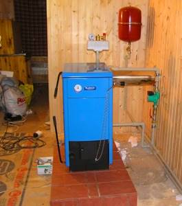
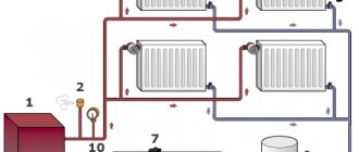
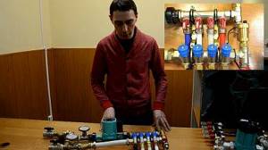
The device is integrated into the heating system of a private house
There is a common formula for calculation:
Q = N / (T2-T1) x K.
In this formula:
- Q stands for performance,
- T1 and T2 are the temperature of the coolant in the pipes at the boiler inlet and outlet, respectively. The liquid outlet temperature is usually 90°C, and the inlet temperature is 70°C. N is the boiler power.
- K is a coefficient that takes into account the heat capacity of water or other coolant. For water this figure is 1.16.
In addition to the performance parameters of the circulation pump, other factors must be taken into account: energy consumption, operating pressure, noise, type, manufacturer. Also, when calculating, you need to take into account the hydraulic resistance of the system, which will differ depending on the number of heating radiators, the presence of convectors, and a heated floor system.
Calculating the required parameters manually is not always convenient. To do this easier and faster using a special calculator. Below is a calculator for calculating the performance of the circulation pump. With its help, you can take into account all the necessary parameters and make a calculation in a matter of minutes.
Calculation of head height
At the moment, the main data for selecting a circulation pump have been calculated, then it is necessary to calculate the coolant pressure, this is necessary for the successful operation of all equipment. This can be done like this: Hpu=R*L*ZF/1000. Parameters:
- Hpu is the power or head of the pump, which is measured in meters;
- R is denoted as loss in supply pipes, Pa/M;
- L is the length of the heated room contour, measurements are taken in meters;
- ZF serves to represent the drag coefficient (hydraulic).
The diameter of the pipes can vary greatly, so the R parameter has a significant range from fifty to one hundred and fifty Pa per meter; for the location selected in the example, the highest R value must be taken into account. The correct length of the system is not so easy to determine; it is completely repelled depending on the size of the heated room. All indicators of the house are summed up and then multiplied by 2. With a house area of three hundred meters square, let’s take, for example, the length of the house is thirty meters, the width is ten meters, and the height is two and a half meters. In this outcome: L=(30+10+2.5)*2, which is equal to 85 meters. The easiest coefficient is resistance ZF is determined as follows: if there is a thermostatic valve, it is equal to 2.2 m, if not, 1.3. We take the biggest one. 150*85*2.2/10000=85 meters.
Water heated floor system: how does it work?
The system includes the following mandatory components:
- heat source (boiler, central heating riser);
- coolant (water, antifreeze, oil, etc.);
- heating pipes;
- insulation;
- control and distribution device;
- circulation pump.
The coolant circulates through an extensive network of pipelines located on the floor under the covering. The heat source is usually a gas boiler.
The use of water floors in apartments with a heat source supplied centrally through a riser is allowed in houses with apartment-by-apartment horizontal heating distribution.
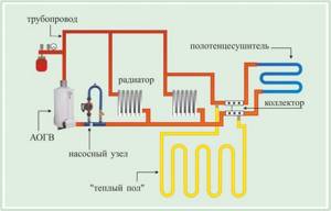
Warm floor arrangement diagram
In order to heat the floors equally, the pipes are placed at a small distance from each other (100-200 mm). Near the walls, the distance between the pipes is left less than in the center of the room. Pipe layout is carried out according to two schemes:
- snake – associated with a slalom or zigzag course;
- snail - resembles a spiral.
The coolant, heated to a temperature of 35-45 degrees, passes through the pipeline and loses temperature. The optimal length of the pipeline (loop) is up to 120 m. This is enough to cover a room of up to 20 m2. For large rooms, several pipelines are installed. They are connected in parallel to the heat source through a collector, which is located in a special cabinet. It also installs shut-off and control equipment (pressure gauges, thermostats, drain valves, flow sensors, air valves), as well as pumps.
Recommendations for selecting a circulation pump. Calculation of pressure and productivity.
Pump capacity Q
To calculate the pump performance, you need to know one of the following parameters: a) heated area b) power of heat source A. If the heated area is known, you first need to calculate the required power of the heat source using the formula:
Qn = (Sn x Qsp) / 1000
, Where
Qn - required thermal power, in kW Sn - heated usable area of the building, and m2 Qsp - specific heat requirement of the building 70 W/m2 - for a building with more than 2 apartments 100 W/m2 - for detached buildings with 1-2 apartments A, B. Pump performance is calculated using the formula:
Qn = Qn / 1.16 x (tr - tx)
, Where
Qn - pump flow, in m3/h Qn - required thermal power, in kW 1.16 - specific heat capacity of water, in W x hour/kg x oK tr - water temperature at the outlet of the boiler, in °C tx - inlet water temperature to the boiler, in °C Temperature difference Δt = tr – tx depends on the type of heating system Δt = 20°K for standard heating systems Δt = 10°K for low-temperature heating systems Δt = 5°K for underfloor heating systems
Pump head N
The most important note: the pressure of the circulation pump depends not on the height of the building, but on the hydraulic resistance of the heating network. Therefore, it is necessary to calculate this resistance. The calculation is made using the formula:
Hн = (R x I + ΣZ) / (ρ xg)
, Where
Hn - pump pressure, in m If we are talking about an old building, most often we can talk about an approximate calculation of the parameters, since the documentation is unlikely to have been preserved. In this case, it is better to calculate using a different formula:
Hн = (R x I + ΣZ) / (1000)
, Where
Hn - pump pressure, in m R - friction losses in a straight pipe, in Pa/m I - total length of the pipeline to the farthest heating element, in m SF - safety factors for 1.3 - fittings / fittings 1.7 - thermostatic valves 1,2 – mixer / device preventing natural circulation It has been experimentally established that in a straight pipeline pipe a resistance of the order of R = 100:150 Pa/m occurs. This corresponds to the required pump pressure of 1.0:1.5 cm per meter of pipeline. The most unfavorable branch of the pipeline is determined between the heat source and the most distant radiator. The length, width and height are added and multiplied by 2: I = 2 x (a + b +h) To determine the resistance of all additional parts of the pipeline, you can use the safety factors ZF, calculated empirically. The values of these coefficients for fittings and fittings are approximately 30% of the losses in a straight pipe, that is: ZF1 = 1.3 If thermostatic valves are installed in the system, then the value of the overall safety factor will be as follows: ZF = ZF1 x ZF2 = 1.3 x 1.7 = 2.2 If there is a mixer in the system, then an additional safety factor should be taken into account in the calculations, that is: ZF = ZF1 x ZF2 x ZF3 = 1.3 x 1.7 x 1.2 = 2.6
Pump selection.
After calculations 1 and 2, the values of productivity and pressure should be obtained, which determine the operating point by which the pump model is selected. Each pump has its own hydraulic characteristic. The most optimal pump operation is in the middle third of the graph (very often this zone is highlighted with a thick line). It is very rare that the design point coincides with the hydraulic characteristic of the pump. Most often this point lies between the characteristics of the two pumps. When choosing a specific pump model, you do not need to choose a powerful one, since even a less powerful pump will fully provide the heating system.
Number of circulation pump speeds
Pump speed is the ability of the device to change productivity. It’s easy to find out about the presence of modes - the description will indicate not one power, but several (usually three).
In the same way, rotation speed and productivity are indicated in three options. For example: 70/50/35 W (power), 2200/1900/1450 rpm (rotation speed), head 4/3/2 m.
There are models that automatically change operating speed (and therefore productivity) depending on the ambient temperature.
To change the mode, there is a special switch on the pump body. It is recommended to set manual models to maximum power mode and reduce it if necessary. In automatic devices, you just need to remove the regulator from the lock.
The presence of speed modes is not only for increasing comfort. This is also justified economically. A regime device can save up to 40% of energy compared to a conventional one.
Making a mixing unit with your own hands
When constructing warm water floors, you can choose a ready-made model of a pumping and mixing unit. But if you want to make a budget knot with your own hands, then we will tell you in detail the step-by-step process.
Before you start work, you need to stock up on: a strainer, a three-way thermostatic and check valve, two thermometers, a circulation pump, an air vent, two tees, two drain and ball valves. And also, manifolds - for the supply pipeline with ball valves and for the return pipeline with regulators.
In addition, the number of loops of a warm water floor should be equal to the outlets on the collector.
Step-by-step assembly instructions:
We mount a mesh filter to the ball supply valve, after which we install a corner.

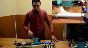
Screw the filter to the feed
We screw a three-way thermostatic mixing valve to the corner.

Installing a three-way valve
We screw a check valve to the mixer, to the side where the return line will be connected - without it, the unit will not work correctly.

Connecting the check valve
We install thermometers to the return and to the middle outlet of the mixing unit.

We fix the thermometers
We connect a circulation pump to the thermometer coming from the supply pipe. It is necessary that the straight distance from the thermometer to the pump, and from the pump to the collector, be equal and equal to 10 diameters of the supply pipe.
Next, we mount the collectors, which are fixed on a special bracket. We connect the supply manifold with ball valves to the pump, the return manifold will have control valves.
We install the collector group
We screw tees to the end outlet of the supply and return manifold, to which the air vent is attached.

Connecting the tees
We install an air vent.
We install a drain ball valve at the side outlets of both tees. They are necessary to fill or drain the system.

We connect a piece of polypropylene or metal-plastic pipe to the return manifold. Its size should be equal to the distance from the supply manifold to the thermometer.
We attach a piece of pipe to the return line
We place a second mesh filter between this section of pipe and the return thermometer.

Installing a second filter
We screw the ball valve to the check valve.
Connecting the return valve
The result was a simple, cheap model of a homemade pumping and mixing unit for heated floors.

Ready node
Knowledge needed for calculations
In order to correctly understand and produce a complete algorithm for calculating the circulation pump of a heating system, you should be able to correctly start from a certain value, the correctness of which will not raise doubts. To do this, you first need to open the passport of the room in which the equipment will be installed and find out its total area. For an example of calculation, we will take a private house with a total area of 300 square meters.
Next, you need to determine all the values that will be needed for the calculation, these are 3 main parameters:
- Qn shows the heat power (kilowatts);
- Qpu shows the power of pump movement (more precisely, this value will show V of the coolant supply for the selected room, measurements are taken in meters per hour)
- Hpu value shows the pressure power that is needed to overcome multidirectional systems
To calculate heat, you will need all these quantities. For each home, there are special standards that a heating source must have. In other words, a certain norm of formulas that is used further.
In order to find out the power, there is a formula: Qn=Sn*Qyd/100.
The total area of the proposed premises is known; it is three hundred square meters. The second indicator depends only on the type of building: in an apartment building the indicator is equal to seventy Watts per square meter, in the case used in the example (a separate building) it is one hundred Watts per square meter. Translating all the values into the formula, it turns out: 300*100/1000=30KW. As a result, it turns out that the power of the room heating device will be thirty kilowatts.
There is another method by which you can make the calculation. The size of the room to be heated, as well as the required power of the heating unit, can be found below:
- 5 KW - V premises of an obsolete building 70-150 sq.m, V premises of a new building 60-110 sq.m;
- 10 KW - V premises of an obsolete building 150-300 sq.m, V premises of a new building 130-220 sq.m;
- 20 KW - V premises of an obsolete building 320-600 sq.m, V premises of a new building 240-400 sq.m;
- 30 KW - V premises of an obsolete building 650-1000 sq.m, V premises of a new building 460-650 sq.m;
- 40 KW - V premises of an obsolete building 1050-1300 sq.m, V premises of a new building 650-890 sq.m;
- 50 KW - V premises of an obsolete building 1350-1600 sq.m, V premises of a new building 900-1100 sq.m;
- 60 KW - V premises of an obsolete building 1650-2000 sq.m, V premises of a new building 1150-1350;
Formula V of a building or apartment, V is calculated by multiplying its H by S. (V=S*H):
- V is the volume of the entire room;
- S is the total area that is heated;
- H is the height of the room;
In the example chosen, the height is 2.5 meters. The total total area in this case will be equal to the formula. 300*2.5=750 meters cubed. Based on the data above, this is exactly 30 kilowatts.