Features of heating systems equipped with a pump
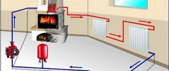
Country houses equipped with a separate heating system may be heated unevenly due to the heat energy being distributed across all rooms. The least amount of heat will reach those rooms that are located further from the boiler. To solve this problem, you can not only focus on creating new heating systems with a large-diameter pipeline, but also insert a pump into the heating system. currently present.
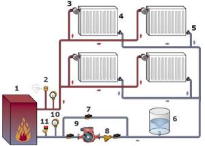
Typical circulation pump installation diagram: 1 - boiler, 2 - air vent, 3 - thermostatic valve, 4 - radiator, 5 - balancing valve; 6 - membrane tank, 7 - ball valve, 8 - filter, 9 - circulation pump, 10 - thermomanometer, 11 - safety valve.
Connecting a pump to a heating system is not as expensive a procedure as connecting a new pipeline.
At the same time, in this case, a dismantling procedure is applied to old heating systems, which cannot be a simple task. Installing a pump is much cheaper, especially since you can always do it yourself. The pump avoids the formation of air plugs inside the pipes, ensuring its normal circulation through the pipeline. With the help of a pump, temperature stabilization is achieved in each room of the house. The device as a whole serves to optimize the operation of the heating system of any residential premises.
Circulation pump wiring diagram.
The type of sealed throttleless pump for heating systems is the most common due to their simple operation and convenient design. The body of this type of pump is made of cast iron. In this case, it is possible to use plastic or steel as a material for a part such as a rotor. The operation of such devices is silent. In this case, there will be no need to replace gaskets in the heating system, which will be filled not with a cooling element and lubricant, but with water. During its entire service life, the unit will be characterized by high reliability. The main condition for this is the correct connection of the pump to the heating system.
Calculation of operating pressure in the circuit
Video
When choosing a circulation pump for a heating system, calculations must also be made based on such an indicator as the pressure inside the pipeline. To do this, you can use the relationship:
P = (R x L + Z) / pxq, where:
P – pressure value;
R – flow resistance for straight sections of the pipeline;
L – total length
Z is the value of flow resistance determined by the fittings, taps and other fittings used in the system;
р – value of coolant density at operating temperature;
q – value of free fall acceleration.
If there is insufficient data for calculation using the given formula, you can use the simplified relationship:
P = R x L x ZF, where
R is the value of flow resistance in a straight pipe section, approximately 100 - 150 pascals per 1 meter, expressed in a form convenient for calculation, it will be 0.01 - 0.015 meters per meter pipe section;
L is the total length of the pipeline; in a two-pipe heating scheme, both forward and return circuits are taken into account;
ZF – magnification factor, depending on the following indicators:
- for a system with ball valves, for which it is unusual to reduce the clearance of the pipeline, and with correctly selected fittings it is taken equal to 1.3;
- when using throttle or temperature control devices, its value will be 1.7.
Video
When choosing a circular pump for a heating system, calculating its characteristics appears to be a necessary procedure.
The practice of using circulation pumps makes it possible to select them without calculating the necessary parameters. Recommended parameters are shown in the table.
Table for empirical pump selection
Table 1.
| Heated area (m2) | Productivity (m3/hour) | Stamps |
| 80 – 240 | From 0.5 to 2.5 | 25 – 40 |
| 100 – 265 | Is the same | 32 – 40 |
| 140 – 270 | From 0.5 to 2.7 | 25 – 60 |
| 165 – 310 | Is the same | 32 – 60 |
Note: in the third column, the first number is the diameter of the pipes, the second is the lift height.
Video
Using the given data, you can select the right device for stable and long-term operation without much hassle.
Main manufacturers
Circular pumps for heating systems are produced by many European manufacturers with fairly high quality and a wide range.
Wilo company. The pumps of this concern, produced in Germany, occupy a fairly large place in the specialized market. They are distinguished by high quality and stable operation. Almost all models of this manufacturer are equipped with automatic and manual controls. Not only the rotor speed is adjusted, but also the release functions, including the amount of pressure in the system.
DAB company. This Italian manufacturer successfully competes with other suppliers to the Russian market, presenting centrifugal pumps for more than 40 years. A special feature of DAB products is the displays used on the control panel, which are very convenient for interacting with the installation and monitoring the work process.
Manufacturer Grundfos. The Danish company under this name has existed for more than 70 years, supplying the market with pumping equipment for various purposes. It should be noted that this manufacturer is clearly and has long been recognized in the specialized market. The fruitfulness and creativity of the company, which launches up to hundreds of new models of its products on the market every year, is impressive.
This manufacturer’s equipment for heating systems is marketed under the UPS label and the product line is intended for both domestic and industrial use. The main feature of circular pumps for heating is their suitability for operation in a very wide temperature range: from -25° to +110°C.
The UPS product line can operate using 3 performance modes.
Gilex company. A domestic manufacturer of circular pumps, successfully competing in the market with European companies.
The units are unpretentious in operation and can ensure active circulation of coolants of various densities in heating networks, which determines a wide selection of liquids, including transformer oil. They operate in 3 power modes, stepless adjustment. It compares favorably with its competitors in price level.
Conclusion
The choice of a circular pump for a heating system and its calculation will allow the consumer to make the optimal purchase for the actual conditions of a particular room.
The options for preliminary assessment of the necessary equipment proposed here allow you to confidently make such a choice. I wish you success!
What is a circulation pump and why is it needed?
A circulation pump is a device that changes the speed of movement of a liquid medium without changing pressure. In heating systems it is installed for more efficient heating. In systems with forced circulation it is a mandatory element, in gravity systems it can be installed if it is necessary to increase the thermal power. Installing a circulation pump with several speeds makes it possible to change the amount of heat transferred depending on the outside temperature, thus maintaining a stable temperature in the room.
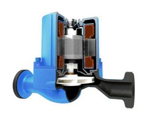
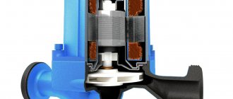
Cross-section of a circulation pump with a wet rotor
There are two types of such units - with a dry and wet rotor. Devices with a dry rotor have a high efficiency (about 80%), but are very noisy and require regular maintenance. Units with a wet rotor operate almost silently; with normal coolant quality, they can pump water without failure for more than 10 years. They have a lower efficiency (about 50%), but their characteristics are more than sufficient for heating any private home.
Where to put
It is recommended to install a circulation pump after the boiler, before the first branch, but on the supply or return pipeline it doesn’t matter. Modern units are made from materials that can withstand temperatures up to 100-115°C. There are few heating systems that work with a hotter coolant, so considerations of a more “comfortable” temperature are untenable, but if you feel safer, put it in the return line.
Can be installed in the return or direct pipeline after/before the boiler up to the first branch
There is no difference in hydraulics - the boiler, and the rest of the system; it makes absolutely no difference whether there is a pump in the supply or return branch. What matters is the correct installation, in terms of strapping, and the correct orientation of the rotor in space
Nothing else matters
There is one important point regarding the installation location. If the heating system has two separate branches - on the right and left wings of the house or on the first and second floor - it makes sense to install a separate unit on each, and not one common one - directly after the boiler. Moreover, the same rule remains on these branches: immediately after the boiler, before the first branch in this heating circuit. This will make it possible to set the required thermal conditions in each part of the house independently of the other, and also in two-story houses to save on heating. How? Due to the fact that the second floor is usually much warmer than the first floor and much less heat is required there. If there are two pumps in the branch that goes up, the speed of movement of the coolant is set much lower, and this allows you to burn less fuel, without compromising the comfort of living.
There are two types of heating systems - forced and natural circulation. Systems with forced circulation cannot work without a pump; systems with natural circulation work, but in this mode they have lower heat transfer. However, less heat is still much better than no heat at all, so in areas where electricity is often cut off, the system is designed as hydraulic (with natural circulation), and then a pump is installed into it. This gives high heating efficiency and reliability. It is clear that the installation of a circulation pump in these systems is different.
All heating systems with heated floors are forced - without a pump, the coolant will not pass through such large circuits
Forced circulation
Since a forced circulation heating system without a pump is inoperative, it is installed directly into the gap in the supply or return pipe (of your choice).
Most problems with the circulation pump arise due to the presence of mechanical impurities (sand, other abrasive particles) in the coolant. They can jam the impeller and stop the motor. Therefore, a mesh dirt filter must be placed in front of the unit.
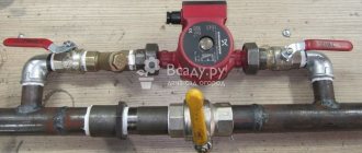
Installing a circulation pump in a forced circulation system
It is also advisable to install ball valves on both sides. They will make it possible to replace or repair the device without draining the coolant from the system. Turn off the taps and remove the unit. Only that part of the water that was directly in this piece of the system is drained.
Natural circulation
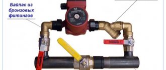
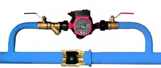
The piping of the circulation pump in gravity systems has one significant difference - a bypass is required. This is a jumper that makes the system operational when the pump is not working. One ball shut-off valve is installed on the bypass, which is closed the entire time the pumping is running. In this mode, the system operates as forced.
Installation diagram of a circulation pump in a system with natural circulation
When the electricity goes out or the unit fails, the valve on the jumper is opened, the valve leading to the pump is closed, and the system operates as a gravity system.
Installation features
There is one important point, without which the installation of the circulation pump will require rework: it is necessary to rotate the rotor so that it is directed horizontally. The second point is the direction of flow. There is an arrow on the body indicating which direction the coolant should flow. This is how you turn the unit so that the direction of movement of the coolant is “in the direction of the arrow”.
The pump itself can be installed both horizontally and vertically, just when selecting a model, make sure that it can work in both positions. And one more thing: with a vertical arrangement, the power (pressure created) drops by about 30%. This must be taken into account when choosing a model.
Recommendations for proper pump installation
To ensure convenient access for servicing the pump, the unit must be connected correctly. In practice, when installing a pump, the following basic installation rules should be taken into account:
After installing the circulation pump, it should always be accessible so that in the event of a breakdown, it can be easily repaired or replaced.
- Both sides of the pumping unit must be equipped with special ball valves, which are necessary when carrying out maintenance of the entire heating system or during the dismantling of the unit.
- It is necessary to equip the entire system with a filter in order to protect the device from exposure to small particles that lead to damage to the installation and its components.
- Since the water passing through the heating system is far from ideal, additional protection will be required for the pumps to function properly. Therefore, the heating bypass on top must be equipped with a valve, which must be installed. You can choose any valve: automatic or manual. Its purpose is to release air pockets formed in the pipes; its terminals should be directed clearly upward.
- Belonging to the type of wet models, the pump must be installed in a horizontal position so that it is completely immersed in water, and not just a separate part. Incorrect installation can cause damage to the working surface of the unit, and the installation will be pointless.
- To increase the operating potential of the structure, it is necessary to specially treat all fasteners and connections in the system with a sealing agent.
- It is necessary to ensure that the sequence is observed when connecting the pump and fasteners.
Impeller diameter correction
Obviously, the impeller diameter cannot be reduced while the pump is running. Compared to the throttle and bypass control methods, which can be carried out while the pump is running, correction of the impeller diameter must be carried out before installing the pump or during repair work. The following formulas show the relationship between impeller diameter and pump parameters:
Note that these formulas reflect the operation of an ideal pump. In practice, reducing the diameter of the impeller leads to a decrease in the efficiency of the pump, i.e. to reduce its efficiency. With a slight correction of the diameter DH2 > 0.8 • DH1, the efficiency will decrease by only a few percent. The level of efficiency reduction depends on the type of pump and its operating point.
As can be seen from the formulas, the ratios of changes in flow and pressure are equal to each other and equal to the square of the ratio of the impeller diameters. In this case, the working points are located on a straight line originating in the coordinate system at the point (0, 0). The ratio of power consumption before and after correction is equal to the ratio of diameters to the fourth power.
How the unit works
The principle of operation of the circulation unit is very similar to the operation of a drainage pump. If this device is installed in a heating system, it will cause movement of the coolant by capturing liquid on one side and pumping it into the pipeline on the other side
The principle of operation of the circulation unit is very similar to the operation of a drainage pump. If this device is installed in a heating system, it will cause the movement of the coolant by capturing liquid on one side and pumping it into the pipeline on the other side. All this happens due to the centrifugal force, which is formed during the rotation of the wheel with blades. During operation of the device, the pressure in the expansion tank does not change. If it is necessary to increase the coolant level in the heating system, install a booster pump. The circulation unit only helps water overcome the resistance force.
The device installation diagram looks like this:
- A circulation pump is installed on the pipeline with hot water coming from the heater.
- A bypass valve is installed on the section of the line between the pumping equipment and the heater.
- The pipeline between the bypass valve and the circulation pump is connected by a bypass to the return pipeline.
This installation scheme involves the release of coolant from the device only if the unit is filled with water. To keep the liquid in the wheel for a long time, a receiver equipped with a check valve is built at the end of the pipeline.
Circulation pumps used for domestic purposes can develop a coolant speed of up to 2 m/s, and units used in the industrial field accelerate the coolant up to 8 m/s.
It’s worth knowing: any type of circulation pump operates from the mains. This is quite economical equipment, since the motor power for large industrial pumps is 0.3 kW, and for household appliances it is only 85 W.
How electronically controlled circulation pumps should work
Models with electronic heating type have two types of speed control: manual and automatic. Manual regulation involves setting the power of the device at the desired level. In this case, pressure drops are not corrected.
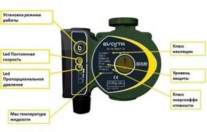
Photo 1. Control circuit for the DAB EVOSTA circulation pump with electronic control. Selecting the operating mode is done with one button.
In the case of automatic control, the reduction or increase in speed is carried out by the system itself and directly depends on the temperature in the pipeline. The autopilot itself determines the optimal level of performance and, if necessary, reduces energy consumption without reducing productivity.
Important! Automatic reduction of pump speed is only possible after hydraulic balancing of the system.
Source
Principles of installation and connection of the pump
To prepare the heating system for pump installation, first drain the heating fluid and clean the entire system if it is dirty. The system is filled with water only after the pipes are secured, after which they are carefully checked for any malfunctions for their further elimination. Using the central screw, excess air is removed from the system.
In order for the installed pump to interact with the cooled coolant and to extend its service life, the unit is mounted in the return line pipeline. When installed in a forced circulation system, the connection of the expansion tank should be made not to the main riser, but to the return pipeline.
Having positioned the pump strictly horizontally, it is attached to the pipes. As an additional device, the circulation pump can be installed in a natural circulation system. In this case, the pump must be equipped with a filter and a split thread. The diameter of the filter must match the diameter of the pump. Pressure operation of the system must be maintained by a conventional valve corresponding to the thread diameter of the unit. If you are using an open system, it will not be required.
After the pump is installed, a valve should be installed on the main and return pipelines. So that air can be discharged from the system, a special device is installed on the bypass.
Where it is planned to install the pump, a pipe is cut off and a special connection for shut-off valves is welded to it; it is installed before and after the pump unit. This must be done for ease of removal, cleaning and repair of the device. Having turned off the taps on the outlet and inlet pipes of the pump, turn off the heating boiler, then unscrew the nuts that secure the pump to the pipes.
The pump must be connected after starting the entire system and filling the pipes with water. There should be no air remaining in the pipes, so it is released each time before starting the pumping unit. To bleed air manually, use special valves installed on both sides of the pumping unit.
Power connection
The circulation pumps operate from a 220 V network. The connection is standard; a separate power supply line with a circuit breaker is desirable. The connection requires three wires - phase, neutral and ground.
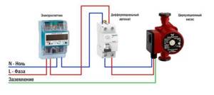
Circulation pump electrical connection diagram
The connection to the network itself can be organized using a three-pin socket and plug. This connection method is used if the pump comes with a connected power wire. It can also be connected via a terminal block or directly with a cable to the terminals.
The terminals are located under a plastic cover. We remove it by unscrewing several bolts and find three connectors. They are usually labeled (the pictograms are N - neutral wire, L - phase, and “ground” has an international designation), so it’s hard to make a mistake.
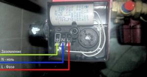
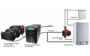
Where to connect the power cable
Since the entire system depends on the performance of the circulation pump, it makes sense to make a backup power supply - install a stabilizer with connected batteries. With such a power supply system, everything will work for several days, since the pump itself and the boiler automation “pulls” electricity to a maximum of 250-300 W. But when organizing, you need to calculate everything and select the battery capacity. The disadvantage of such a system is the need to ensure that the batteries do not discharge.
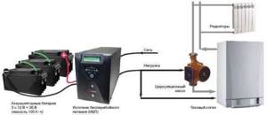
How to connect a circulator to electricity through a stabilizer
Hello. My situation, a 25 x 60 pump is located immediately after a 6 kW electric boiler, then the line from a 40 mm pipe goes to the bathhouse (there are three steel radiators) and returns to the boiler; after the pump, a branch goes up, then 4 m, down, rings a house of 50 sq. m. m. through the kitchen, then through the bedroom, where it doubles, then the hall, where it triples and flows into the boiler return; in the bathhouse there is a branch 40 mm up, it leaves the bathhouse and enters the 2nd floor of a house of 40 sq. m. m. (there are two cast-iron radiators) and returns to the bathhouse in the return line; there was no heat on the second floor; the idea of installing a second pump in the bathhouse for supply after the branch; the total length of the pipeline is 125 m. How correct is the solution?
The idea is correct - the route is too long for one pump.
Connecting the pump to the power supply
Connection to the power supply network can be done in two ways.
Direct connection
The first is standard, it is a direct connection of the power cable to an outlet with the desired type of voltage. Wherein:
- select a wire with a cross-section of at least 2 sq.m;
- conductors should be multi-stranded to reduce the likelihood of fractures when bending;
- The connection must be made using a grounding wire.
The specific cross-section of conductors should be selected based on the manufacturer’s recommendations and the rated power of the pump. The socket into which the device is connected should be located as close as possible to the installation point, and it is recommended to install RCDs and emergency shutdown circuit breakers between it and the pump.

It is recommended to install the grounding wire from a socket, the general structure of the electrical network. If this is not possible due to the outdated type of wiring, the pump can be connected to an external circuit.
Advice! If the pump voltage supply cable is located close to the heating network pipes and the coolant temperature exceeds 90 degrees, select a special heat-resistant wire to power the equipment.
UPS application
When the supercharger is operating, especially under load, power failures, power interruptions, and changes in input voltage parameters are possible. This may negatively affect the service life of the device, its efficiency, and lead to breakdowns. Therefore, if possible, it is worth using a connection diagram via an uninterruptible power supply.
When choosing an uninterruptible power supply model, a simple calculation is made. The basic conditions include the power of the circulation pump and the time during which its operation must be maintained. Based on the calculation results, the battery capacity or UPS model is selected. Many manufacturers of such equipment offer graphs and tables on their official resources that make it easy to determine the optimal power source option.
Advice! To power the circulation pump, it is recommended to use a UPS only with a sinusoidal output signal or close to it. The best results are shown by On-Line UPSs that provide zero response time and an ideal voltage curve.
What indicators to consider when choosing a pump
The correct choice of pump is based on the hydraulic resistance that the device itself overcomes in the process of creating the required pressure and force of water flow. For an optimally selected pump, the recommended power should be lower than the calculated one, by 10-15% of the calculated power. If the required power level is exceeded, the device may have a shorter service life, which will lead to its rapid wear. The noise level in the heating system may increase. If the power of the unit is less, then under these conditions the required amount of coolant will not be provided.
Diagram of the circulation pump.
The calculation of the pump power indicator is based on the diameter and length of the pipeline, the level of water temperature and coolant pressure. Ten meters of the heating system should be provided with half a meter of pressure using a pump. During the calculations, the coolant flow rate is compared with the level of water flow used in the boiler, the power of which is known. You should have data for calculations about how much water is needed for the normal operation of each of the rings of the heating system. Calculation of heat losses of a building can be made on the basis of tables of thermal conductivity of materials. The length of the heat pipeline and the number of heating radiators are also taken into account. The power of the battery is determined by the required amount of water per minute to ensure optimal heating of the room.
The circulation pump can be equipped with either an electronic or manual speed controller. If the pump shaft speed is set to the highest level, then the maximum operating coefficient of the device should be obtained.
Diagram and operating principle of a heating circulation pump
Forced circulation of the coolant accelerates the flow of liquid in the circuit, thereby reducing heat losses and saving fuel consumption. Thanks to the constant flow rate, the batteries are heated evenly. If there are no airy areas in the circuit, then the very last battery is just as hot as the first. The unit supplies hot water to the upper floors with constant pressure.
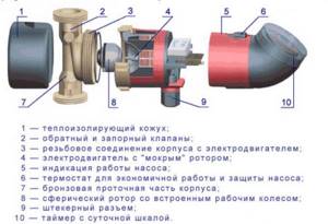
Circulation pump components:
- Durable housing, resistant to mechanical stress.
- Impeller to ensure pumping of coolant in the system.
- An electric motor to start the circuit into operation.
- A chamber that provides supply and pressure through pipes connected to the main line.
- Box with terminals for connecting automatic control of circulation pumps.
- The coolant enters the working chamber through the inlet pipe.
- The electric motor starts, turning on the impeller action. It captures the jet, increasing the pressure in the circuit.
- The increased flow rushes to the pipe connected to the main line and transfers the coolant into the pipe.
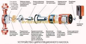
Pump device
Since the engine stator is energized, it is separated from the rotor using a glass made of stainless steel or carbon material
The main elements that make up the circulation pump are:
- housing made of stainless steel, bronze, cast iron or aluminum;
- rotor shaft and rotor;
- wheel with blades or impeller;
- engine.
Typically, an impeller is a structure of two parallel disks that are connected to each other by means of radially curved blades. One of the disks has a hole for liquid to flow through. The second disk secures the impeller to the motor shaft. The coolant passing through the engine acts as a lubricant and coolant for the rotor shaft where the impeller is fixed.
Since the engine stator is energized, it is separated from the rotor using a glass made of stainless steel or carbon material. The walls of the glass are 0.3 mm thick. The rotor is fixed on ceramic or graphite bearings for sliding.
Advantages of pumps with built-in frequency converter
The use of pumps with a built-in frequency converter is the optimal solution in many industrial sectors. And the main reason for this is to combine the advantages of a variable pump with the advantages obtained from combining a pump, a frequency converter, a PI controller and sometimes also a pressure sensor into a single unit, see fig. 4.4.1.
A pump with a built-in frequency converter can easily be called a system capable of solving various problems while saving energy. When it comes to interchangeability, pumps with built-in frequency converters are ideal as they can be installed in place of fixed pumps at no extra cost. To carry out such work, it is necessary to equip the pump with a built-in frequency converter, after which it is ready for operation. The installer only needs to set the set value (pressure), and the system is ready for operation.
What follows is a brief description of the advantages offered by pumps with a built-in frequency converter.
Ease of installation
Pumps with a built-in frequency converter are just as easy to install as unregulated pumps. Preliminary settings and adjustments of the pump are made at the manufacturer.
Energy optimization
Since the pump, motor and frequency converter are completely compatible with each other, the operation of such a system significantly reduces energy consumption.
Single supplier
A single supplier can provide a pump, a frequency converter and a sensor, which naturally makes it easier to determine the dimensions of the installation, select it, order it, as well as service and repair.
Wide range of operating parameters
Pumps with integrated frequency converter have a very wide range of operating parameters, which allows them to operate with great efficiency under different operating conditions and meet a wide range of requirements. Therefore, when replacing fixed pumps with a narrow operating range, you will need fewer variable pumps.
Why do you need a pump in a heating system?
Circulation pumps for heating private houses are designed to create forced movement of coolant in the water circuit. After installing the equipment, the natural circulation of liquid in the system becomes impossible; the pumps will operate in constant mode. For this reason, high demands are placed on circulation equipment regarding:
- Productivity.
- Noise insulation.
- Reliability.
- Long service life.
A circulation pump is needed for “water floors”, as well as two- and one-pipe heating systems. In large buildings it is used for domestic hot water systems.
As practice shows, if you install the station in any system with natural coolant circulation, the heating efficiency and uniform heating along the entire length of the water circuit increases.
The only disadvantage of this solution is the dependence of the pumping equipment on electricity, but the problem, as a rule, is solved by connecting an uninterruptible power supply.
Installing a pump in the heating system of a private home is justified both when creating a new one and when modifying an existing heating system.
Operating principle of the circulation pump
The operation of circulation pumps may differ slightly depending on the type of design, but the principle of operation remains the same. Manufacturers offer more than hundreds of equipment models, with various performance and control parameters. Based on the characteristics of the pumps, stations can be divided into several groups:
- According to the type of rotor - to enhance the circulation of the coolant, models with a dry and wet rotor can be used. The designs differ in the location of the impeller and moving mechanisms in the housing. Thus, in models with a dry rotor, only the flywheel, which creates pressure, comes into contact with the coolant fluid. “Dry” models have high performance, but have several disadvantages: a high level of noise is created from the operation of the pump, and regular maintenance is required. For domestic use, it is better to use modules with a wet rotor. All moving parts, including bearings, are completely enclosed in a coolant medium that serves as a lubricant for the parts that bear the greatest load. The service life of a “wet” type water pump in a heating system is at least 7 years. There is no need for maintenance.
- By type of control - the traditional model of pumping equipment, most often installed in small domestic premises, has a mechanical regulator with three fixed speeds. Regulating the temperature in the house using a mechanical circulation pump is quite inconvenient. The modules are distinguished by high power consumption. The optimal pump has an electronic control unit. A room thermostat is built into the housing. The automation independently analyzes the temperature in the room, automatically changing the selected mode. Electricity consumption is reduced by 2-3 times.
There are other parameters that distinguish circulation equipment. But to choose a suitable model, it will be enough to know about the nuances listed above.
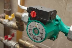
Technical characteristics of pumps for heating systems GRUNDFOS UPS 25–40
The base of the device is made entirely of cast iron. The drive design is made according to the “wet rotor” scheme. Thanks to this type of pump assembly, it is almost silent. It operates at three speeds, they are usually set depending on your heating system (that is, individually everywhere). The model name marking is deciphered as follows:
- Up — equipment type designation;
- S—pump speed switch;
- 25 — pipe diameter, mm;
- 40 is the highest pressure indicator.
Such a circulation device is small in size, which is why it does not require additional work space. The pump is intended for water circulation in heating and floor heating systems, supplying hot water.
Device specifications:
- Pipe connection - G 1 1/2;
- The maximum recommended lift is 2.45 m;
- The diameter of the pipes is 25 mm;
- Pressure - up to 4 m;
- Total power - 25/35/45 W;
- Weight - 2.6 kg;
- The highest flow rate of the device is 3.5 m3/h;
- Installation length - 180 mm;
- Maximum operating pressure - 10 bar;
- Power supply - 230 V.
The circulation device is very economical: it can operate either continuously or by setting a timer that controls the entire process according to specified parameters.
Which pumps are suitable for installation in residential premises?
Installation of a circulation pump.
The optimal temperature of the heating system of a country house is achieved using built-in thermal valves. If the set temperature parameters of the heating system are exceeded, this may lead to the valve being closed and the hydraulic resistance and pressure increasing.
Using pumps with an electronic control system helps prevent noise, since the devices will automatically monitor all changes in water volumes. The pumps will provide smooth adjustment of pressure drops.
To automate the operation of the pump, use an automatic type unit model. This allows you to protect it from incorrect operation.
The pumps used may differ in their type of application. For example, dry ones do not come into contact with the coolant during operation. Wet pumps pump water when they are submerged. Dry types of pumps are noisy, and the installation of the pump in a heating system is more suitable for enterprises rather than residential premises.
For country houses and dachas, pumps designed to work in water and having special bronze or brass bodies are suitable. The parts used in the housings are stainless, so the system will not be damaged by water. Thus, these structures are provided with protection from moisture, high and low temperatures. Installation of this design is possible on the return and supply pipelines. The entire system will require a certain approach to its maintenance.
In order to increase the degree of pressure applied to the suction section, you can install the pump so that the expansion tank is nearby. The heating pipeline must fall down in the place where the unit needs to be connected. You will need to make sure that the pump can withstand strong pressures of hot water.
Proportional pressure control (indirect)
The main function of the system presented in Fig. 4.2.4 is to maintain a constant pressure drop across control valves installed, for example, on radiators.
As discussed in Chapter 3, pressure loss in a system is directly proportional to the square of the flow rate. The best way to regulate the pump in such a system is as shown in the figure to the right, where the pump maintains a constant pressure drop.
When the required flow rate in the system is small enough, the pressure losses in the pipeline, heat exchanger, fittings, etc. are also small, and the pump only compensates for the pressure losses at the control valve, Nst - Ntr. When the required flow rate increases, the pressure loss increases quadratically and, therefore, it is necessary to increase the pump pressure (Fig. 4.2.4, blue curve).
Such a system can be installed in two ways:
- The differential pressure sensor is located on the pump - DPT1, see fig. 4.2.4.
- The differential pressure sensor is located on consumers - DPT2, fig. 4.2.4.
The advantage of the first solution is that the pump, PI controller, frequency converter and sensor are located close to each other, which makes installation of the system easier. With this installation, the control system and pump are a single unit, see section 4.4. To enable this system and ensure its operation, the required differential pressure value must be entered into the pump control system. This data will be used to calculate the flow rate and also to calculate by how much the set value Nust must be reduced at a given flow rate to ensure that the pump operating parameters correspond to the system characteristics shown in Fig. 4.2.4 in blue.
The second installation option, when the flow sensor is installed on radiators, will cost more, because In this case, the cable must be laid. The parameters of this system are approximately the same as those of the first one. The sensor measures the pressure drop at the consumption site, and the system automatically changes its parameters to compensate for the pressure drop in the supply pipeline, etc.
The need for a circulation pump
As mentioned above, there are two types of heating systems: convection, that is, with natural circulation of coolant, usually this type is used in houses with an area not exceeding one hundred square meters, and pressure, where a circulation pump is installed. The convection heating method with a large area of the house will not be able to ensure uniform distribution of coolant throughout all branches of the system, so there is a possibility that some radiators will not work efficiently. It’s just that the coolant will reach them poorly or with large heat losses, but simply cooled.
The pump creates the necessary pressure inside the system, which helps distribute the coolant evenly throughout the entire circuit and drive it at a certain speed, which does not interfere with the transfer of heat through the radiators. Therefore, when approaching the choice of a circulation pump, it is necessary to know exactly the parameters of the entire system, especially its hydraulic components.
Automation for heating circulation pump, review
A heating circulation pump equipped with an automatic shutdown relay, a speed controller and other useful options will be an excellent assistant for busy owners who do not have time to check the operation of the system several times a day. Temperature and speed sensors will independently monitor the specified parameters, and if an emergency occurs, they will smoothly stop the operation of the circuit. Automation for the heating circulation pump will ensure constant and safe function of the circuit.
Circulation pump https://obigriv.com.ua