How to make a polypropylene manifold with your own hands - step-by-step guide
When using autonomous heating in a private home, situations sometimes arise when the system is not efficient enough. Such a problem, in which all elements of the system are correctly designed and installed, but the temperature in the house does not reach the required level, is extremely unpleasant and requires a solution.
The most suitable solution to this problem is to install a distribution manifold. Such collector groups for heating can be purchased ready-made, or you can save money and make them yourself. How to make a heating distribution manifold with your own hands will be discussed in this article.
Types of distribution combs
Collectors are mounted on hot and cold water supply. For convenience and to prevent confusion, manufacturers produce models in different colors (red and blue).
By type, combs differ in the number of taps, which varies from 2 to 4. For a larger number of connections, it is recommended to use combinations of several distribution devices. For example, the existing 6 points can be equipped with two combs for 3 outputs.
Equipping the heating system with a manifold will be no less useful. Heating will be carried out evenly, which will eliminate differences in the temperature of individual rooms.
The operation of any type of switchgear is safe. The absence of pressure drop will eliminate emergency situations with breakthroughs and flooding.
Purpose of the heating manifold
In any heating system, one important rule must be observed - the diameter of the pipe leaving the boiler must match or be slightly less than the total diameter of all circuits connected to this boiler. Failure to comply with this rule consistently leads to uneven distribution of the coolant.
For example, we can consider a system to which three separate circuits are connected:
- Radiator heating;
- Warm floor;
- Indirect heating boiler providing hot water supply.
The diameters of the nozzles at the outlet of the boiler and at the inlet of each of these consumers may be the same, but the total value of the latter will be an order of magnitude greater. As a result, a very simple phenomenon arises - the boiler, even if it operates at full capacity, is simply not able to simultaneously ensure the operation of all circuits connected to it. Because of this, the temperature in the house decreases.
Of course, you can try to use all circuits in turn so that they do not load the boiler at the same time. In theory, such measures seem possible, but in practice they turn out to be nothing more than half measures - after all, constant “juggling” with contours cannot be called an attribute of comfortable living in the house.
To get rid of such problems, you need to install a distribution manifold in the system. Typically, stainless steel pipes are used to make such collectors, but other options can be used - for example, polypropylene heating collectors are often found.
The design itself is a device with a set of pipes for the inlet and outlet of the coolant, as well as its separation into separate circuits. All operating parameters are adjusted using shut-off valves, which are included with any manifold.
The main function of the distribution manifold is reflected in its name - it distributes the coolant into separate circuits, and the intensity of its supply can be adjusted at each branch pipe. The result is several circuits that are completely independent from each other, each of which operates in its own temperature regime.
Of course, there is always the opportunity to simplify your work and purchase a ready-made collector, but this solution has disadvantages. Thus, the production of heating collectors at a factory simply cannot take into account the characteristics of each heating system, so you will have to compensate for the characteristics of the collector with additional elements - and this is extra costs. Homemade devices may not be as versatile as factory ones, but they are much better suited for arranging individual projects.
Is it worth making a collector yourself - conclusions
If you want to connect 3-4 floor circuits on a budget basis, then it’s definitely worth the hassle with polypropylene. Provided that the comb is planned to be placed in the boiler room, and not inside a beautiful cabinet somewhere in the corridor. Soldering must be done very carefully so that after 1-2 years your product does not leak.
When it is necessary to assemble a manifold for 8-10 underfloor heating circuits, use fittings made of high-quality brass. Of course, in terms of dimensions, such a product will be larger than the factory one, but it will allow you to save on the number of parts.
Collector device
Both the factory metal and homemade polypropylene manifold includes two parts:
- The first element ensures the connection of the supply pipe leaving the boiler with the supply pipes of the heating circuits, i.e. this part of the collector distributes the heated coolant. This element of the collector is also important because it allows the circuits to be made independent, which simplifies their maintenance and repair. If there is a collector, to repair one of the circuits, it is enough to close the corresponding valve, which will stop the flow of coolant into this pipeline.
- In the second part of the collector, pressure regulation in each circuit is ensured, due to which the intensity of coolant circulation is determined. The efficiency of all heating systems directly depends on the correct setting of the movement of hot water in the mains.
Inexperienced craftsmen very often build a set of additional elements into the system, believing that these devices will be able to optimize the heating operation. In most cases, such a solution turns out to be useless, because a lack of understanding of the reason for the decrease in heating efficiency does not make it possible to competently intervene in the heating operation. A self-assembled polypropylene manifold often turns out to be the most necessary, optimal solution to the problem of reduced heating heat transfer.
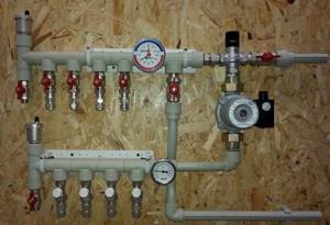
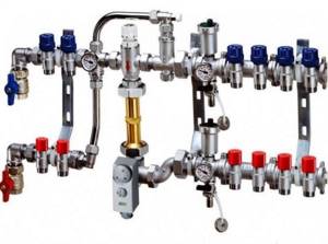
Assembling the factory manifold
To save on the price of heating equipment and make a collector unit yourself, you need to understand what factory-made products are made of. The kit includes the following parts:
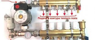
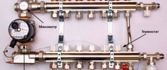
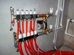
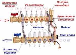
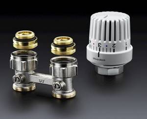
- A distribution element for connecting a supply line to 2 or more outlets, equipped with Eurocones (fittings for connecting pipes). In most cases, it is equipped with transparent flasks, where the coolant flow in each circuit is visible (rotameters).
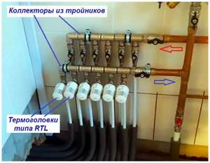
- The same for connecting to the return line. Instead of flow meters, there are thermostatic valves controlled manually from servo drives or thermal heads of the RTL type. Their operating principle is simple: when you press the spring-loaded rod, the flow area narrows, and the flow of water through the element decreases.
- Automatic air vents installed separately on the supply and return manifolds.
- Taps with plugs for emptying and filling circuits with coolant.
- Thermometers that record the total supply and return temperatures.
- Shut-off ball valves and mounting brackets.
Construction of a collector group for heated floors
For reference. On sale there are manifold units with rotameters on the return line, thermostat valves that regulate the flow. Changing the layout does not affect the operation of the heating circuits.
When purchasing a comb, you can change the complete set depending on your budget and connection diagram to the boiler. For example, buy a distributor without rotameters, install 1 thermometer instead of two, or place the unit in a control cabinet.
Factory kits are manufactured in such a way that the manifold for heated floors can be easily and quickly assembled with your own hands. Judge for yourself: the distribution elements are already assembled, you just need to connect them to the heating circuits and install the auxiliary parts according to the diagram. How to do this correctly, see the following video:
In addition to brass and steel products, there are varieties of combs made from plastic sections, as shown in the photo. Their installation is carried out in the same way, except with more caution when tightening. Please note that the main threaded connections on the groups for draining water and connecting pipes do not need to be packed with flax or FUM tape; rubber seals are provided almost everywhere.
Plastic distributors with installation kit
Designing a homemade collector
The first stage of work on creating a homemade distribution manifold is its design. A well-designed project will significantly simplify the work and allow you to create a high-quality welded heating manifold that is optimally suited for specific operating conditions.
Before assembling a heating collector, you need to evaluate a number of parameters of the building’s heating network:
- The number of heating circuits to which coolant must be supplied;
- Number and parameters of heating equipment (power, heating temperature, pressure, etc.);
- The need and possibility of further integration of additional elements into the heating system;
- Number of additional system elements (pumps, valves, shut-off valves, etc.).
Next, you need to carefully consider the features of connecting different circuits to the distribution manifold:
- Electric and gas heating boilers can be connected to the collector from above or below;
- If there is a circulation pump in the heating system circuit, boilers can only be connected from the end of the collector;
- Indirect heating boilers and solid fuel boilers can be inserted into the manifold only from the end side;
- The supply of each heating circuit is connected to the manifold from above or below.
In order to accurately and clearly see how to correctly assemble a heating collector, it is worth drawing its design on paper or printing it out if the diagram was created on a computer. The presence of a clear image in accordance with the scale and the required number of elements makes it possible to check during work to prevent installation errors.
Installing a comb in the heating system
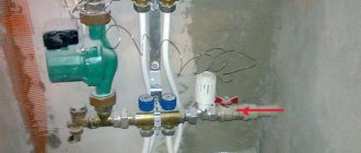
The primary task is to check the distribution manifold for tight connections. The installation is implemented according to the design scheme. Depending on the material used to manufacture the main unit, the connection conditions are determined.
In complex systems where there are many circuits for various purposes, it is necessary to install a vertical pipe - a hydraulic arrow. With its help, pressure equalization and distribution of forward and reverse flows of coolant are realized
The choice of connection technology depends entirely on the modification of the device used.
In addition to maintaining the level, during installation you must follow the following rules:
- electric and gas boilers are connected to the upper or lower pipes;
- a circulation pump is mounted at the end of the structure;
- the circuits can be connected at the top or bottom of the comb;
- indirect heating devices and boilers operating on solid fuel must be connected to the distribution group on the side;
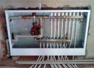
- the entire hydraulic separation unit for the underfloor heating system is placed in a protective box - this reduces the risk of damage to the constituent elements of the collector.
At the final stage, it is necessary to carry out a control start-up of the heating in order to timely identify hidden or obvious deficiencies in the design.
Additional information on organizing a radiant heating system using a distribution comb is provided in this article.
DIY comb assembly
The collector assembly technology includes the following steps:
- In accordance with the dimensions specified in the project, the required amount of materials is prepared;
- The pipes are connected to each other as specified in the project;
- All pipes must be connected to each other using a suitable tool;
- The pipe connections must be thoroughly cleaned and treated with sealant;
- A manifold assembled by yourself must be checked for leaks by closing all pipes except one and ensuring the supply of water to it - the absence of leaks in the closed pipes indicates that the device has been assembled correctly;
- The finished distribution manifold is painted and dried;
- After the paint has hardened, the device can be installed in the location chosen for it.
How to install?
Before installing a water distribution unit for cold and hot water supply, give an accurate answer to the following questions and consider the following points:
- How many water consumers are there on site? The number of collector outlets should be the same or slightly greater than the number of consumers. Excess branches are closed with plugs.
- What type of pipes will be used to install the water supply? It is necessary to purchase devices designed specifically for pipes made of the selected material.
- Estimate in advance the position of all engineering elements in the space of the plumbing cabinet (you can make markings on the wall). Please note that a water meter and a water filter are installed in front of the distribution comb. The convenient location of all devices facilitates maintenance and repair work.
- Get reliable fastening - a poorly secured distribution unit can lead to depressurization of connections and damage to the pipeline.
- Before installation, make sure that you have all the necessary consumables on hand: sealing material, gaskets, adapters.
Installation of the water distribution unit occurs in the following sequence:
- Install the inlet shut-off valves on the water supply riser.
- Install the meter, filter and check valve.
- Connect the manifold and securely fix it to the wall
- Install a water supply to each consumer. Secure the pipes with fasteners.
This operating algorithm will allow you to avoid errors. Regardless of whether the collector is needed for water supply or heating, its installation is the same. Such wiring requires more time, skill and money, but pays off quickly and provides comfort in further use. Collectors are appropriate not only in cottages and large houses, but also in apartments.
Will direct the coolant in the right direction! Do-it-yourself heating collector: how to make a device
The heating system of a modern private house is a complex structure consisting of several sections that operate separately from each other.
Different circuits can be used here : the main heating line with radiators, divided into several floors, heated floors, heating of office premises, etc. Therefore, the system cannot do without such a device as a collector.
With its help, the coolant is distributed along the circuits, taking into account the required quantity and required temperature.
Today, collectors are sold ready-made, taking into account the number of circuits and the required diameters of pipes connected to it. Making it yourself is also not difficult; in fact, it is just a pipe to which branch pipes are connected.
Main characteristics of the collector system
The main difference between the collector and standard linear method of redistribution of the coolant is the division of flows into several channels independent of each other. Various modifications of collector installations can be used, differing in configuration and size range.
The collector heating circuit is often called radiant. This is due to the design features of the comb. When examining the device from the top point, you will notice that the pipelines extending from it resemble an image of sun rays
The design of the welded manifold is quite simple. The required number of pipes is connected to the comb, which is a round or square pipe, which, in turn, are connected to individual lines of the heating circuit. The collector installation itself is interfaced with the main pipeline.
Shut-off valves are also installed, through which the volume and temperature of the heated liquid in each of the circuits is regulated.
A manifold group, complete with all the necessary parts, can be purchased ready-made or assembled independently, which will significantly reduce the cost estimate when designing heating
The positive aspects of operating a heating system based on a distribution manifold are the following:
- The centralized distribution of the hydraulic circuit and temperature indicators occurs evenly. The simplest model of a two- or four-circuit ring comb can balance the indicators quite effectively.
- Regulation of operating modes of the heating main . The process is reproduced due to the presence of special mechanisms - flow meters, mixing unit, shut-off and control valves and thermostats. However, their installation requires correct calculations.
- Ease of maintenance . The need for preventive or repair measures does not require shutting down the entire heating network. Due to the sliding pipeline fittings mounted on each individual circuit, you can easily shut off the coolant flow in the required area.
However, there are also disadvantages to such a system. First of all, pipe consumption increases. Compensation for hydraulic losses is carried out by installing a circulation pump. It must be installed on all collector groups. In addition, this solution is only relevant in closed-type heating systems.
Calculation of the circuits of the heating system of the house and their distribution
Before proceeding to the manufacture of the collector, it is necessary to accurately calculate it, taking into account the number of circuits and diameters of the pipes connected to it.
- We need to count the contours . Usually a separate area is allocated to each floor. If heated floors are used in some rooms, then one channel is output for each room.
- The distance on the collector between the return and supply circuits should be 25-30 cm , between the outlets 10-15 cm. That is, the device must be made so that it is easy to maintain and easily control the process of lowering or increasing the temperature in each section.
The main parameter of the collector assembly is the hydraulic balance of the structure and the heating system as a whole. It is based on the ratio of the diameter of the pipe used to make the collector and the circuit pipes. The sum of the latter should be equal to the diameter of the collector pipe. For example, if a home uses three separate sections where the supply pipes are ½ inch in diameter, then the pipe in the manifold will be 1 ½ inch in diameter.
Types of collectors
The design of the collectors is simple, so it makes sense to differentiate only by the material from which the combs are made and by the method of attaching the pipes. Structurally, they are divided into two groups:
- Distribution manifold. Designed to distribute liquid from a common channel to end consumers, distributing water into separate channels.
- Collection (return) manifold. Designed to receive liquid from several channels and send it to a common channel of the system.
Conventionally, collectors are divided according to the number of branches, the presence of shut-off valves, and the sizes of inlet and outlet openings.
These factors will have to be taken into account when choosing. A large number of circuits may require several collectors.
Mounting types
According to the type of fastening of elements, they are distinguished:
- With solder fittings. This method is often used for polypropylene pipes, less often for cross-linked polyethylene.
- Euroconus. Suitable for all types of pipes and manifolds.
- Combined. For example, the inlet hole is threaded, and the outlet holes are made for soldering with polypropylene pipes.
Types of collectors and ease of installation
The most convenient to install combs are made of cross-linked polyethylene. The collector material that is slightly less easy to install is polypropylene.
Installation of a polypropylene manifold and pipes can be done using fittings or welding - this is an effective and reliable method of creating joints, but makes it difficult to change certain sections of the structure. If the pipe is directly welded to the comb, then in the event of a leak at the junction with the manifold, the entire structure will need to be replaced, so it is better to use fittings to connect to the comb.
We recommend that you read: Polypropylene pipes and their sizes: how parameters affect the operation of the system
The tensile strength of polypropylene is high both in elongation and bending. When heated, you can deform the material and make bends, but you need to be careful here. When heated, the strength of the material decreases, which increases the likelihood of damage.
Materials for production
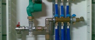
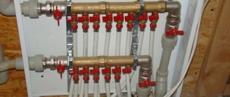
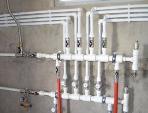
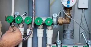
To make a collector unit, you can use pipes: metal (round and rectangular) or polypropylene. The connection of the outlet circuits to the collector pipe is made through ball or valve valves, with the help of which the supply of coolant to each section of the heating system is regulated.
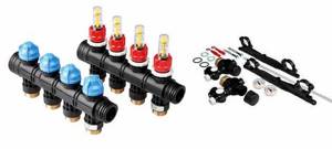
Polypropylene knot
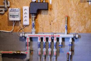
For this, pieces of polypropylene pipe are used, for example, with a diameter of 32 mm (you can use leftovers from the construction of a heating system at home) and several fittings in the form of tees with dimensions 32/32/32 - it is installed at the end of the collector unit, and 32/32/16 - intermediate elements for connecting to outlet channels in sections.
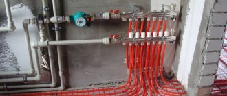
Photo 1. A manifold for a heating system made of polypropylene. The red lines indicate the coolant flow.
The first tee is mounted perpendicular to the main pipe. Its two outer pipes, located vertically, are connected as follows: the air vent is connected to the upper one, and the drain valve is connected to the lower one. A valve or ball valve is mounted to the opposite end of the collector installation. A pipe will go from it towards the boiler.
The intermediate tees are connected into one structure, which will be called a manifold. Therefore, the manifold installation is first assembled by welding tees 32/32/16 32 mm pipes , after which a tee 32/32/32 and a tap are installed on the opposite side. 16 mm pipes are connected to the intermediate fittings . It is with their help that the coolant supply to each circuit will be adjusted.
Advantages of a polypropylene device
First of all, it is necessary to note the low cost of the design, because for this you only have to purchase a small number of tees and taps. Other advantages:
- if the welding is carried out correctly, then such a structure will not leak;
- polypropylene is not subject to corrosion, does not rot and does not change its characteristics under the influence of water and high temperatures;
- light weight of the device;
- ease of installation.
From brass fittings
To assemble such an installation, fittings and valves made of brass are used .
To do this, you need to connect the same tees with double-sided couplings using a threaded connection with mandatory winding of a sealing material on the threads.
Moreover, if the threads on the tees are internal (which is most often the case), then the couplings must have external threads and tightening nuts.
The number of tees is the number of circuits, plus one. The latter is installed at the end of the manifold and is connected by two pipes to a drain valve and an air vent.
From a profile pipe
This is the most difficult process associated with metal welding. This requires skills and experience, because welding two pipes requires complete welding of the joint throughout the entire thickness of the products being connected.
Manifold manufacturing
Materials
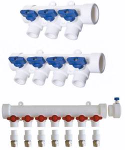
So, in order to independently assemble a polypropylene manifold with shut-off valves, you will need the following materials:
| Polypropylene pipes | 32 mm |
| Pipe plug | One |
| Couplings | For pipes with a diameter of 32 mm |
| Tees | Same diameters |
| Ball valves | They must also have the appropriate diameter, the number of taps must correspond to the number of bends |
Note! Ball valves can only be used to open and close a flow. If it is necessary to regulate its intensity, then a different type of shut-off valve should be used.
The diameters of pipes and fittings may have other parameters. The main thing is that they match the diameter of the pipeline.
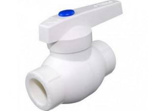
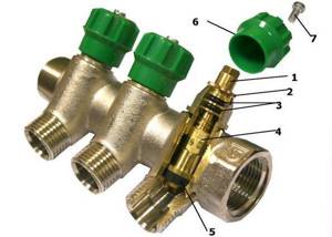
Ball valve made of polypropylene
Assembly
The instructions for assembling the comb are quite simple, the main thing is to follow this sequence:
- First of all, tees are connected to each other . Each tee serves as a tap.
- Then a plug is installed on one side of the device, and a 90-degree corner fitting is installed on the other (if the water supply will be from below).
- After the manifold without taps is assembled, you only need to install shut-off valves on each outlet . To do this, a small piece of tube is welded to each tee, to which a polypropylene ball valve is soldered.
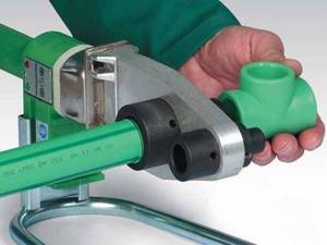
In the photo - soldering of polypropylene parts. To connect all the parts together, you will need a special welding machine (soldering iron). Below is the sequence of connecting fittings using this device:
- First of all, you need to warm up the soldering iron to operating temperature. A green LED will indicate that the instrument is ready.
- Since the fittings are connected to each other by sections of pipe, while the welding machine is heating up, you need to clean the section of the pipe that will be welded to the fitting. This is done using a special tool, which is placed on the tip of the pipe and rotated.
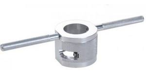
Pipe stripping
- After the soldering iron reaches operating temperature, you need to insert the fitting and pipe into the tool attachments and wait until the surface of the plastic melts. The soldering iron comes with a table that shows the melting time for parts of different diameters.
- After the time specified in the table has elapsed, it is necessary to remove the parts to be connected from the nozzles and join them together. They need to be held in this position until they harden, being careful not to move or turn them.
- After this, the tube connected to the fitting must be cut off, leaving the tip, for welding another fitting to it.
Advice! To get better at it, you should practice on pipe scraps and couplings, since an incorrectly soldered part can ruin the entire manifold.
According to this principle, all parts are connected to each other. If a manifold with ball valves is used for a heating system, then you need to make another similar device for the return.
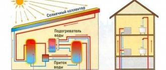
The vacuum type belongs to classic solar systems and operates on the principle of a conventional water heater. There are two types of devices that differ in the organization of heating and storage of coolant:
How to make a solar collector with your own hands
This device can be used to additionally heat water . Install it outside on the sunny side so that the sun's rays illuminate the device all the time.
- To make it, you need several boards from which the box is made.
- The back wall can be covered with any sheet material: plywood, metal, OSB, fiberboard or chipboard.
- is placed inside as insulation.
- Foil is attached on top of the polystyrene . It will act as a reflector of solar rays, increasing the intensity of their impact on the collector installation.
Attention! You can use any metal pipe as a collector for example, a copper pipe from a refrigerator condenser. It is formed in the form of a coil and laid on top of the foil. The ends of the tube are brought outside the wooden box: one is connected to the water supply network, the second is introduced into the house as a hot water circuit.
All that remains is to cover the entire structure with transparent glass . Install the device at an angle so that the sun's rays fall perpendicularly onto the collector group.
Rules for connecting fittings
Several options for assembling a manifold for a heating system were considered, but only two of them use fittings.
- The propylene manifold is assembled by welding plastic , for which a special device is used. The main task is not to overheat the material. Insert pipe sections into the tees along the axis of the connection. Rotating parts relative to each other is prohibited.
- As for brass fittings, the main requirement for assembly is to prevent coolant leaks at the joints. To do this, you can use various sealing materials, for example, flax tow, FUM tape or liquid fixative.
How to save money on a mixing unit
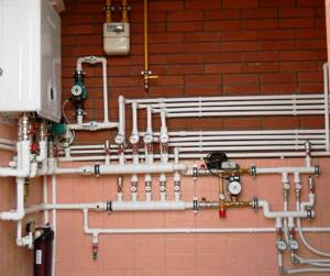
Many master plumbers consider it an integral part of the underfloor heating manifold, although these are 2 different elements that perform separate functions. The task of the comb is to distribute the coolant along the circuits, and the mixing unit is to limit its temperature to 35-45 °C, maximum 55 °C. The collector connection diagram shown below works according to the following algorithm:
- While the system is warming up, the two-way valve on the supply side is completely open and allows maximum water through.
- When the temperature rises to the calculated value (usually 45 °C), the remote sensor acts on the thermal head, and it begins to block the flow through the valve, pressing on the rod.
- After the valve mechanism is completely closed, the coolant, stimulated to move by the pump, circulates only in a closed floor heating network.
- The gradual cooling of the water is detected by a temperature sensor, causing the thermal head to release the rod, the valve opens and a portion of hot water enters the system, while some of the cold water goes back. The heating cycle repeats.
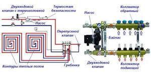
Note. If the manifold thermostats are controlled by servos, a bypass and bypass valve is added to the mixing assembly. The goal is to organize circulation in a small circle when the servos, for some reason, suddenly block all the circuits.
Good news for those who are very limited in funds, but want to heat themselves with warm floors: installing a two- or three-way valve with a pump is not always necessary. There are two ways to reduce the cost of the system by avoiding the purchase of a mixer:
- power the heating circuits directly from the gas boiler through the manifold;
- install RTL thermal heads on the manifold valves.
The manifold assembly, assembled from brass tees, provides for regulation by automatically limiting the reverse flow with RTL heads.
Let us immediately note that the first option contradicts all the canons and cannot be considered correct, although it is used quite successfully. The bottom line is this: high-tech wall-mounted gas boilers can maintain the temperature of the supplied water at 40-50 °C, which is acceptable for heated floors. But there are 3 negative points:
- In spring and autumn, when there is minimal frost outside, the boiler will not be able to lower the coolant temperature below 35 ° C, causing the rooms to become stuffy and hot due to heating of the entire floor surface.
- In the minimum combustion mode, the parts of the heating unit are covered with soot twice as quickly.
- Due to the same mode, the efficiency of the heat generator is reduced by 5-10%.
Advice. To avoid discomfort from the heat during transitional periods, you need to install traditional heating radiators in the rooms of a private house, and connect underfloor heating when it gets very cold.
Thermostatic heads of the RTL type operate on the principle of a two-way valve, only they are located on each circuit and are not equipped with remote sensors. A thermoelement that responds to changes in water temperature is located inside the head and blocks the flow along the circuit when it has heated up above 45-55 ° C (depending on the adjustment). In this case, the comb is connected directly to a heat source running on any type of fuel - wood, diesel or pellets.
Important condition. For normal operation of heated floors controlled by RTL thermal heads, the length of each circuit should not exceed 60 m. More details about the design of such heating and the correct collector assembly diagrams are described in a separate instruction and in the next video:
Options for homemade manifolds
easiest ways to assemble a manifold for a heating system with your own hands : from propylene pipes and brass fittings .
But the second one is simpler , because apart from two adjustable wrenches, nothing is needed here.
As for propylene, a welding machine is required to connect the parts of the device.
It is not difficult to work with, but there is a possibility that the first few joints will be connected poorly. Therefore, the advice is to make several connections on pieces of waste pipes and damaged fittings.
Reservoir classification
Switchgears differ in the material of the housing and parts and methods of fastening
This is important to consider when selecting, because... not all products are suitable for plastic pipes
The following types of collectors exist:
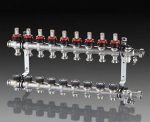
- Steel (made of stainless steel). Resistant to fire and high temperatures. The products are distinguished by their neat appearance and light weight; the collector is easily mounted on the wall.
- Brass (sometimes nickel-plated). They have a high cost, but are durable. Do not rust or deteriorate from high temperatures.
- Polypropylene. They are lightweight and resistant to corrosion.
According to the method of fixation, devices are classified as follows:
- with eurocone;
- threaded;
- with compression fittings that allow you to firmly connect plastic or metal-plastic pipes;
- with fittings for plastic pipes for soldering;
- combined.
The collectors are also available in 2 color options for installation on hot and cold water. Devices are divided by the number of outlets.
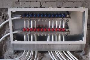
How to make a heating manifold with your own hands from polypropylene
Energy-efficient operation of heat supply systems is impossible without including a heating collector in the circuit, which is responsible for the proportional contour distribution of heat flows and the return of cold coolant to the boiler using a circulation pump. This made it possible to replace the linear circuit of powering consumers with an autonomous one, which increases the operational and repair readiness of the network.
Manifold cabinet for underfloor heating: distribution, vacuum, with hydraulic arrow
Energy-efficient operation of heat supply systems is impossible without including a heating collector in the circuit, which is responsible for the proportional contour distribution of heat flows and the return of cold coolant to the boiler using a circulation pump. This made it possible to replace the linear circuit of powering consumers with an autonomous one, which increases the operational and repair readiness of the network.
What is a heating collector
The device is structurally made in the form of a metal comb, equipped with several “input-output” points, which autonomously connect heating batteries to the in-house coolant.
The purpose of this connection is to adjust and control heating parameters:
- volume of network water;
- network temperatures;
- pressure in the supply and return networks.
The design of the heating unit controls heat transfer and ensures sanitary and hygienic living standards in the premises.
Important! To install heating in two-story buildings, the unit is mounted on each floor, thus implementing a high-quality heat supply scheme with floor-by-floor regulation.
Operating principle of the heating manifold
The distributor has a simple operating principle, which consists of several stages:
- Water, heated in the boiler unit to operating temperature, enters the supply part of the manifold, where the speed of the medium slows down due to the increased diameter of the comb, so the liquid flows evenly through all branches, with the same pressure at the branch points, supported by valves or shut-off and control valves.
- Each node is connected to a supply pipe circuit, creating equal heating opportunities for the radiators in the system, which is especially important at low outside temperatures.
- The coolant through the batteries gives off heat to the internal air in the room and, when cooled, enters a separate lower part of the heating manifold, where it is collected from the return circuits.
- The circulation pump directs the cooled liquid into the boiler for the next heating-cooling cycle.
Note! The number of outlet pipes in a group of collectors varies, and the device can also be equipped with additional branches.
Main types of heating collectors
Combs differ from each other in three respects:
- placement location - wall-mounted or floor-mounted;
- number of heating circuits;
- control elements: valves, valves, pumps, sensors.
The Russian market presents various types of nodes:
- for water coolant of a multi-storey building;
- distribution boiler system;
- for solar systems;
- for 2/3/4 contour units;
- vacuum geocollector;
- knot with hydraulic arrow.
Distribution radiator type is used for conventional radiators. It is made of 2 interconnected parts for supply and return. Connection diagrams for the distribution manifold for heating depend on the design features of the heated objects. There are wiring diagrams:
- top type;
- bottom type;
- side;
- diagonal.
The lower one is the most popular, since with such a harness the system is hidden under the floor, so it does not interfere with users.
Note! In addition, calculations show the high energy efficiency of such a connection due to reduced losses.
An example of a manifold connection scheme is a water heated floor, where the distribution unit uniformly supplies the coolant to all network rings. Such heating systems are equipped with a circulation pump; the number of groups is selected from the ratio - 1 point per 120 m of pipeline.
The vacuum type belongs to classic solar systems and operates on the principle of a conventional water heater. There are two types of devices that differ in the organization of heating and storage of coolant:
- “Wet tube” - a tank for collecting hot water is combined with a comb.
- U-type - the container does not have a direct connection to the distribution unit, so it is not limited by size.
Operating principle of the vacuum device:
- Under the influence of direct sunlight, the process of thermal absorption and heat transfer to the copper core occurs.
- The water, heating up, rises to the top of the device.
- The hot coolant, having transferred its energy to the external circuit, cools and returns to the copper tube.
A collector heating system with a hydraulic arrow is used in the design of residential buildings with a large heated area on several levels.
It is made in the form of a vertical hollow pipe, with elliptical-shaped plugs to equalize the coolant pressure.
This design solves several problems simultaneously, the main one of which is the stabilization of sudden temperature changes in pipes, which increases the service life of the system.
Note! Optimal heating operation with a hydraulic arrow is ensured if each circuit is equipped with an independent circulation pump.
Solar type for solar systems using the greenhouse effect. Water circulation occurs due to convection. To absorb sunlight, a distributor is installed in the circuit.
To accumulate heat, it is made in the form of a flat box treated with black adsorbent coating.
Heat energy is transferred to the network fluid circulating through the pipes, which is used as water or antifreeze.
The water collector has a very wide application, both in cold and hot water supply systems, and for heating apartments. The upper part of the unit for the water supply network is equipped with flow meters that balance the heating circuits.
The lower one for the return line is equipped with valve taps that perform additional fine-tuning of the system used during repair work. For 4-circuit systems, the device is equipped with a mixing unit, adjusting ball valves, a Mayevsky valve and a drain valve.
2/3/4 circuit units are most popular for connecting 2, 3 and 4 heating circuits, which is sufficient for small private houses.
Collectors characteristics:
- Brass distribution device with internal thread.
- Areas of application: hot water supply, heating using underfloor heating, connecting pump groups.
- Permissible temperature is 120.0 C.
- Working pressure - 25.0 bar.
Overview of the main manufacturers of heating collectors
Rehau, a leader in the heat supply systems market, produces combs for underfloor heating systems made from Ms 63 brass:
- HKV, for 2-12 circuits.
- HKV-D, similar to HKV, additionally equipped with flow meters and taps on the supply pipeline, and a control valve on the return line.
The Rehau heating collector is designed for a maximum operating temperature of 80 C and a medium pressure of 6 bar. What distinguishes it from other brands is that it is equipped with soundproof galvanized brackets.
Oventrop sells on the market a comb for underfloor heating, made of tool steel, maximum environmental parameters: pressure - 6 bar, temperature - 70 C. Air vents are located on it, the connection of pipelines to the batteries is made with a G3/4 thread, both right and and left connection.
The Valtec company produces manifolds for heating radiators and floor-mounted versions. The supply part of the distribution unit is equipped with a flow meter and an end tube with a float device for releasing air from the network with a shut-off valve and a drain valve.
Coolant parameters:
- supply temperature - 90 C;
- maximum pressure - 8 bar;
- line filling speed is 2.5 m3/h.
Millennium collector groups are made of stainless steel and equipped with thermostatic valves to regulate the heating process. Collector heating coolant parameters:
- Pressure - 10 bar.
- Maximum temperature - 100 C.
- The presence of integrated valves determines a wide range of applications for devices: with mixing units, electrothermal actuators and sensors.
Note! It is noteworthy that the design allows air vents to be installed on any side of the manifold.
DIY installation of a heating manifold made of polypropylene
Before creating a switchgear, a design calculation is carried out that corresponds to the design conditions and helps to choose the right equipment and materials.
To install a polypropylene heated floor collector with your own hands, use reinforced polypropylene components, possibly fiberglass, which does not undergo delamination.
Necessary materials:
- pipes of the required size;
- one plug for each group;
- couplings and tees according to the diagram;
- ball valves by number of circuits;
- soldering iron for plastic.
Sequencing:
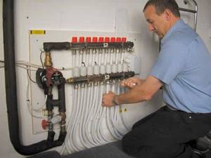
- The location for the block is chosen according to the project. They make a manifold cabinet for heating in the form of a special niche or purchase a ready-made housing from a retail chain and attach it to the wall.
- Use a soldering iron to complete the workpiece according to the drawing.
- Place the parts in the nozzles, after maintaining the soldering mode, connect the pipe and the coupling, allow it to cool, otherwise the joint will delaminate.
- The tees are connected first.
- When feeding from below, a plug is attached on one side and a corner on the other.
- The sections are welded on the bends, then valves and other devices are installed on them according to the diagram.
- Perform water pressure testing of the system with a pressure of 1.5 times the operating pressure and check the integrity of the seams.
- After eliminating leaks, connect the unit to the direct and return coolant.
User reviews about heating collectors
Many users who have experienced the work of debt collectors are happy to share their reviews on the Internet.
Victor, Nizhny Novgorod: “Rehau - the system meets European requirements, the only “but” is that you need to take a responsible approach to choosing the size and installing the comb.”
Andrey, Magnitogorsk: “Millennium is a good, high-strength, reliable steel structure, easy to set up in automatic mode.”
Leonid, Perm: “Italian Valtec comb, assembly place China, the price is much lower than that of Rehau, the polypropylene model is especially trustworthy - scale does not form on the walls and a decent warranty period of 7 years. Disadvantage: if the permitted pressure is exceeded, the taps may burst.”
Note! A good heating system collector is one of the most expensive elements of an individual heating supply scheme, so more and more buyers are installing a device for their home system.
In this case, the efficiency and safety of the system increases significantly, in addition, it allows you to fully automate the operation of in-house heating, maintaining the required sanitary conditions in the room, practically without human intervention.
Source: https://www.tproekt.com/kak-sdelat-kollektor-dlya-otopleniya-svoimi-rukami-iz-polipropilena/
What is a heating collector
The device is structurally made in the form of a metal comb, equipped with several “input-output” points, which autonomously connect heating batteries to the in-house coolant.
The purpose of this connection is to adjust and control heating parameters:
- volume of network water;
- network temperatures;
- pressure in the supply and return networks.
The design of the heating unit controls heat transfer and ensures sanitary and hygienic living standards in the premises.
Important! To install heating in two-story buildings, the unit is mounted on each floor, thus implementing a high-quality heat supply scheme with floor-by-floor regulation.
Subtleties of self-assembly
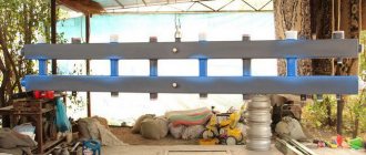
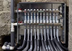
Before manufacturing the collector, it is necessary to draw up a diagram showing the location of all the elements of the assembly. It is better to choose steel pipes with a square cross-section as the manufacturing material. This type is easy to process, which significantly reduces labor costs for installing pipes.
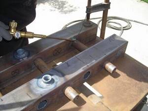
Manifolds made of profile pipes are used in the heating circuit of objects with a large number of circuits and a hydraulic separator. Square pipe parameters – 80*80 or 100*100 mm
The step-by-step process for producing a prefabricated distribution structure is as follows:
- Marking and cutting of the main body . According to the design diagram, it is necessary to mark the profile pipe. Using a gas cutter, holes are made in the marked areas.
- Preparing connections . The pipes are threaded using a die.
- Staffing . Next, the prepared pipe sections are welded to the body. Their fixation must be done by tack spot welding. Then, during the main welding, the workpieces are welded along the edges.
- Fastening elements . Brackets for fastening are welded to the block.
- Cleaning and finishing . After cleaning, the body is primed and coated with heat-resistant paint for metal products. The supply and return circuits are painted in two different colors for ease of identification.
If polypropylene pipes are used for production, you should pay attention to the presence of a reinforcing layer in them. In its absence, the plastic structure may be subject to deformation due to the current temperature conditions.
For those who do not have special tools, you can assemble a comb from separate ready-made elements. It is better to select components from one company.
Operating principle of the heating manifold
The distributor has a simple operating principle, which consists of several stages:
- Water, heated in the boiler unit to operating temperature, enters the supply part of the manifold, where the speed of the medium slows down due to the increased diameter of the comb, so the liquid flows evenly through all branches, with the same pressure at the branch points, supported by valves or shut-off and control valves.
- Each node is connected to a supply pipe circuit, creating equal heating opportunities for the radiators in the system, which is especially important at low outside temperatures.
- The coolant through the batteries gives off heat to the internal air in the room and, when cooled, enters a separate lower part of the heating manifold, where it is collected from the return circuits.
- The circulation pump directs the cooled liquid into the boiler for the next heating-cooling cycle.
Note! The number of outlet pipes in a group of collectors varies, and the device can also be equipped with additional branches.
Modifications of collector units
Before you begin assembling the collector assembly, it is necessary to determine its functional load. The equipment can be installed in several sections of the heating main. Based on this, the necessary equipment, dimensions and level of automation of the work cycle are selected.
In fact, for the full operation of such a node, two devices are needed. Using a comb, the coolant is distributed along the contours of the central supply pipeline. The return collector channel is represented by a collection mechanism and the point of departure of the cooled liquid into the boiler.
The collector heating circuit is selected based on the calculation of the required functionality and installation location. The choice of material for making the device does not affect the number of significant mechanisms
Installation of a homemade distribution group may be required when installing water-heated floors or for preparing standard heating with radiators.
Distinctive features of both options are their sizes and components:
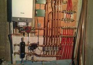
- Boiler room . The welded manifold group is made of pipes with a diameter of up to 100 mm. A circulation pump and shut-off valves are installed on the supply side. The return ring is equipped with shut-off ball valves.
- Warm floor system . Similar equipment is present in this mixing unit. With its help, it is possible to significantly save on coolant consumption, especially if additional flow meters are installed. Read more about the mixing unit in a heated floor system in this article.
Each of these solutions provides an individual installation scheme. Correct installation of all elements can be carried out only after detailed calculations of all operating point parameters.
The comb can be made of the same material as the pipeline. If it is different, adapters will be used to connect the collector
There are also differences in the required number of circulation pumps. In the boiler room, each line is equipped with this device. For heated floors, only one installation is provided.
Main types of heating collectors
Combs differ from each other in three respects:
- placement location - wall-mounted or floor-mounted;
- number of heating circuits;
- control elements: valves, valves, pumps, sensors.
The Russian market presents various types of nodes:
- for water coolant of a multi-storey building;
- distribution boiler system;
- for solar systems;
- for 2/3/4 contour units;
- vacuum geocollector;
- knot with hydraulic arrow.
Distribution radiator type is used for conventional radiators. It is made of 2 interconnected parts for supply and return. Connection diagrams for the distribution manifold for heating depend on the design features of the heated objects. There are wiring diagrams:
The lower one is the most popular, since with such a harness the system is hidden under the floor, so it does not interfere with users.
Note! In addition, calculations show the high energy efficiency of such a connection due to reduced losses.
An example of a manifold connection scheme is a water heated floor, where the distribution unit uniformly supplies the coolant to all network rings. Such heating systems are equipped with a circulation pump; the number of groups is selected from the ratio - 1 point per 120 m of pipeline.
Installation diagram
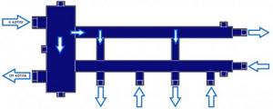
The distribution manifold consists of two parts. The first part receives heated process water coming from the boiler, and the second part receives the already cooled coolant, that is, the return flow.
- All parts that make up the comb are connected using high-temperature treatment with a special soldering iron for plastic pipes.
- An automatic air vent and a safety group are connected to one part of the collector.
- A tap is connected for emergency drainage of water.
- A tap and an air vent are placed on the second part of the manifold. Pipes will be connected here to return the cooled coolant.
- A circulation pump is connected to the return line, which creates pressure and the coolant begins to forcefully move through the pipes and heating circuits. It is mounted approximately to the boiler, that is, the arrow on the pump should be directed towards the boiler. This installation will allow the device to last much longer.
Advice.
To save fuel, it is better to install a three-way valve after the circular pump. The places that were intended for soldering the tee should be left on both combs and only after accurately determining where it will be located will it be possible to weld the plugs. The presence of a tee is necessary if in the future there is a need to expand the comb.
In order for process water to circulate in the system in the correct direction, it is necessary to install a so-called “reverse” valve.
Collector installation diagram
After completing the installation of the heating circuit, you need to connect both collectors to it and install the boiler in the location planned for it. Next, you need to screw one tap into both parts of the collector. The expansion tank is soldered on the supply side. The installation is completed by connecting the heating boiler to the collectors.
Advice. If the house in which the collector is installed has two floors, then it would be reasonable to connect four heating circuits to its terminals, respectively, two for each floor.
Warm floors create a special atmosphere in the house, and the installation of such a heating system should be taken very seriously. Before assembling it yourself, you need to carefully consider every little detail and review the various variations. If there is any error in the calculation, then further operation and maintenance of the system as a whole will become impossible and everything will have to start again.
DIY installation of a heating manifold made of polypropylene
Before creating a switchgear, a design calculation is carried out that corresponds to the design conditions and helps to choose the right equipment and materials.
To install a polypropylene heated floor collector with your own hands, use reinforced polypropylene components, possibly fiberglass, which does not undergo delamination.
- pipes of the required size;
- one plug for each group;
- couplings and tees according to the diagram;
- ball valves by number of circuits;
- soldering iron for plastic.
- The location for the block is chosen according to the project. They make a manifold cabinet for heating in the form of a special niche or purchase a ready-made housing from a retail chain and attach it to the wall.
- Use a soldering iron to complete the workpiece according to the drawing.
- Place the parts in the nozzles, after maintaining the soldering mode, connect the pipe and the coupling, allow it to cool, otherwise the joint will delaminate.
- The tees are connected first.
- When feeding from below, a plug is attached on one side and a corner on the other.
- The sections are welded on the bends, then valves and other devices are installed on them according to the diagram.
- Perform water pressure testing of the system with a pressure of 1.5 times the operating pressure and check the integrity of the seams.
- After eliminating leaks, connect the unit to the direct and return coolant.
Installation of distribution manifold
When installing the distribution manifold inside the wall, a recess is made into which the comb and inlet and outlet pipes are placed. If it is possible to install the comb in a utility room, then this is the most suitable place to install this device.
The distributor installation process is very simple and is carried out in the following sequence:
- supply from the riser is turned off.
- The supply pipe is connected to the central inlet of the collector.
- If the device is not equipped with taps , then a ball valve is connected to each output of the distributor.
- is connected to each tap .
- If the number of taps exceeds the number of water supply circuits , then the extra outlets should be closed with plugs.
- After connecting all the pipes , the collector is fixed to the plane of the wall or box with clamps.