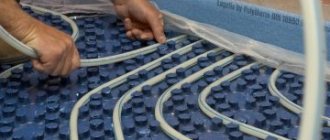
When choosing an energy source for a heated floor system, many homeowners prefer water heating due to its efficiency and reliability. Installing water heating as an additional or main heat source is not a complicated process.
The main component of the heating design is the comb for the heated floor, which is responsible for performing several basic functions.
Let's understand the functionality of the node and the specifics of its work.
Purpose of the device
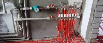
The design of a comb for heated floors is reminiscent of heat collectors, which are installed together with a hydraulic arrow. Place the comb in the place where the ends of the heating pipelines are collected after they are laid on the floor surface. Its direct purpose is:
- Providing the required amount of coolant for heated premises. This is achieved by regulating the supply using special valves.
- Reducing the water temperature to operating parameters, which should not exceed +45°C.
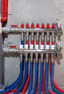
The main part of the collector consists of two parallel pipes for direct and reverse supply of coolant. There are nozzles located on them, to which the ends of the heating pipelines are connected. When installing a heated floor comb, two main collectors are connected to the corresponding pipelines of the heating system.
In this video you will learn about the types and main differences of the comb:
What is it needed for
When installing water pressure systems, there is a rule: the total diameter of all branches should not exceed the diameter of the supply pipe. In relation to heating equipment, this rule looks like this: if the diameter of the boiler outlet fitting is 1 inch, then the system allows two circuits with a pipe diameter of ½ inch. For a small house heated only with radiators, such a system will work effectively.
In fact, there are more heating circuits in a private house or cottage: heated floors, heating of several floors, utility rooms, and a garage. When they are connected through a tapping system, the pressure in each circuit will be insufficient to effectively heat the radiators, and the temperature in the house will not be comfortable.
Therefore, branched heating systems are made using collector systems; this technique allows you to adjust each circuit separately and set the desired temperature in each room. So, for a garage, plus 10-15ºС is enough, and for a nursery, a temperature of about plus 23-25ºС is required. In addition, heated floors should not heat up more than 35-37 degrees, otherwise it will be unpleasant to walk on them, and the floor covering may become deformed. With the help of a manifold and shut-off temperature, this problem can also be solved.
Video: using a collector system for heating a house.
Manifold groups for heating systems are sold ready-made, and they can have different configurations and the number of outlets. You can select a suitable collector assembly and install it yourself or with the help of specialists.
However, most industrial models are universal and do not always fit the needs of a particular home. Redesigning or modifying them can significantly increase costs. Therefore, in most cases it is easier to assemble it from separate blocks with your own hands, taking into account the characteristics of a particular heating system.
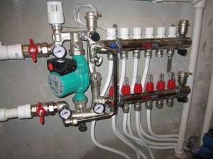
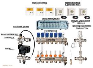
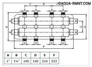
Manifold group for heating system assembly
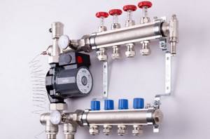
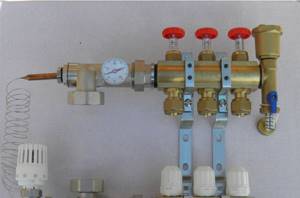
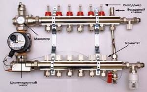
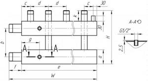
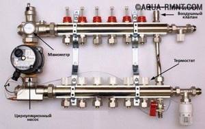
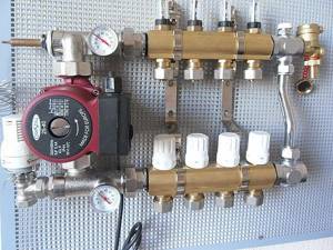
The design of the universal collector group is shown in the figure. It consists of two blocks for forward and reverse coolant flow, equipped with the required number of outlets. Flow meters are installed on the supply (direct) manifold, and thermal heads are located on the return manifold to regulate the return water temperature in each circuit. With their help, you can set the required coolant flow rate, which will determine the temperature in the heating radiators.
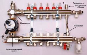
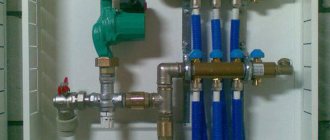
The manifold distribution unit is equipped with a pressure gauge, circulation pump and air valves. The supply and return manifolds are combined into one unit with brackets, which also serve to attach the unit to a wall or cabinet. The price of such a unit is from 15 to 20 thousand rubles, and if some of the bends are not used, its installation will be clearly impractical.
The rules for installing the finished block are shown in the video.
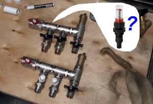
Comb - collector unit
The most expensive elements in a manifold distribution block are flow meters and thermal heads. To avoid overpaying for unnecessary elements, you can buy a collector unit, the so-called “comb”, and install the necessary control devices with your own hands only where necessary.
The comb consists of brass tubes with a diameter of 1 or ¾ inches with a certain number of taps with a diameter of ½ inch for heating pipes. They are also connected to each other by a bracket. The outlets on the return manifold are equipped with plugs that allow you to install thermal heads on all or part of the circuits.
Some models may be equipped with taps, with their help you can regulate the flow manually. Such combs have a cast body and are equipped with a fitting/nut thread at the ends, which allows you to quickly and easily assemble a manifold from the required number of branches.
In order to save money, the manifold for heating systems can be assembled from individual elements independently or completely made by hand.
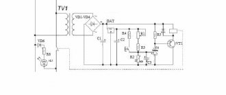
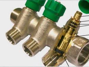
Two way valve design
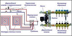
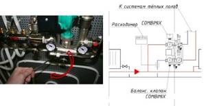
In the heated floor installation scheme, the valve is installed directly in front of the comb. It is connected to a temperature sensor, which is placed at the coolant return manifold. In addition, the distribution node diagram includes:
The two-way valve is controlled using a thermal head, which is directly connected to the temperature sensor. This valve has only two operating positions: open or closed.
At the beginning of the heating process, the device is in the open state, and the coolant enters the collector. The valve remains open until the water temperature reaches the operating value. As soon as this happens, the “sensor + thermal head” tandem will close it, and the coolant will stop flowing from the heating boiler.
During this period, the floor heating comb pump will independently circulate hot water through the heating circuits. In this case, the coolant will gradually cool down, and when its temperature drops below the operating temperature, the valve will open again.
Proper mixing of hot and chilled water occurs due to a balancing valve that regulates the volume of waste coolant.
Purpose of a comb for heated floors
A heated floor comb is not an independent unit, but a set of elements included in a manifold group. He is responsible for the operation of the heating floor.
More often, a warm water floor includes several circuits that have different lengths and require different amounts of coolant. Therefore, without a distribution unit, the device will not work properly.
Without a manifold, hot water will flow directly from the boiler into the floor pipes, most of it moving into the smallest loop. As a result, the small circuit will overheat, and the large circuit will not have enough heat.
If the coolant is supplied from central heating, then its heating degree is higher than required for a heated floor. If it goes into the circuits undiluted with cooled water, then overheating is guaranteed.
To do this, you need a mixing unit, where the liquid is mixed to the desired degree.
The device allows you to adjust the amount of coolant flow into each loop and the degree of its heating. This will help ensure the required temperature level.
Operating principle of a three-way regulator
A smoother process of heating the circuits occurs when the underfloor heating comb is connected through a three-way valve . In this case, the distribution unit has three connection points: from the boiler heater, the supply manifold, and the inlet of the cooled coolant.
In the initial position, the regulator is only open to supply hot water from the boiler. When its temperature exceeds the desired value, the regulator will partially open the underfloor heating system and slightly close the connection to the boiler.
Then the hot and cooled water will mix. The regulator will remain in this position until the temperature drops below the required value. When this happens, the valve will shut off the underfloor heating circuit and completely open the supply from the boiler.
This work cycle is repeated continuously. This heating method is usually used for large areas exceeding 150 m². But it is believed that the three-way regulator is less reliable and more likely to fail.
Comb selection criteria
The first thing you should pay attention to is what material this structure is made of. The most popular are brass manifolds , which are produced by casting. In this case, the result is a strong and durable part, but at the same time it is very expensive.
Welded products made of stainless steel are cheaper. The comb turns out to be quite durable, but this material can be subject to electrochemical corrosion.
Products made from high-quality plastic material are considered a budget option. Their qualities are not inferior to metal parts.
The next criterion for choosing a collector is the number of operational outlets. It is best to choose a product with outlets equal to the number of heated circuits, so that you do not have to plug extra holes.
Considering the performance of the selected comb, it is desirable that it has some reserve and can withstand a sharp increase in pressure in the heating system.
Next, the technical equipment of the collector is taken into account for automation and regulation of coolant temperature.
If you need a comb that will last you a long time, then brass is your option.
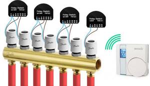
Today, there are combs that can be connected to thermostats and programmable controllers. With their help, it is much easier to make adjustments, as well as control the quantity and quality of coolant in the circuits.
Briefly about the main thing
The equipment of the collector block must meet the requirements for the functionality of the system. The collector device ensures uniform heating of the heating elements and a constant temperature in the room. Made from the following materials: polypropylene, brass and steel.
The manifold consists of a system to which threaded elements, fittings or control valves are connected. The collector is installed in a special cabinet or brackets are used.
Along with it, a mixing unit is used.
The durability of combs directly depends on the material and workmanship. You can purchase a ready-made distribution block or assemble it yourself from individual elements.
| Additionally The exhibition of houses “Low-Rise Country” expresses sincere gratitude to the specialists for their assistance in creating the material. – supplier of water supply and heat supply systems for any facilities, from the world's leading brands. The company also develops and installs automated metering systems for energy consumption. If you need more detailed advice, you can use the following contacts: |
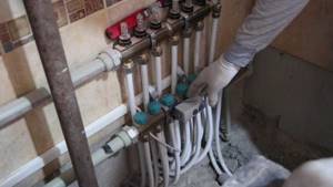
Product installation features
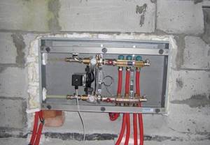
When installing this structure, it is necessary to take into account a number of rules and features . Typically the collector is installed on the wall, in the middle or closer to the floor. To do this, it is best to use a special manifold cabinet, which gives a more aesthetic appearance to the structural unit.
It must have holes drilled for suitable piping. The comb is attached in such a way that it is possible to bleed air from the heating circuits. This will allow you to carry out repairs without problems in the event of an accident.
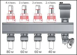
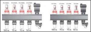
The length of the contours should be approximately the same to make adjustments easier. This is done based on two indicators: coolant flow and temperature. For this purpose, a flow meter and temperature sensors are built into the circuit.
An important condition when installing heated floors is that the total length of each circuit should not exceed 60 m. Otherwise, it will be difficult for the coolant to overcome the hydraulic resistance in the pipelines.
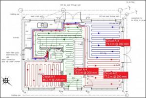
When creating a warm floor, each room has its own separate heating branch.
Comb for water heated floors: principle of operation
- normalize water temperature;
- distribute the liquid along the contours.
In heating boilers, the liquid is heated to 60 - 90 °C and disperses hot along the circuit.
For obvious reasons, it is impossible to pass such a hot coolant into a warm floor.
Lowering the temperature is one of the main tasks implemented in the collector unit. Temperature reduction can occur in two ways:
Mixing cooled coolant with hot fluid is the most popular method. Mixing occurs in a three-way valve. After the circulation pump drives the liquid through the circuit, it cools down. It is this cooled return that is added to the hot coolant. The proportions of both flows are checked by a thermal head. Its working part is installed on the valve itself, and the sensor is installed on the supply.
Instead of a thermal head there may be a servo drive. And for stable heating systems, when the boiler produces a relatively uniform temperature, you can set the three-way valve to one position, attach a thermometer to it and control the degrees manually.
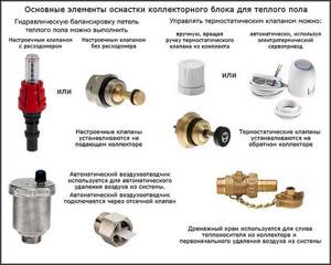
Main elements of the collector unit
Without a circulation pump, the water floor circuit will not work. Also, if you place the pump before the three-way valve, the coolant will not enter the floor coil, but will flow in a small circle where there is less resistance.
Temperature limitation is implemented by installing a special thermal head into the system, which measures the temperature of the coolant. Outwardly, it is similar to a radiator thermostat, but is fundamentally different from the latter, which measures the air temperature in the room.
A person sets a value that is comfortable for himself, and the device, detecting exceeding the threshold, limits the clearance inside the device, reducing the flow of coolant.
Warm floors made in Russia are in increasing demand. Warm floor national comfort - reviews and cost.
What you should pay attention to when choosing a manifold for a heated floor, we will tell you here.
Electric heated floors under tiles are installed in bathrooms in apartments, since it is prohibited to install water floors in the apartment. Read about the design features of this system and safety precautions at the link.
Manufacturing materials
The reliability and durability of the collector directly depends on the material from which it is made. A comb for heated floors can be metal or polymer. Each option has its own advantages and disadvantages.
Polypropylene
A manifold made of polypropylene pipe is an extremely economical option. In addition to the affordable price, one can note the light weight of the device. Models with fittings and combs with shut-off ball valves are available for sale. To connect metal products, combined fittings are used.
The disadvantages of polypropylene collectors include:
- thick walls, due to which the passage cross-section is smaller than that of metal combs of the same size;
- less strength and durability compared to metal models;
- oxygen permeability - even if polypropylene is reinforced with fiberglass reinforcement, there is diffusion of oxygen, which provokes corrosion of steel elements of the heating system and boiler.
Collector block made of polypropyleneSource chudopol.ru
The list of advantages of polymer combs includes:
- resistance to aggressive environments (antifreeze can be used as a coolant);
- resistance to electrochemical corrosion;
- low heat loss compared to metal products.
You can buy a polypropylene heating manifold or make it yourself from a pipe of a suitable size and fittings.
Brass
Brass is a classic material for the manufacture of heating manifolds. The comb is made using the stamping method or holes are drilled for bends and threads are cut on sections of a hollow brass rod.
Collectors made of this material have one drawback - zinc is washed out of the metal. Therefore, it is recommended to use nickel or chrome plated products. These combs:
- durable;
- resistant to corrosion and aggressive environments.
The disadvantage of brass manifolds is their high price. You can also note the smaller flow area compared to steel models.
Brass manifoldSource prom.st
Stainless steel
Stainless steel collectors are in demand due to the combination of high performance parameters and affordable prices. The advantages include:
- large flow area, making it easier to balance the underfloor heating system;
- mechanical strength even in the presence of a weld;
- resistance to corrosion and aggressive environments;
- durability.
A heating comb of a reputable brand (for example, VALTEC), made of high-quality stainless steel, is designed for 30-50 or more years of operation. Cheap products from unknown manufacturers, including counterfeits, are often made of low-quality steel and are susceptible to corrosion.
Stainless steel manifoldSource termo-snab.ru
What does the comb consist of?
Having decided on the adjustment method, having decided whether a three-way valve or thermal heads will be used, the remaining elements of the comb are assembled.
- The collector itself is two parallel tubes (supply and return) with outputs. One side of each comb is plugged. It can be purchased ready-made, but its cost is the main cost of the mixing unit (we are talking about thousands of rubles). It is much cheaper to assemble a comb from a series of tees, which have an internal thread on one side and an external thread on the other. The circuit tubes are connected to the side outlets (via fittings - crimp or solder).
- Manometer that controls pressure.
- Burst valve , which will operate if the pressure is exceeded.
- Servo drives for each circuit are especially important when the length of the circuits is different (if you give free rein to the laws of physics, the temperature in them will be significantly different). Thermostats equalize pressure and temperature.
Calculation
Calculating what heating temperature is required to heat a particular room can only be done experimentally, that is, the user must try several settings, analyzing the time to achieve a comfortable environment in the room and the temperature level there. Fortunately, this is much easier to do with a rotameter than fiddling with the supply valves and pump manually.
There are no fixed values for rooms; this nuance is due to the fact that many factors influence heat retention in a room: thermal insulation, area, length of the coil, and the like.
On combined models, you can make a preset (usually this is done) by the number of valve revolutions - each full turn reduces/increases the clearance by a fixed value. You can use the following method:
- First, the volume of coolant required for each circuit is calculated, its percentage relative to the total amount of liquid for the entire system.
- Based on the result obtained, the initial position of the valve (ring) is set for each section.
- The final adjustment of the flow meter is made during the operation of the system, based on the actual established temperature, according to feelings of comfort.
As we have already noted, for one or two rooms or rooms with identical parameters, a collector group with flow meters is desirable, but not as significant as for houses and apartments where several zones of different sizes are heated.
With equal coolant flow for the circuits of a large and small room, achieving the desired temperature in them will be different. The larger the area, the lower the quality of thermal insulation, the lower the level of heating will be. Accordingly, larger rooms will require a more intense and significant flow. And, conversely, in a smaller object you need to set the flow rate lower, otherwise it will be hot. But there is also a nuance here: if it has poor thermal insulation, then the values may become equal.
As you can see, the calculation is influenced by many factors; the comfortable mode even depends on the time of year. Adjustment is also called balancing, since the limited resource from the boiler is distributed; a change on one coil affects the others. Tuning can be done frequently, so the simplicity provided by flowmeters is highly sought after.
Let's give an example. Inside the house, an underfloor water heating system is installed for the bathroom and another room, for example, for the living room. Without a rotameter, a gas boiler will heat the liquid for the specified rooms equally, and one temperature regime will be established. It may be comfortable for the living room, but it will be hot in the bathroom.
For heating the first one requires more heated water from the boiler, for a small bathroom less. A water meter will allow you to quickly and comfortably bring the temperature of each room to the same level or set it to a different, but comfortable level, taking into account the characteristics of the room.
Also, when balancing, it is important to pay attention to the length of the circuit tubes, regardless of its configuration.
Let us note some more advantages of flow meters; the device will allow:
- it is easy to control the volume of liquid of a certain temperature sent for heating, which also entails the opportunity to more rationally manage the energy source (boilers). If it is of an electric type, then this nuance is very relevant;
- warm all branches evenly, avoid temperature fluctuations, which will increase comfort. On the other hand, it will allow you to turn off the heating where it is not needed, or reduce/increase it as desired by the user;
- You can visually monitor the volume of coolant flowing from the boiler through the main pipes. By looking at the flow meters, their bulbs with graduations and indicators, you can immediately determine visually the heating level of the room (you will also need to compare its dimensions and other parameters) and how much resource is being consumed.
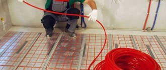
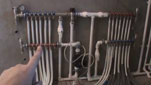
Installation
Let's consider the installation of one of the heating circuit circuits.
Starting from the heating boiler, the following is installed:
- Simple tee. One of its outputs is directed to the warm floor, the other to radiator heating.
- A manifold cabinet is installed. It is advisable to choose the installation location so that the cabinet is closest to the center of the house.
- Three-way valve (flow direction is checked according to the arrow).
- Circulation pump. It is installed at the outlet of the three-way so that the flow is sucked out of the valve.
- Supply and return combs (assembled from tees, or purchased) are mounted in the cabinet on mounting strips. The combs are connected by a bypass.
- A temperature sensor from a three-way valve is fixed not far from the pump. The place where it is located can be insulated with penofol or a similar heat insulator to take more accurate readings.
- At the highest point of the comb, an air vent valve (Maevsky valve) is installed.
- Thermostats for each branch are installed on the return comb.
- Floor pipes are installed, wiring and laying are done in the rooms. The connection is made to fittings using union nuts. There is no need to cut the length of the pipe from the coil until all the turns have been laid. Having brought the pipe to the manifold cabinet, it is cut to length and secured to the return comb.
- A regular tee connects the floor return to a three-way valve (to its side outlet, which mixes in cold coolant), the other part of the tee is the return of the entire system, which goes to the boiler.
- Heating connection - test run and adjustment of servo drives separately for each circuit.
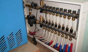
Servo driven comb
Only after making sure that there are no leaks can you fill the screed.
How to make a device yourself
Making a distribution unit yourself is not too troublesome and not at all expensive, so this option is increasingly being chosen by home craftsmen who want to save money on purchasing such an expensive device.
Drawing up a drawing
Before you begin assembling the comb with your own hands, you need to draw up a competent drawing or diagram of such a device, taking into account the number of circuits, load and other basic parameters.
A pre-compiled assembly diagram for the distribution unit allows all work to be done correctly, with the highest quality and speed.
Selection of the required material
To make a comb with your own hands, you will need to purchase a few of the simplest parts presented:
- ½ inch brass tee - four pieces;
- ball valve with a ½-inch threaded connection - five pieces;
- silicone sealant;
- standard ½" plug.
The purchased tees must have a configuration in which there is an internal thread on one side of the product, and an external thread on the opposite side.
Manufacturing
The sequence of self-manufacturing of a distribution comb for a “warm floor” heating system:
- Assemble the tees into a single line. To connect each subsequent tee to the previous one, external and internal threads are used, which allows you to get a straight pipe with side branches. Reliable sealing of all connections involves treating the threaded connections with silicone sealants applied to the external threads. All excess sealant must be removed using a rag.
- A standard tap is installed on the inlet part of the resulting straight pipe using silicone sealant and a threaded connection.
- A plug is installed on the opposite side of the base on a homemade comb.
- All side branches are provided with screw-in and sealable taps.
It is quite possible to make your own design for any number of taps
The homemade distribution comb obtained in this way is perfect for arranging a four-circuit “warm floor” system.
An equally popular option is to independently solder the comb using conventional polypropylene pipes and additional fittings. The number of tees is selected individually, and the sections of PPR pipes must have a diameter similar to them. With this option, cut pipes serve as connecting nipples for joining tees.
Tips for choosing
If you decide to buy a manifold for heated floors, you need to choose it according to the following criteria:
- For how many circuits is it intended? That is, how many separate branches of the heated floor are planned (the radiator branch does not count).
- Equipment. Even just buying all the parts separately and assembling them yourself will cost less. But with a ready-made, assembled comb there is a minimum of hassle.
- Material. Collectors are available in metal (steel, copper, brass) and plastic. Plastic ones can be used for simple systems with a short circuit (for example, for a toilet or kitchen).
- Adjustment. Even on factory models there are manual control valves (rather than servos).
Conclusion
A simple comb without servos is not very expensive.
Distributor made of metal fittings
If you use metal fittings instead of polypropylene, you will be able to slightly reduce the size of the structure and do without a soldering iron. But here another pitfall awaits you in the form of cheap thin-walled tees, which are scary to handle with a pipe wrench - low-quality material can crack. If you buy high-quality fittings, then the total price of the product will be closer to the factory manifold, although the savings will still remain.
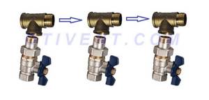
For manufacturing, you need to select internal/external thread tees made of good brass, shown in the photo, and ball valves with a low stem and a butterfly handle. The same radiator valves will go to the second part of the comb. The assembly technology is simple: pack the threads with flax or thread and twist the fittings together, and then install the taps and other parts.
Installing flow meters on a comb of brass fittings is a difficult issue. Then the supply line will have to be assembled from crosspieces and special adapters for rotameters will be installed. Some of them are also made for Eurocone, so the adapter will have to be machined. It is easier to balance the system without flow meters.
As you can see in the photo, there is nowhere to put the rotameter here
Video on the topic
Having allocated a considerable amount of funds to create a water heated floor (WF) system, the user sometimes does not receive the expected level of comfort or savings, which supporters of such heating vying with each other about. And if the calculation of communications was carried out correctly, and the installation was carried out without errors, then, most likely, the reason for the ineffectiveness of the thermal installation is in its incorrect functional settings. These primarily include adjusting the temperature of the warm water floor. At the same time, it is based on the concepts of the temperature of the coolant in the system and the surface of the floor covering, as well as the temperature regime in the rooms.
Let's look at how these concepts are linked together in practice, with different methods of TP management.
How to assemble a homemade comb
So, a homemade comb includes the following elements:
- Nourishers. These include a two-way or three-way valve that operate automatically.
- Temperature sensors.
- Circulation pump.
- Thermostat and other controls.
- Stopcock.
- Drain valve, air vents.
In order to assemble a homemade comb you will need the following tools and materials:
- Soldering iron.
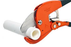
- Scissors for soldering pipes.
Optimal temperature parameters
The preferred temperature of the heated floor is selected according to individual needs. After all, some people like invigorating freshness in the house, while others want to bask in the warming energy flows. However, there are generally accepted standards for the preparation of coolant, heating of floor coverings and, accordingly, indoor air. They are determined by sanitary and technological requirements. These standards have already been mentioned here, however, let us briefly recall:
- The optimal floor surface temperature is 28 0 C;
- if the room is designed for a long stay of residents or there are other heating sources, then it is advisable to reduce the temperature to 22-26 0 C - this energy regime is optimal from a medical point of view. In addition, heating of the coatings is unnoticeable upon bodily contact with them, which does not cause tactile discomfort;
- for rooms where the heat supply is the only source of heating, and also where residents are present only periodically (bathroom, toilet, hallway, loggia, covered veranda), the surface temperature of the floor covering can be raised to 32 0 C.
Ways to control the temperature of a heated floor
To ensure the specified requirements of sanitary and technological standards, user preferences, the heated floor can be adjusted using the following adjustment methods:
- temperature of the coolant entering the TP system. The main control of the heat flow intensity is carried out by changing the settings of the heat generator (boiler). It is suitable only when supplying low-temperature coolant, when a separate boiler operates to compensate for heat loss from underfloor heating. This control method is the simplest, although ineffective, therefore it is rarely used in small private TP systems;
- collectors and mixing units. Such adjustment can be manual or automatic, carried out individually for each circuit or as a whole for the entire heating group - on a common comb through which several TP branches are supplied with coolant.
The starting points for changing system settings can be measurements of the coolant temperature in the supply or return distributors. Indeed, for water heating, unlike electric heating, it is not typical to install thermal sensors in the floor structure - they are mounted directly on the collectors. Most often, such sensors or sensitive elements are parts of thermostatic valves, through which the heated floor is adjusted.
Control signals to automatic devices can also come from air temperature sensors located in heated rooms.
Kinds
The design of different models of combined type measuring and adjusting float water meters is almost the same:
Types of water meters based on functionality for underfloor heating manifolds:
- measuring - a shut-off valve must be installed to it, the valve of which is turned by the user to adjust it, depending on the values shown by the water meter;
- regulating - only for coolant distribution;
- combined - two types are combined, with a built-in valve. Some models can perform automatic adjustment.
For underfloor heating, the first and second types of float rotameters are most often used.
Manual adjustment of TP collectors
The simplest, although time-consuming, setting method is to adjust the temperature of the heated floor using manual valves. The task is somewhat simplified by installing flow meters (rotameters) on the comb.
Flow meters simplify the dosage of the amount of circulating coolant (flow) in one separate circuit of the underfloor heating system. In the case of group temperature control throughout the collector, the rotameter can also be used to balance the flow of coolant (smoothing out the difference in hydraulic resistance) along loops of different lengths.
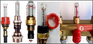
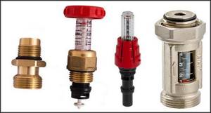
The main elements of a flow meter valve are:
- housing with shut-off and control valve. It is screwed into the corresponding technical hole of the manifold;
- a flask made of transparent plastic or glass with a printed scale;
- float indicator that allows you to visually control the flow of liquid through the rotameter.
Manual adjustment of the underfloor heating manifold is carried out by screwing/unscrewing manual valves or adjusting the throughput of flow meters.
Important! Improvement in the efficiency of the underfloor heating system, as a result of its manual adjustment, will be noticeable only in the case of intensive circulation of the coolant through it. This can only be achieved by using a separate heat pump.
The sequence of manually setting the temperature of a warm water floor
At the beginning of the adjustment operations, it is necessary to make sure that the pipelines of the TP system (secondary circuit) are completely filled with coolant and have no air pockets. They are filled following the main heating system (primary circuit). At this time, all shut-off and control valves on the collectors must be closed.
After opening the main valves for the supply and return of the distributors for heated floors, the shut-off devices on each of the loops are opened sequentially. Air is bled through Mayevsky valves or automatic comb air vents. It is recommended to fill the next branch only after the previous one has been completely filled and its air has been guaranteed.
Having completed filling the first loop, it is necessary to turn on the heat pump of the secondary heating circuit and circulate the coolant through its system. The efficiency of liquid circulation is checked with built-in or overhead thermometers. As a last resort, you can simply put your hands on the supply and return pipes at the same time - they should be warm, but with a slight difference in heating.
The filled first loop should be cut off from the collectors at both ends using local shut-off and control valves. Then, the above actions are carried out with the next loop.
After sequential filling of all heat pump circuits, their shut-off devices are opened and the heat pump is switched on to operating mode. The temperature of the warm water floor is adjusted through the supply of coolant to each of its branches. It is set by changing the liquid flow rate (with a valve or rotameter), and control is carried out by changing the temperature gradient between the supply and return flow. Ultimately, this difference for different circuits should be the same, within 5-15 0 C. The longer the loop, the more intense the coolant will cool and the greater its consumption is required.
Important! Heat exchange in underfloor water heating systems occurs with great inertia. The delay in heating the coating surface is especially noticeable if the pipes are laid in too thick a concrete pour (over 60-70 mm). Sometimes the effect of changing the coolant supply intensity becomes noticeable only after a few hours.
To monitor the correct adjustment of a warm water floor, it is rational to use non-contact laser or contact electric thermometers. Their installation to measure the temperature of the supply and return pipes will help reduce the time to obtain the result of changing settings from several hours to 10-15 minutes.
How to build a collector yourself?
You can buy a ready-made connection, choosing one that would approximately meet the needs of your home. But achieving an exact match is quite difficult. Therefore, it is better to make a heating comb yourself. Let's figure out what is needed for this.
Planning stage
There are a number of parameters of the heating system of the house that you should know when building a unit.
- The number of circuits through which heated water will pass.
- The number and technical characteristics of the heating equipment included in the scheme.
- Additional equipment involved in installation. This refers to pressure gauges, thermometers, taps, storage tanks, valves, pumps, etc.
It is also necessary to provide for the possibility of increasing the load if over time it is necessary to build in elements that were not taken into account in advance. This could be, for example, solar panels or a heat pump.
It is necessary to foresee in advance not only the number of circuits operating in the heating system, but also additional equipment that will be included in the overall scheme
Determining the block design
The design of the future node depends on the connection point of each circuit. After all, there are some connection nuances that cannot be ignored.
- Boilers (electric and gas) must be connected to the comb from above or below.
- The circulation pump should be connected from the end of the structure.
- Solid fuel units and indirect heating boilers also need to be cut in from the end.
- The supply circuits of the heating system are connected from below or from above.
For clarity, it is necessary to make a drawing of the future compact and neat unit. This will help determine the quantity and types of materials we will need. All necessary dimensions and threaded connections with thread pitch are also applied to the drawing. All circuits should be marked to guide the drawing when connecting.
This drawing shows a four-way manifold. You may not make a drawing and will limit yourself to a sketch, but do not forget to put on it all the dimensions necessary for the work
The distance between the nozzles of both combs should be from 10 to 20 cm. These are the optimal parameters for maintenance. The distance between the supply and return combs themselves should be within the same limits.
Sequence of work
To make both combs, not only round, but also square pipes can be used. The sequence of work performed is as follows:
- In full accordance with the parameters indicated on the drawing, we purchase all the necessary materials.
- According to the drawing, we make the connection by welding pipes, taking into account their subsequent functions. Welding areas should be cleaned with a wire brush and degreased.
- Testing a homemade unit is a necessary stage of work. To do this, all pipes are hermetically sealed except one, through which hot water is poured into the system. Let's take a good look at all the joints: they shouldn't leak.
- Now the collector can be painted and dried thoroughly.
- Next, you should connect pipes, locking mechanisms and control equipment to it.
After this, the device is ready for use
This will differ favorably from purchased products in that it is built taking into account the needs of a particular home, and this is very important for its further operation. Of course, a high-quality and functional device can only be obtained if the master knows how to handle a welding machine and metalworking tools

In order for a homemade collector block to work more efficiently than a purchased one, the master needs to be able to handle both welding equipment and plumbing tools
You can learn how to make a polypropylene manifold by watching this video:
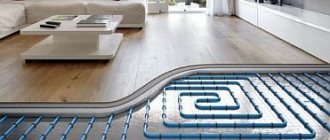
Heating rooms using water heated floors is considered one of the most effective ways in terms of energy savings and uniform heat distribution. As you know, heating is carried out through pipes with coolant laid in a screed. Each room is a separate closed circuit, or even several. Their operation is controlled by one common unit - a comb for heated floors. Information about how this unit functions, the nuances of its assembly and regulation is brought to your attention in this article.
Automatic temperature control of TP
Automatic adjustment of a heated floor can be carried out thermomechanically or electronically using electromechanical actuators that control the operation of shut-off valves.
Thermomechanical control system
It is based on the operation of thermostatic valves or taps with thermal heads that respond to changes in coolant temperature. Various models of such shut-off and control valves are offered today by many manufacturers, for example, Oventrop. However, regardless of the name and type of thermosetting substance used in them (liquid or gas), these are thermomechanical self-regulating mechanisms that are most appropriately installed to control the temperature of one, individual circuit.
The operating principle of thermal valves is simple, which makes them very reliable and fault-tolerant. A copper, brass or bronze core installed in the device body, heated by the passing coolant flow, transfers the temperature to the thermosetting filler. In turn, the thermosetting element, which increases in volume, pushes the core, which, by moving the valve, gradually blocks the circulation of the heated liquid.
The thermostatic valve for heated floors, in addition to being installed on the distribution comb, can be mounted in a separate “unibox” type assembly. Such assemblies also include automatic air vents, which, together with thermostats, are placed in compact boxes (boxes). The use of a “unibox” allows you to adjust the temperature in a separate branch of the TP without being tied to bulky manifold cabinets, which is especially convenient with a small number of circuits.
In addition, thermomechanical floor heating controllers can have remote air sensitive elements. They allow you to configure them to control the flow of coolant not according to its temperature, but according to the air temperature in the rooms. The principle of their operation is the same, only the thermosetting substance is much more sensitive. It is advisable to install an air thermal head for simultaneous control of several circuits in one room, where water underfloor heating is the only source of heating.
Electronic control system
It consists of electronic thermometers, a controller and electric drives (actuators, servos). Electric drive mechanisms can be attached to the mixing heads of conventional control valves (valves) or be part of their design. The change in coolant supply intensity is carried out in accordance with specified threshold values. The measuring medium for the temperature sensors of the automatic floor heating temperature controller can be both the coolant and the air in the premises.
Important! Such control equipment is quite expensive, but at the same time it is capable of providing optimal operating conditions for underfloor heating and maximum energy savings. In addition, electronic regulators allow programming of the TP with binding of its operating modes to different time periods, which guarantees the user maximum thermal comfort.
The influence of the coolant supply method on the choice of control technology
Control of heating of water heated floors equipped with their own heat pumps occurs under conditions of continuous supply of coolant at high speed and in large volumes. Such systems use the admixture of cooled liquid to the supply stream to bring its energy parameters to the specified ones. The mixing is carried out in pumping and mixing units (PMU), which lower the temperature of the coolant from the primary high-temperature heating circuit to the design ones. Further adjustment of the temperature of the heated floor is carried out on the combs and has already been described above. NSU blocks provide optimal operating conditions for underfloor heating, and also allow it to be installed in unlimited areas.
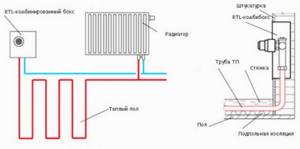
However, with a small TP quadrature it is possible to avoid the use of expensive mixing units. The temperature of the coolant for the heated floor, in this case, is maintained by the method of limiting flows or by the RTL scheme. The functional principle of the circuit is the portion supply of coolant into the circuits. In each branch, the active element of the thermostatic valve, installed on the return line, having warmed up to the set temperature maximum, blocks the flow of working fluid. The heat gradually released by the coolant is dissipated in the concrete screed. After the system has cooled to the minimum temperature threshold, the valve opens and the batch feed cycle is repeated.
The simplicity of RTL control of underfloor heating makes it especially attractive. After all, it is enough to use a set of thermomechanical valves installed on the comb, or compact “unibox” type assemblies. However, when choosing an RTL scheme, you should not forget about its limitations:
- it is applicable only in heated floors made under a thick concrete screed, which plays the role of a heat accumulator;
- For efficient operation, in addition to good heat removal, the circuit pipelines must have minimal hydraulic resistance. This is necessary to quickly update the coolant. Taking into account the absence of a heat pump in the TP system, such conditions are met if the length of the branches does not exceed 50 m with a pipeline diameter of 16 mm. If it is necessary to slightly increase the length of the circuits, it is recommended to use pipes Ø 20 mm.
Important! The use of pipes of different diameters in one system (on one collector) of underfloor heating with RTL control is strongly not recommended.
Setting up a comb for heated floors
Factory products undergo bench testing, as evidenced by accompanying documents containing complete information about all hydrotests performed under special conditions. The use of such compact devices with a guarantee of tightness of welded and threaded connections is the best option in any in-house heating systems. Such units are characterized by an ergonomic arrangement of controls, and installation inside special mounting cabinets does not interfere with access to control valves.
After installation, the collector is configured with the servo drive and thermal head removed
The coolant from the supply pipe and the return pipe is mixed inside each outlet or directly in front of the collector, but it is advisable to entrust the calculation of the optimal circuit to specialists.
Regulating the temperature of the floor surface involves performing several sequential actions:
- Set the bypass valve to max, moving it to the 0.6 bar position. Triggering this node during the setup process causes an erroneous result.
- Calculate the balancing valve, using for this purpose the temperature indicators at the return, supply line and outlet of the heating device, under the conditions of a standard coefficient of 0.9 and according to the throughput formula: K = 0.9 × [(tk – to/tp – to) - 1]).
- Set up pumping equipment by calculating the boiling water flow rate and pressure loss on the circuits. It is allowed to set the minimum feed with a gradual addition of speed.
- Balance the branches by fully opening the control units and smoothly closing them to the required position.
It is necessary to adjust the position of the balancing valve as correctly as possible
At the final stage of setting up the comb for the “warm floor” system, the flow rate of the mixing unit is linked with other heating devices.
It should be noted that installing a flow meter will greatly facilitate obtaining accuracy when setting up all components. It is recommended to set the processing parameters of the bypass valve device approximately ten percent lower than the established maximum pressure values of the pumping equipment.
You will learn more about self-installation of water heated floors and analysis of various installation systems in the material: https://pol-master.com/tepliy-pol/vodyanoj-teplyj-pol-svoimi-rukami.html.