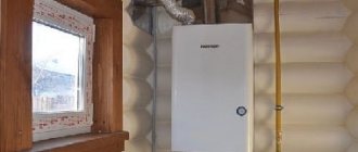
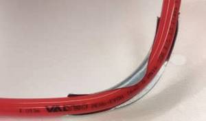
More recently, stoves were installed to heat homes, which were later replaced by more modern water heating using radiators. Warm floors were considered exotic, because the copper pipes that were laid in the screed and through which hot water circulated to heat the floors were very expensive and inaccessible to many. Now you can buy everything for a warm water floor in specialized stores or order it online with delivery to any region of Russia.
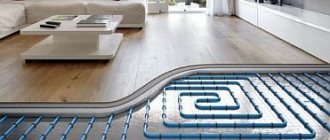
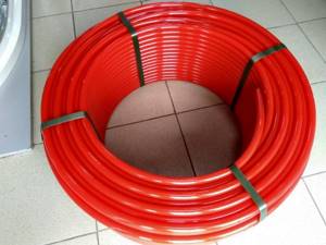
With the advent of relatively inexpensive small-diameter plastic pipes on the market, the situation has changed radically. Plastic pipes have remarkable properties - durability, resistance to coolant temperatures, ease of installation and good thermal conductivity. With the advent of new materials, the scheme of water heated floors in private houses and apartments is becoming increasingly popular.
Lack of calculation of heat losses for heating
This is the biggest mistake when installing a heated floor (or any other heating system). When installing heating system radiators, you should not follow the same standards that are generally accepted in a house without heated floors. Sectional batteries should not be installed according to the number of windows in the room and based on the calculation of the room's area. This can result in a non-functioning system or increased unnecessary heating system installation costs.
If you install heating devices of lower power than required, then the heating will eventually have to be completely redone: install additional radiators or increase the number of sections in the already installed ones.
According to the rules, the installer himself is obliged to make calculations of the number and power of radiators and heated floors. If a specialist offers you to install radiators under each window opening, and the number of sections is determined by your desire or budget, then it is better to refuse immediately. In this case, there is a chance that you will freeze in winter. As a result, you will have to change radiators to more powerful ones, or expand existing ones. Taking into account the cost of installation and dismantling of heating, this amounts to an impressive amount. In addition, you may have to redo the heated floors themselves.
The first thing you need to do before installing a heated floor is to calculate the heat loss. This calculation will show whether the power of the heated floors is enough to heat the building or not. It will allow you to determine the required power of additional heating devices. This calculation allows you to avoid many mistakes.
The calculation takes into account such items as the pitch of the heated floor pipe, the wall thickness and internal diameter of the pipe, the thickness of the reinforcing mesh, the total thickness of the screed, the distance from the load-bearing wall, the thickness of the insulation, the thickness of the screed above the pipe, the thickness and type of floor covering, the thickness of the substrate or a layer of tile adhesive.
Poor or absent insulation between underfloor heating pipes
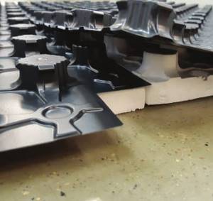
Laying thermal insulation for heated floors
Often, water heated floors are installed without insulation.
Installers believe that heat rises and therefore lay the pipe directly on concrete or on the ground. This approach is unacceptable. The fact is that the thermal conductivity of a concrete screed is 30 or more times greater than that of air. In this regard, thermal energy, according to the laws of physics, will be dissipated throughout the structure and go into the ground.
You will incur high heating costs and are unlikely to feel warm
Floor testing and pressure testing
Before pouring the floor with concrete screed, it is necessary to test and pressure test the water circuit.
The finished heating system is tested as follows:
- the pipeline is filled with hot water;
- for approximately 30 minutes the temperature in the system rises to critical (80ºС - 85ºС).
The final stage of checking the system is pressure testing (high pressure test). For this:
- the pipeline system is filled with cold water;
- all air extractors located in the manifold are turned off;
- The pressure is set at 6 bar for 24 hours.
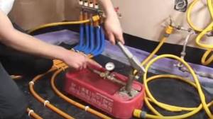
Checking pipes for leaks and high pressure
If, at the end of the pressure test, no excessive expansion or deformation of the pipes is noticed, and the set pressure has not decreased, then the resulting water circuit is completely sealed and suitable for use.
No damper
When heated, materials tend to expand. The screed in which the heated floor pipes are mounted will also expand when heated. This can lead to the pipe simply bursting. As a result, the floor covering becomes deformed. In this regard, special damper tapes must be installed around the perimeter of the heated floor installation. If the area of one heated floor zone is more than 40 m2, it is advisable to divide it into parts. Therefore, there must be compensation gaps.
Connection methods
There are several ways to connect parts of the pipeline during installation:
- compression (crimp) fittings;
- compression fittings;
- electric welded fittings.
The choice of a specific connection type depends on the planned operating characteristics.
To install communications, you may need the following tools:
- Special pipe cutter-scissors. A pipe cutter allows you to cut pipes into sections of the desired size without applying excessive effort. In this case, the cut will be smooth, without burrs, at an angle of 90 degrees. Such a cut will ensure high quality and reliability of the future joint.
- Hydraulic Press.
- Collet expander for increasing the diameter of the pipe before inserting the fitting.
- Pliers.
- Wrenches for tightening the crimp nut.
- Fitting.
When using electric welding fittings, you will need a special welding machine. It can be rented.
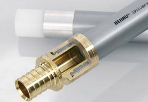
Connection with compression fittings
Installation of cross-linked polyethylene pipes using compression fittings is carried out on water supply lines. Here you will need a minimum of tools - just a pipe cutter and a wrench or adjustable wrench.
We recommend that you read: How to select and install ventilation clamps for securing air ducts
The work algorithm is as follows:
- The fitting is unscrewed and a ferrule nut and split ring are sequentially placed on the end of the pipe.
- The split ring is installed 1 mm from the edge of the cut.
- The fitting of the connecting piece is inserted into the pipe until it stops.
- Carefully screw the ferrule nut onto the fitting, trying to tighten it tightly, but not overtighten it.

Due to the plasticity of polyethylene, such a connection does not require additional sealing. It can be quickly disassembled if necessary.
Press fittings
The use of press fittings eliminates the disassembly of communications without damage. The connection is reliable, but not separable. For work you need a collet expander and a press fitting.
Connection installation procedure:
- A press ring (press sleeve) is put on the prepared section of pipe, moving it from the edge.
- An expander is inserted into the pipe and stretched to the size of the fitting.
- The expander is removed and the connecting piece is inserted in its place.
- Thanks to the molecular memory of the material, the pipe contracts and tightly grips the connecting fitting.
- Additional fixation is carried out by pulling the press ring onto the edge of the pipe and pressing it with a hand press.
In this connection there is no external pressure on the connection point. Quality and reliability are due to the special properties of cross-linked polyethylene itself.
Electric welding connection
Electric welding on polyethylene communications is carried out only using special fittings.
Work order:
- An electric welded coupling is placed on the prepared pipes.
- A welding machine is connected to the contacts on the fitting.
- Welding occurs when the material is heated to a temperature of 170 degrees.
- The heating time is set automatically, depending on the diameter of the pipeline. If the welding machine does not have such a function, then the welding time and temperature should be found in the documentation for the fitting.
- At the end of the welding process, the machine is turned off and the connection is allowed to cool.
This connection method is the most expensive, but also the most reliable. There are no restrictions on temperature and pressure for the operation of pipelines using electric welded fittings. The connection is stronger than the pipes themselves.
We recommend that you familiarize yourself with: SML pipe and socketless cast iron sewerage
Heated floor pipe circuit length
If you are going to install a heated floor with your own hands , then you should take into account that long circuits create high hydraulic resistance. As a result, the coolant in the pipes begins to circulate poorly. In this regard, it is recommended that when laying pipes with a diameter of 16 mm, make the circuits no more than 100 m long, so as not to buy a more expensive powerful circulation pump. As a result of installing such a pump:
- Pipe wear increases.
- A higher power pump costs more.
- Excessive consumption of electricity is increasing.
- There is noise in the floor pipes.
All this can lead to such a system not working.
Watch the video about the installation length of a heated floor pipe:
Incorrect regulation of heated floors
Adjustments are most often made on the underfloor heating manifold
Often, inexperienced installers install a water-heated floor at home without regulators, connecting the collectors directly. This leads to an increase in room temperature. As a result, you will either be hot or stuffy. It is necessary to remember that the temperature of the floor surface should not be higher than 350C. This cannot be achieved without properly installed mixing units and regulators.
Construction and materials of heated floors
- This is done for two reasons:
- to avoid overheating of the floor in areas where supply pipelines are laid;
- Heat losses in the supply sections, as a rule, are not taken into account in thermal calculations of a heated floor, and they, if the loop is sufficiently distant from the collector, can be quite significant.
- reduce the pipe pitch ( Table 4
;
Fig. 5 A
); - use a separate loop with an increased coolant temperature ( Fig. 5 B
); - use a separate loop with an increased pipe diameter ( Table 5
); - use a separate loop with an increased coolant temperature, reduced pitch and increased pipe diameter.
- the density of the insulation (expanded polystyrene) under the screed must be at least 40 kg/m3;
- The screed mortar must be workable (plastic). Be sure to use a plasticizer;
- To avoid the appearance of shrinkage cracks, it is recommended to add polypropylene fiber to the solution ( Fig. 7
) at the rate of 1–2 kg of fiber per 1 m3 of solution. For power-loaded floors, steel fiber is used for the same purposes.
After laying the pipes, an as-built diagram should be drawn up to indicate the exact alignment of the pipe axes. This is necessary so that during further work or repairs the pipe is not damaged.
Rice. 4. Thermal insulation of supply pipeline sections
Arrangement of edge zones
In cases where underfloor heating cannot completely compensate for the heat loss of the room, you can try to compensate for the lack of thermal energy by installing edge zones. Edge zones are areas of heated floors with an increased temperature of the floor surface, which are usually installed along external walls to a width of no more than 1 m.
- The specific heat flux in the edge zones can be increased in several ways:
Table 4. Effect of pipe pitch on the change in specific heat flux (relative to a pitch of 15 cm)
| Pipe pitch, cm | 7,5 | 10 | 15 | 20 | 25 | 30 |
| Change in specific heat flow, all other things being equal, % | +13 | +8 | 0 | –8 | –15 | –22 |
Table 5. Influence of pipe diameter on the change in specific heat flow (relative to the outer diameter of 16 mm)
| Pipe outer diameter, mm | 12 | 16 | 20 | 25 |
| Change in specific heat flow, all other things being equal, % | 9 | 0 | +10 | +25 |
The use of separate loops with increased coolant temperature makes sense when there are several rooms with edge zones. In this case, the pipelines of the edge zones can be served by a separate pumping and mixing unit.
In any case, the temperature of the floor surface in the edge zones should not exceed 31 ° C, as well as the temperature for which the finishing floor covering is designed.
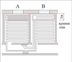
Rice. 5. Options for installing edge zones of heated floors
Requirements for the screed
The heated floor screed must have sufficient density to reduce heat loss from the pipelines, and also have sufficient strength to withstand loads on the floor.
As a rule, the screed is made from cement-sand mortar or concrete using a plasticizer. The plasticizer allows you to make the screed more dense, without air inclusions, which significantly reduces heat loss and increases the strength of the screed. However, not all plasticizers are suitable for this purpose. For heated floors, special non-air-entraining plasticizers are produced (for example, shown in Fig. 6
plasticizer "Silar" or Kilma Therm), based on fine flaky particles of mineral materials with a low coefficient of friction.
Most other plasticizers used in construction are air-entraining, which will result in a decrease in the strength and thermal conductivity of the screed. As a rule, the plasticizer consumption is 3–5 liters per m3 of mortar or concrete. The minimum thickness of the screed above the pipes should not be less than 30 mm.
In the case when it is necessary to make a 20 mm screed, an additional layer of reinforcing mesh must be laid over the pipes. Even a reinforced screed should not be thinner than 20 mm. The reasons for the appearance of cracks in a heated floor screed may be low strength of the insulation, poor compaction of the mixture during installation, lack of plasticizer in the mixture, or too thick a screed (shrinkage cracks).
To avoid cracks, you should adhere to the following rules:
Rice. 6. Plasticizer "Silar"
Rice. 7. Polypropylene fiber
After pouring, the screed should gain sufficient strength. After three days under natural hardening conditions (without heating), it gains 50% strength, and in seven days – 70%. Full strength gain to the design grade occurs after 28 days. Based on this, it is recommended to start the “warm floor” no earlier than three days after pouring. It must be remembered that filling the heated floor with a solution must be done by filling the floor pipelines with coolant with a pressure of at least 3 bar.
In table 6
Recipes of recommended solutions for installing screeds of heated floors installed using the “wet” method are given.
Table 6. Compositions of cement-sand mortars
| Brand of solution | Composition of the solution in parts by weight | ||||
| Water | Cement1 | Sand2 | Fiber PP3 | Plasticizer3 | |
| 150 | 0,55 | 1 | 3 | 0,005 | 0,012 |
| 200 | 0,48 | 1 | 2,8 | 0,005 | 0,012 |
| 300 | 0,4 | 1 | 2,5 | 0,004 | 0,011 |
Notes: 1Stamps no less than 400. 2Piece no less than 0.5 mm.
3Recommended use. Requirements for insulation
The insulation layer in the heated floor structure reduces heat loss in the lower direction, thereby increasing the efficiency of underfloor heating (the ratio of heat flow in the direction of the heated room to the total heat flow from the underfloor heating pipes).
In addition to thermal insulation properties, the insulation must have strength that ensures the absorption of loads from the own weight of the overlying floor structure and the payload on the floor. These conditions are best met by expanded polystyrene slabs with a density of at least 40 kg/m3.
The design of the heated floor must be designed to withstand the loads set out in the table. 7
.
Table 7. Floor loads
| Purpose of the premises | Load, kg/m2 |
| Attics | 70 |
| Residential, educational, sleeping, hospital wards | 150 |
| Offices, classrooms, cabins, classrooms, laboratories | 200 |
| Dining rooms in cafes, restaurants, canteens | 300 |
| Places where there may be crowds of people | 400 |
| Archives, book depositories | 500 |
When calculating, the thickness of the insulation layer should be determined from the condition that heat loss in the lower position does not exceed 10% of the total heat flow from the pipes.
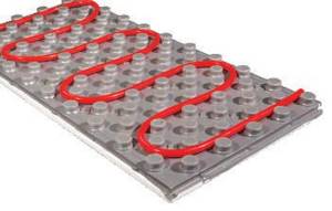
Especially for the installation of water heated floors, thermal insulation boards with protrusions for fixing the heated floor pipes are produced. Connecting the plates to each other can be done in different ways. For example, in Ecopol 20 slabs, the connection of the slabs is ensured by “fastening” the release of the polystyrene cover layer onto the adjacent slab ( Fig. 8
).
Rice. 8. “Lock” connection of “Ekopol 20” slabs
And boards such as EasyFix have a tongue-and-groove connection ( Fig. 9
).
These boards are available with or without polystyrene coating. The main technical characteristics of the Ecopol 20 and EasyFix slabs are given in table.
8 .
Rice. 7. EasyFix plate
The protrusions of the slabs are designed in such a way that they provide a pipe pitch (raster) that is a multiple of 50 mm when laying straight, and a multiple of 70 mm when laying diagonally. Methods for attaching pipes to insulation boards that do not have protrusions are described in the next section.
Table 8. Technical characteristics of polystyrene foam boards for heated floors
| Characteristics, units measurements | Characteristic value for slabs | ||
| "Ecopol 20" | EasyFix | ||
| Coated | Without cover | ||
| Thickness without protrusions, mm | 20 | 20 | 20 |
| Dimensions, m | 1.1 x 0.8 | 1.0 x 0.5 | 1.0 x 0.5 |
| Height of protrusions, mm | 18 | 20 | 20 |
| Density, kg/m3 | 30 | 45 | 45 |
| Outer diameter of fixed pipes, mm | 16 | 16; 20 | 16; 20 |
| Thermal conductivity coefficient, W/m K | 0,035 | 0,036 | 0,036 |
| Compressive strength at 10%, deformation, kPa | 190 | 300 | 300 |
| Bending strength, kPa | 200 | 500 | 500 |
| Noise absorption, dB | 30 | 23 | 23 |
Pipe fastening
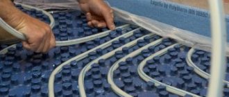
Fastening of heated floor pipes can be carried out in various ways, both “handicraft” and using special fasteners and tools.
When using thermal insulation boards with protrusions (“bosses”), as described in the previous section, no additional fastening of the pipes is required, since the protrusions ensure reliable fixation of the pipes to the thermal insulation ( Fig. 10
).

Rice. 10. Fastening pipes between the “bosses” of thermal insulation boards
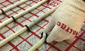
In the case when slabs without protrusions are used, many installers attach the pipes to the reinforcing mesh using plastic clamps ( Fig. 11
).
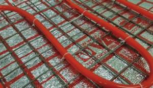
Rice. 11. Fastening pipes with clamps to the mesh
Fastening pipes to the mesh using wire ties is not permitted.
On sale you can find special plastic clips that are designed for attaching pipes to reinforcing mesh ( Fig. 12
).
Rice. 12. Fastening pipes to the mesh using plastic clips
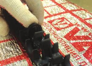
Plastic harpoon clamps are quite convenient to use, reliably fixing pipes to flat insulation. The staples can also be installed manually ( Fig. 13
), however, when using a special stapler for harpoon staples (tacker), the process of attaching heated floor pipes is significantly accelerated and does not require an inclined position of the installer (
Fig. 14
).
Rice. 13. Installing harpoon shackles manually
Rice. 14. Fastening pipes with brackets using a tucker
The distance between individual pipe fixing points depends on the material from which the pipe is made ( Table 9
).
You can fasten pipes to the insulation with special plastic clamp bars ( Fig. 15
).
Rice. 15. Fastening heated floor pipes using clamp bars
Table 9. Recommended maximum distances between mounting points for underfloor heating pipes
| Pipe type | Distances between attachment points, cm | |
| On straight sections | At turning angles | |
| PEX-AL-PEX | 50 | 50 |
| PEX-EVOH | 20 | 10 |
| PE-RT | 30 | 15 |
For example, the SHM.1620 tire allows you to fix pipes with an outer diameter of 16 and 20 mm. It is a plastic track 50 cm long. The tire can be attached to the thermal insulation with harpoon clamps ( Fig. 16
), and can also be mounted on a concrete base using dowels. Locks are provided at both ends of the tire to secure the tracks together along their length. Tire width 40 mm, height – 32 mm. The minimum pipe laying step when using this tire is 50 mm. Tires SHM.1620 are supplied in packs of 20 pieces. (10 m).
Rice. 16. Fastening the tire with a harpoon clamp to the thermal insulation
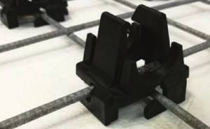
It is recommended to install rotation locks in places where pipes exit from the screed to connect them to the collectors ( Fig. 17
). This protects the pipes themselves from damage, and the screed from cracking at the junctions with the pipes. The use of rotation locks is especially important when using PEX-EVOH and PE-RT pipes, since these pipes do not retain the shape given to them during installation without reliable fixation. In addition, the PEX material has a shape memory effect, so when the coolant in them is heated, the pipes will tend to straighten.
Rice. 17. Rotation clamp VT.491 made of galvanized steel (available for pipes with a diameter of 16 and 20 mm)
Screed reinforcement
- The reinforcing mesh in the construction of a wet heated floor is laid on top of the insulation layer. The grid performs the following functions:
- perceives tensile forces when the heated floor slab bends;
- blocks channels in the insulation layer when pipelines of other systems (radiator heating, water supply, sewerage) are laid in the floor structure ( Fig. 18
); - is a convenient frame for fastening underfloor heating pipes.
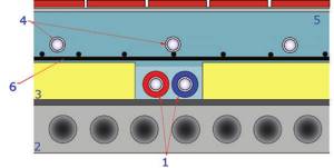
Rice. 19. Laying pipelines of other engineering systems in the heated floor structure: 1 – radiator heating pipes; 2 – floor slab; 3 – layer of insulation (expanded polystyrene); 4 – heated floor pipes; 5 – screed; 6 – reinforcing mesh.
A number of imported manufacturers supply special galvanized mesh for underfloor heating with mesh sizes of 150 x 150 mm. In domestic construction practice, masonry mesh made of reinforcing wire ВрI Ø 5 mm with a mesh pitch of 50 x 50 mm is more often used.
Requirements for finishing the floor
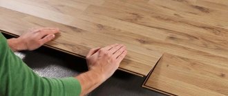
The effect of a warm floor is best felt with floor coverings made of materials with a high thermal conductivity coefficient (ceramic tiles, concrete, self-leveling floors, baseless linoleum, laminate, etc.). If carpet is used, it must have a sign of suitability for use on a warm base ( Fig. 20
).

Rice. 20. Carpet suitability mark
Other synthetic coatings (linoleum, relin, laminated boards, plastic compound, PVC tiles, etc.) must have signs indicating the absence of toxic emissions at elevated base temperatures ( Fig. 21
).
Rice. 21. Floor covering suitability signs
Parquet, parquet boards and boards can also be used as a covering for heated floors, but the temperature on the floor surface should not exceed 26 ° C and the mixing unit must include a safety thermostat. It should also be taken into account that the moisture content of natural wood flooring materials should not exceed 9%. Work on laying parquet or plank flooring is permitted only when the room temperature is not lower than 18 ° C and the humidity is not more than 40%.
Steam and waterproofing
When using the “wet” method of installing heated floors on floors, if the architectural and construction part of the project does not provide for vapor or waterproofing, it is recommended to lay a layer of glassine over the leveled floor to prevent the flow of cement milk through the floor during pouring the screed, as well as to avoid the formation of condensation between the insulation and the concrete base.
If the project provides for an interfloor vapor barrier, then additional waterproofing is not necessary.
In wet rooms (bathrooms, lavatories, showers, etc.), in addition to the vapor barrier under the insulation, waterproofing is installed in the usual manner on top of the heated floor screed.
Many suppliers of underfloor heating system elements recommend laying a layer of aluminum foil on top of the insulation layer. Ready-made foil-coated thermal insulation mats and slabs are also produced.
In cases where heated floor pipes are installed in an air gap (for example, in floors along joists), foiling the thermal insulation makes it possible to reflect most of the radiant heat flow directed downwards, thereby increasing the efficiency of the system. The same role is played by foil when constructing porous (gas or foam concrete) screeds.
If the screed is made from a dense cement-sand mixture, foiling the thermal insulation can only be justified as additional waterproofing, since the reflective properties of the foil cannot manifest themselves in this case due to the absence of an air/solid boundary.
It must be borne in mind that the layer of aluminum foil poured with cement mortar must have a protective coating of polyethylene film, otherwise, under the influence of the highly alkaline environment of the cement mortar (pH = 12.4), the aluminum will quickly collapse.
Expansion joints
The thickness of the expansion joint in heated floors made using the “wet” method is calculated based on the coefficient of linear expansion of the cement-sand screed αst = 13x10-6 1/ °C.
For rooms with a long side of less than 10 m, it is sufficient to use a 5 mm thick seam.
Expansion joints in “wet” heated floors are filled with elastic material of the calculated thickness. It is recommended to use foam polyethylene damper tape for seams.
In general, the calculation of a seam in a “wet” heated floor is carried out according to the formula: b = 0.55 x L, where b
– seam thickness in mm;
L
– length of the room in meters.
- If a standard 5 mm thick polyethylene foam tape is used as a suture material, it is necessary to install expansion joints in the following places:
- along walls and partitions;
- when the floor slab size is more than 40 m2;
- in the center of the doorways (under the threshold). If the warm floor is located on both sides of the doorway, then the damper tape under the threshold is laid in two layers;
- with floor length over 8 m;
- in places of incoming corners.
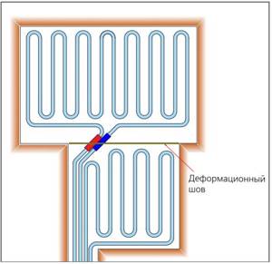
Rice. 22. Expansion joint in a room with incoming corners
Pipes crossing the expansion joint must be laid in a corrugated casing at a distance of 200 mm on both sides of the seam. The ideal solution is when the pipe crosses the seam at an angle of 45° ( Fig. 22
).
Screed too thin or too thick
A screed that is too thin can prevent the heated floor from heating evenly. A thick screed can significantly increase the heating and cooling time of a heated floor. It is very uncomfortable. There are especially problems with cooling. When the house warms up to the desired temperature, the boiler will automatically turn off, and the floors will continue to radiate heat into the room. As a result, the floor covering will become very hot in the evening. At night, when the room temperature drops and the boiler turns on, the floor will remain cold until the morning.
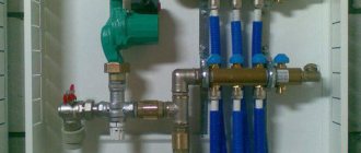
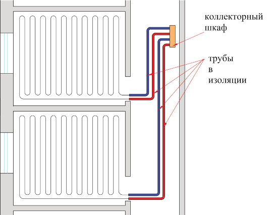
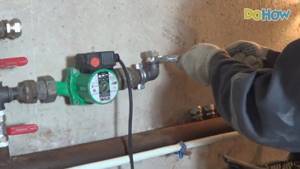
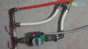
Connecting the return pipe and heated floor in the basement
To quickly warm up the heated floor, we need a circulation pump. We connect it to the return pipe using adapters.
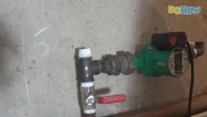
Additionally, we will install two taps in this system. The upper valve will shut off the natural circulation, and the lower one will completely block the entrance to the return pipe.
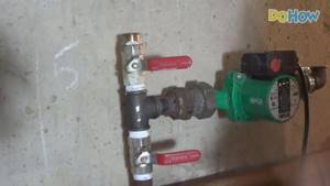
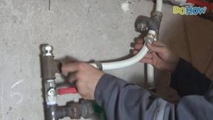
Let's assemble the necessary connections for the return pipe and heated floor.
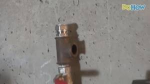
To simplify the work, we will use detachable adapters for metal-plastic pipes.
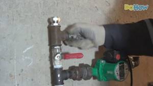
This regulating system and the pump itself are additionally attached to the wall.
It should be noted that this system is assembled with a slight slope to ensure air outlet.
We cut off the excess water floor pipe.
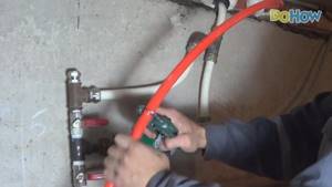
Finally, we connect the underfloor heating pipe to our control system.
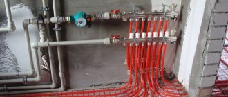
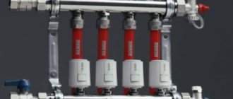
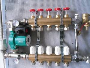
Lack of air vents in distribution manifolds
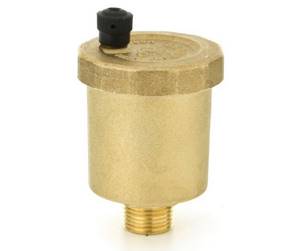
Example of an air vent
Air is the enemy of any hydraulic heating system. Air should be released from the system periodically. If there is no way to release it, sooner or later an air lock will appear, which will block the circulation of coolant in the system. The result is a system that doesn't work well or doesn't work at all. In this regard, either Mayevsky cranes or auto-ventilators are installed on the collectors.
Incorrect order of connecting the circuits to the manifold
Installing a heated floor with your own hands often leads to this most common mistake. It occurs when the circuit itself and the return circuit are placed on the same collector. As a result, this circuit does not work. It looks like this. There is a supply manifold on top. The pipe from it goes to the water supply to the system and returns to the same collector, to another outlet. The result is a dead loop.
Sometimes during installation the sequence of connecting the circuits to the collectors is violated. When installing a collector, it is desirable that each circuit be connected to the collector in order, that is, the supply of this circuit should coincide with the same connection point on the return collector. The next circuit is the second valve on the supply and the second valve on the return manifold. Due to the change of order by installers, difficulties may arise with the regulation of the circuit, which can lead to a non-functional circuit or an entire zone. This kind of underfloor heating system can be very difficult to set up.
How is the main line installed?
For water underfloor heating you will need a flat subfloor surface. It is recommended to use a screed, self-leveling floor, or use a self-leveling mixture. The water pipeline is laid on a dry surface. It is recommended to use insulating materials so that all the heat from the water circuit is directed to the floor.
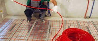
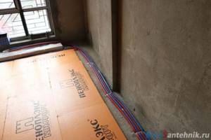
- The base is covered with a thin plastic film.
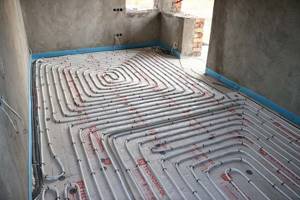
- I'm laying insulation. It is recommended to use a contour coating made of polystyrene foam "Rehau". The PEX underfloor heating pipe fits well into the contour of the coating. The highway is laid in a “snake” or “snail” pattern, outlining the protruding contours of the bosses. They crimp the pipe from the sides, securely fixing it in a certain place.
- The main is connected to a collector, which has an outlet for hot and chilled water. Connect the entire system to the heating boiler. Testing the heating system.
- The heated floor with PEX pipes is poured with a concrete screed up to 8 cm deep.
We recommend: How to install heated floors under cork?
Foam boards are used as insulation for the subfloor. Foil material is placed on the plates. This is a reflective screen that will direct the heat upward. To strengthen the highway, reinforced mesh and mounting brackets are used.
The staples are installed on the mesh with a certain pitch. They are made of plastic and have teeth pointing down. The teeth will not allow the water circuit to change position or exit the groove.
PEX pipes are used not only for underfloor heating, but also for cold and hot water supply. No corrosion or salt deposits form on the inner surface of the product, which prolongs the service life of the water circuit.
When heated, cross-linked polyethylene PEX does not emit toxic substances. The products are used in pharmaceutical enterprises. Cross-linked polyethylene for PEX-a and PEX-c is included in the group of environmentally friendly products.
YouTube responded with an error: The request cannot be completed because you have exceeded your quota.
- Related Posts
- How to install heated flooring under a shower stall?
- How is an infrared heated floor installed?
- What are the characteristics of Rehau pipes for underfloor heating?
- What equipment is needed for water heated floors?
- How much does underfloor heating cost?
- Rating of manufacturers of heated floors for tiles
Damage or clogging of pipes during work
It can be:
- Pipe breaks during installation of heated floors.
- Compression of pipes during screed installation.
- Drilling or all kinds of punctures.
- Pipe clogging with sand or cement mortars during construction work.
In general, this includes everything that will interfere with the normal circulation of the coolant.
According to our statistics, pipe punctures are quite common. Then someone will drill the floors for some reason, or make some kind of grooves. This is also possible during subsequent renovation work around the house. Then some painter or electrician will put a platform on the heated floor pipes before they make the screed. This needs to be monitored.
Incorrect connection of underfloor heating pipes and radiators
It must be remembered that radiator pipes and underfloor heating pipes have different temperature conditions.
Installation of a water heated floor requires additional installation of collectors. Connecting a heated floor with your own hands and a heating system to one collector will make it difficult to balance the system in the future. This is due to the fact that the coolant in the radiators must warm up to 600C - 800C, and the temperature of the heated floor should not exceed 350C.
Therefore, these systems should not be combined in one collector unit.
Options for heating systems using underfloor heating
With the advent of new technologies, equipment and plastic pipes intended for use in heating circuits, along with traditional radiator heating, specialists began to connect underfloor heating systems to heating boilers through a manifold, which create additional comfort in the house. This system is used in regions with extremely low temperatures in winter.
As a result of careful calculations by heating engineering specialists, a completely new scheme for a warm water floor was created, which turned into the main method of heating a house. When implementing this scheme, plastic pipelines are laid under the floors of all residential premises. There are no batteries or piping.
Therefore, there are two main options for heating systems with heated floors:
- Combined heating scheme. The home is heated simultaneously through heating devices (radiators) and additionally using heated floors.
- Only heated floors are used to heat the entire house.
Lack of hydraulic testing of the system after its installation
This is the most common mistake. It is recommended to check the heating system several times during the installation process yourself. When installing a new heating system in a house or during a major renovation, pressure testing should be done several times. The first time it is performed is at the moment when the system has just been installed. The second time, pressure testing should be done after installing drywall in the same room where we are installing heated floors. The third crimping occurs after rough finishing work has been completed. It is advisable to complete this before laying tiles, gluing wallpaper, or installing baseboards.