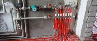
Hello readers of my blog! Today we will talk about how to properly install a manifold for a heated floor with your own hands. It would seem that the matter is not tricky, but when you are faced with this problem, you have to think about how to do it correctly, what preparation to do, what materials to choose. Thus, I decided that this article would be useful to someone, and I am devoting my efforts to this subject. In it I will answer a number of questions that will arise immediately before How to properly install a manifold for a heated floor with your own hands, and some even after that. This topic is quite broad, because before work, thorough preparation is necessary, but how to do this? And this is a separate topic. You can learn about all this in great detail in the article below. How to properly install a manifold for a heated floor
Traditional radiators, for many years considered the only possible source of heat, are gradually giving way to systems of warm floors and ceilings. Many people experience innovative methods and are very satisfied. However, heated floors can hardly be called an innovation.
They have proven themselves well and become a fairly common heating method.
Such systems can run on electricity or use hot water energy.
According to experts, a water heated floor is considered the most effective and practical to assemble with your own hands, but it is quite possible to assemble it if desired.
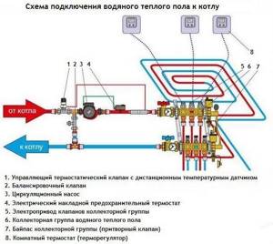
Unit #1 - water heating boiler
The boiler selected for installation must have sufficient power to cope with the heating of the coolant during peak operation of the circuits. In addition, it should have a small power reserve.
Approximately, this value should be the total power of all maintained heated floors, increased by 15-20%. In addition, a circulation pump is needed. Most often, it is already included in most boiler models.
An additional device may be needed only if the area of the heated room is more than 120-150 square meters. m. In case of preventive maintenance or repair of the boiler without draining water from the entire system, shut-off valves are installed at the outlet and inlet of the heating device.
Installation
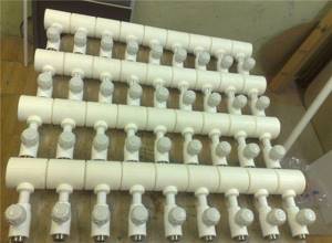
Factory-made manifolds are designed so that assembling them with your own hands is as simple as possible. All parts for assembling the distribution elements are included in the kit; you just need to assemble them in the correct order and connect them to the system pipes carrying the coolant. All steps for installing the collector can be seen in the video:
Most manifolds are made from plumbing grade alloy steel or brass alloys. Almost all connections are provided with rubber gaskets, so it is easy to ensure sealing, even without resorting to the use of tow or FUM tape.
Unit #2 - collector
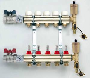
The collector is a device responsible for distributing hot water through heating circuits, as well as setting up and adjusting heated floors. The device must have a sufficient number of terminals to connect all circuits to them.
The simplest models are equipped only with shut-off valves. They are extremely cheap, but do not provide even a minimal opportunity to customize the system.
Devices with control valves allow you to adjust the water flow for each circuit, which allows you to adjust the heated floor for the most uniform heating of the premises.
The manifold of any model must be equipped with a drain outlet and a special air vent valve. The most convenient to use are devices with servo drives on valves, equipped with pre-mixers that mix the heated water supplied to the system with the cooled water returning and thereby regulate its temperature.
Such a device fully automates the functioning of a heated floor, but its cost is very high.
Manifold with servomotors on valves and pre-mixer. Necessary system adjustments are made automatically
Purpose of the collector
The distributor in the heating system is a very important component, as necessary as a pump or boiler. This device serves as a distribution area and ensures the supply of heated water to all appliances connected to the system. To ensure uninterrupted operation of each individual branch of the circuit, the collector is additionally equipped with various air filters and thermometers, temperature control and shut-off sensors, and thermal control devices.
The collector is an element that, according to technical parameters, mixes and distributes warm water from parallel circuits of the heating system. Due to its large cross-section and low speed, the specified parameters are equalized.
How can water floors be installed?
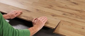
Warm water floors can be laid in different ways - by laying and using concreting. Let's take a closer look at each of them.
- Concreting. The pipes through which the coolant circulates are laid as required on the prepared base and filled with concrete screed. The main disadvantages: labor-intensive “wet” work, the heavy weight of the system and the complexity of its dismantling.
- Laying method. Involves laying pipes in a specially assembled deck.
It can consist of plastic modules or wooden blocks with grooves prepared in them for installing pipes. Wooden mounting modules can also be found on sale. The main disadvantage is that the system takes longer to warm up than a concrete one.
Collector design and connection diagrams
The use of a modern collector has a number of advantages, and without this element, it is impossible to ensure efficient and safe operation of this type of heating:
- safety , the possibility of supplying very hot water to the system is eliminated;
- the ability to control the temperature in each individual circuit , and installing a thermostat and electric drive allows you to automate this process and adjust the floor temperature, depending on weather conditions;
- You can also adjust the temperature manually, but this method should not be used if a high-temperature hot water source is used;
- It is possible to limit the temperature; for this, a certain level is set on the thermostatic head, above which water will not be supplied to the heating circuits.
A water heated floor collector consists of a system of pipes that are assembled in a certain order, which allows you to combine several water flows into one.
Several methods of connecting pipes are used:
- parallel;
- sequential;
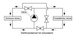
- mixed.

If a parallel system , then there is a high probability of losing some heat, but this option allows you to install a two-way valve, which is an additional control element.
The most productive is the sequential system . The combined system combines the advantages of the previous two; its installation is quick and simple.
What needs to be done before installation?
Proper installation of a warm water floor requires careful preparatory work. During their course, all the little things must be taken into account, on which the effective functioning of the structure will subsequently depend:
It is best to entrust the design of the future system to specialists, since it is quite difficult to make independent calculations.
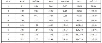
It will be necessary to determine the length of the pipe, the pitch of its installation and the power of the heating circuit, if there are several of them, then for each separately. In this case, many nuances and parameters are taken into account. There are special calculation programs that many people use.
However, you need to understand that a flaw in the calculations will lead to a decrease in efficiency or simply the impossibility of functioning of the entire system. Equipment for heated floors must be of high quality, manufactured and purchased from a reliable company that offers good guarantees.
It will be cheaper to pay for a quality product than to subsequently constantly shell out decent sums for expensive and labor-intensive repairs. To minimize the thermal load on the screed and prevent it from cracking, the system should be divided into sections of no more than 40 square meters. m. The base for heated floors must be carefully prepared.
It must be clean and level, differences of more than 5 mm are not allowed. To prevent heat loss, a heat-insulating layer must be spread on the prepared base, with a height of 3 to 15 cm, depending on the operating temperature of the coolant. This could be special heat-insulating materials or mats designed for warm water floors. The latter can be equipped with pipe mounts, so-called bosses, which is very convenient.
A damper tape is laid around the perimeter of the room and between the installation areas, which can compensate for temperature fluctuations of the screed.
Mats with bosses designed for water heated floors are very comfortable. They not only act as a heat insulator, but also secure the pipes in place
When drawing up a laying scheme, you need to avoid a large number of pipe joints, which carry the potential danger of leaks under the floor. It is best to arrange the safest option, where connections are present only at the outlet and inlet of the collector. In this case, the length of the solid pipe should not be more than 90 m, otherwise the temperature of the circulating coolant may drop.
Where and how to install the collector correctly?
Installation of the collector and its connection to the water heated floor system should be carried out using the following recommendations:
Correct connection of the collector
- There should be no more than 9 circuits per collector unit. Otherwise there should be several of them;
- The collector must be installed in the middle of the house. In this case, all contours should have approximately the same length;
- the collector unit is preferably placed at the highest point;
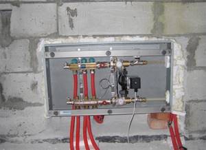
- installation of all elements of the unit is carried out in a special cabinet, which must be located in a place accessible to a limited number of people.
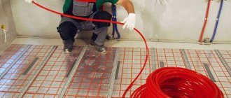
Laying a heated water floor in a screed
Work begins with determining the installation location of the collector, which is most often “hidden” in a special cabinet. It is usually mounted on the wall.
The device should be placed so that the length of pipes from each of the heated rooms is approximately the same. You can bring the collector closer to the largest contours.
The main thing is that it is installed above the level of the heated floor, without venting pipes upward, otherwise there may be problems in the air exhaust system.
The next stage is marking the prepared base, taking into account the division into sectors of 40 square meters. m. Then a thermal insulation layer and damper tape are laid.
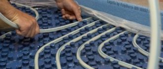
Next, the reinforcing mesh is laid on which the pipes will subsequently be attached. If special mats are chosen as thermal insulation, the mesh will not be needed. You can start laying out the pipeline.
It can be done in different ways: snake, spiral, loops, etc. The laying step varies from 10 to 40 cm, and the distance from the wall to the nearest pipe cannot be less than 8 cm.
The pipes are secured to the reinforcing mesh using plastic clamps.
It is important not to pinch the part; it should be in a loose loop, otherwise, under the influence of heat, the pipe will expand and may become deformed in the area of tight pressing. The fastening clamps are installed in 1 m increments. You must work with the pipe very carefully.
Most often it is supplied in the form of a coil. Pulling it out from there one by one is unacceptable. You should gradually, as it is laid, unwind the pipe, placing and securing the element on the floor.
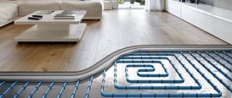
There are several options for laying pipes for heated floors. The most common:
- spiral,
- snake,
- loops,
- double snail
Rotations of the part are performed very carefully, observing the minimum bend radius requirements. Typically it is about five pipe diameters. If you squeeze the product, a whitish crease area will form.
It indicates a sharp stretching of the fragment and loss of its strength characteristics, which leads to an increased risk of pipe rupture. It is not recommended to install a part with such a defect in a heated floor system. The damaged fragment must be replaced, which leads to the appearance of unnecessary joints in the pipeline, and this is also undesirable.
The laid pipes must be connected to the collector. For this purpose, special compression fittings or Eurocone systems are used.
The beginning of the pipe of each heating circuit is connected to the supply outlet of the manifold, thus the number of outlets and circuits must match. The end of the pipeline is connected to the return manifold. If the pipe is laid near an expansion joint, a corrugated tube must be put on it.
Upon completion of installation, the system must be checked.
To do this, water is poured into the pipeline and a pressure of 5-6 bar is applied throughout the day. After which a careful inspection is carried out to identify possible expansions on the pipes or leaks. More details in the video:
If the test run was successful, proceed to pouring the screed.
It should only be carried out with pipes filled with water and operating pressure in them. After pouring, the screed will dry completely no earlier than after 28 days. After this time, you can begin work on installing the flooring.
Before you start pouring the screed, the pipes are attached to the reinforcing mesh using special plastic clamps that prevent the elements from moving
There are some nuances regarding the formation of screeds over water-heated floors. They depend on the type of flooring that will be laid on top of it. If you plan to install tiles, the screed should be 3-5 cm high or the distribution of pipes should have intervals of about 10-15 cm.
Otherwise, according to the principle of heat distribution, there is a danger of the appearance of a “thermal zebra”, which can be clearly felt by the foot. But under laminate or linoleum it is better to lay a thinner screed. In this case, in order to strengthen the structure, another reinforcing mesh is laid on top of the heated floor, which will also reduce the thermal path to the surface of the coating.
You can find many recommendations on how to make warm water floors yourself.
However, you need to clearly understand that this is a complex and responsible undertaking. A pipeline laid in a screed is practically beyond repair, and if installation or design errors are discovered at this stage, it will be extremely difficult to correct them. That is why the work should be approached very responsibly, then the new heated floor will only delight you with its long and effective operation.
How to properly assemble a manifold for a heated floor
When the installation of water floor heating circuits is successfully completed, before pouring the screed, it is necessary to connect the underfloor heating pipes to the collector. This is done in order to check the tightness of the circuits and identify manufacturing defects or possible pipe defects that may arise during the installation process.
The operation of testing the pipelines must be carried out, otherwise in the event of an accident after starting the heating, the floor covering will have to be destroyed.
After the screed has been completed and the solution has hardened, it is connected to the main pipelines and the system is put into operation. How to properly assemble a manifold for a heated floor and combine it with a mixing unit will be discussed in this material.
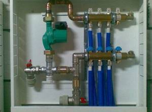
Assembly of the finished kit
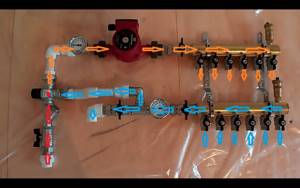
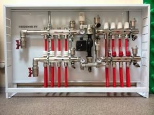
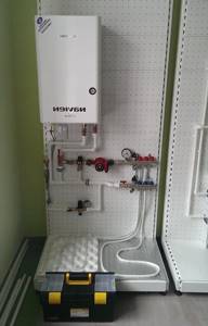
The simplest and most reliable way, but more expensive, is to buy a ready-made set of pumping and mixing unit and manifold group. The assembly manual for the factory kit contains step-by-step instructions, allowing even an inexperienced craftsman to assemble it with his own hands.
Assembling a complete set of pumping and mixing unit and manifold group
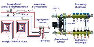
The connection of underfloor heating pipes to the collector is made taking into account the throughput of the distribution combs and a drawn up diagram indicating the sizes of the pipes, their connection points with the elements of the heating system and the places of installation. Work on connecting the water circuit is carried out after installing the collector and protection system (bypass, air valve).
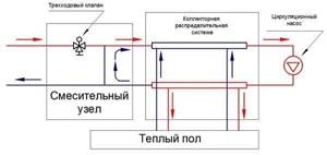
The role of the collector in underfloor heating systems
The collector is an element that underfloor heating cannot do without; all pipelines from the heating circuits are connected to it. Since the temperature of the coolant supplied to the network from the boiler room is too high for the operation of heated floors, a mixing unit always operates together with the collector, ensuring the water temperature is within 40-45 ºС.
Mixing units and manifolds for heated floors perform the task of preparing the coolant at the required temperature and supplying it to all circuits.
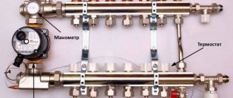
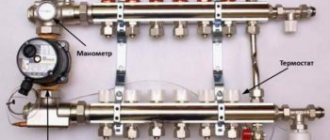
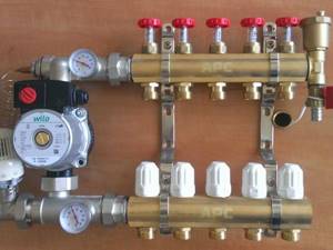
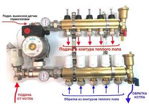
To understand how the entire assembly works, let’s look at the collector device in more detail. It consists of two horizontal tubes connected to the supply and return lines. The manifold body and parts are made of the following materials:
On the supply tube there are branches with thermostatic valves (actuators), and on the return there are branches with flow sensors. There are plastic caps on top of the thermostats for manual adjustment; twisting them leads to pressing on the rod and blocking the flow. Flow meters or flow sensors located on the return pipe of the manifold for a warm water floor serve to visually monitor the amount of water flowing and perform hydraulic balancing of the system.
The cheapest versions of collectors may not have flow sensors.
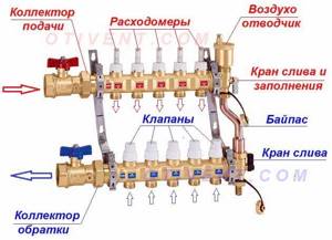
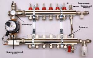
In order to control pressure and temperature, a thermometer with a pressure gauge is installed on the manifold, and a special valve is installed to bleed air. The kit also includes plugs, bends, taps and brackets for attaching the unit to the wall or to the metal slats of the cabinet. Many suppliers practice a complete set of the entire assembly, where there is a distribution manifold assembled with a pump and a two-way or three-way valve.
Advantages of a collector circuit for underfloor heating
Collector piping diagram.
A warm floor with a collector system has a fairly large number of advantages. The main ones are the following:
- Hygiene. Warm floors of this type can be easily cleaned and disinfected.
- Safety. Residents often forget about the high temperature of the equipment used for heating. When using such a design, burns and various injuries are excluded.
- Comfort. The collector device will create invisible coziness and an increased level of comfort.
- Economical. Energy savings, compared to using heating radiators, can reach 50%.
- Long service period. In the collector device, the only element that can wear out is the pipe. The service life of such an element is 50 years.
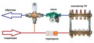
Operating principle
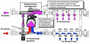
The unit works like this: the coolant circulates through all underfloor heating circuits, driven by a pump.
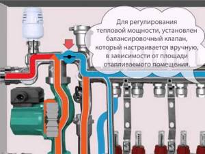
The flow rate in each circuit is controlled by a valve manually or automatically, by a capillary or servo drive. When the temperature in the supply or return pipeline (depending on the circuit) drops below the set value, a two- or three-way valve begins to mix hot water from the system, and the coolant from the return flows into the general network. The figure shows a diagram of the operation of a manifold with an attached water temperature sensor and a two-way valve:
There are several operating schemes for the mixing unit, they use different parts, but its task remains the same: to maintain the required temperature in the underfloor heating system and control the coolant flow in the supply branches.
What is a collector unit in heating
The manifold is a unit of plastic (rarely metal) pipes, valves, pressure gauges, valves, fittings and other auxiliary components. The collector is designed to mix coolant coming from different heating circuits and further distribute them throughout them. As a result of mixing, the temperature of the liquid is equalized, and accordingly, the temperature in the heated rooms remains constant and stable.

The quality of operation of the underfloor heating system depends on the correct assembly of the collector.
The principle of operation of any heating system is known - the heated coolant, after passing through all circuits and pipes, cools down, and under the action of a circulation pump or natural circulation again enters the collector, where it is mixed through the return pipe (return). The proportions of heated and cooled coolant are regulated by special valves, its temperature is controlled by thermal sensors, weather sensors and pressure sensors. If the heating system is too long or the layout of the house does not allow for natural circulation, then a circular pump is connected to the collector.
Usually in an apartment or house, radiators and sometimes homemade registers are connected to the boiler. In any case, the temperature of the coolant in the radiators should be in the range of 70-950C. When connecting a “warm floor” system, which is often done in modern apartments, the coolant temperature should not exceed 30-550C. According to sanitary standards, the maximum temperature of a heated floor should be no more than 300 C, otherwise the decorative floor covering (linoleum, MDF, PVC tiles) will warp, the air in the room will be dry, and walking on a hot surface will not be very comfortable.
Therefore, in such cases, a collector is included in the system - after all, the temperature difference in the central heating system and in the “warm floor” system is significant, and the boiler produces only one temperature value. Another reason for installing a collector is that the heated floor has a large length of pipes. Consequently, the overall pressure in the system will drop. To maintain the pressure at the required level, it is necessary to install a circulation pump, which is included in the design of the manifold.
Recommendations for manifold assembly
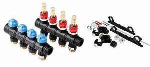
It is not difficult to assemble the underfloor heating manifold, supplied as a complete set.
The tubes for the supply and return coolant are already equipped with valves and flow sensors; they only need to be twisted together if the manifold included is divided into sections of 2 or 3 branches. Then, for the convenience of further assembly, it is better to fix the tubes on standard brackets, then the distributor will be a single unit. Then plugs, connection elements, shut-off valves and control devices are installed.
The delivery set of each product includes instructions, with its help you should assemble and install the underfloor heating manifold.
The next step is to attach the collector to the wall, and after that you can install the circulation pump and valve.
There is no point in doing this in reverse order; then it will be inconvenient to attach the entire assembly. The pump and valve with a thermal head or servo drive are mounted in accordance with the selected diagram, after which the main heating pipes coming from the boiler are connected to them, and pipes from the heating circuits are connected to the outlets. There are situations when the distributor is installed not in the boiler room, but in a corridor or other room, then for installation it is better to use a decorative cabinet for the manifold.
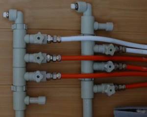
Since the cost of a factory-made manifold is quite high, such a unit can be made independently. True, you will still have to purchase a pump and valve for the mixing part, as well as shut-off valves. The most popular way to assemble a homemade manifold is to solder it from polypropylene pipes and fittings.
This will require sections of PPR pipe with a diameter of 25 or 32 mm, tees and bends of the same size and valves. The number of fittings and valves depends on the number of heating circuits. Tools you will need are a soldering iron for polypropylene pipes with nozzles, scissors and a tape measure.
Before making a polypropylene manifold, you need to measure and cut sections of the pipe so that after connecting the tees are as close to each other as possible, otherwise the assembly will not look aesthetically pleasing.
Then taps and transitions are welded to the tees, and the remaining fittings for connection to the pump are welded to the resulting manifold.
It should be noted that a homemade manifold for heated floors, made with your own hands, will have some disadvantages.
For example, there are no thermostatic valves on the branches in the supply line, and there are no flow sensors on the return line. In their absence, the system will have to be adjusted manually, and this does not always give good results. Of course, all these elements can be installed and connected separately, but then the labor costs will be such that it is easier to purchase a finished product made of plastic, whose cost is quite affordable.
Despite the apparent complexity of the mixing and distribution unit, assembling it is not that difficult. The product usually comes with detailed instructions and should be followed. It is more difficult to make a distributor with your own hands, but this is always advisable, since you still need to buy components, and there will also be difficulties in setting up the manifold.
DIY collector
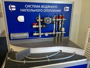
Warm floors have long been a sign of high-standard rooms.
Their use is due to the high quality of heating - the room is heated throughout the entire volume due to natural convection, since the entire floor area serves as a heater for the air in the room.
The floor itself is heated by an electric, film or good old water heater - a hot water boiler.
Tips for installing a manifold for heated floors
Types of collectors.
You can install a similar structure for a heated floor yourself. The distribution manifold is in most cases located in a manifold cabinet or a separate room, which is hidden in the wall. When installing the structure, you should consider the following nuances:
- You should try to place the distribution manifold at the highest point of the heating system in relation to the level of the placed loops. This is necessary so that, if necessary, air can be removed from the installed pipes.
- The distribution manifold should be located in the central part of the premises that are heated.
- You will need to connect circuits of the same length to one structure. If no such contours are available, the length should be as close as possible to the length of the element that is placed nearby.
Function performed
A residential building or apartment has several rooms, and in each of them a thermal circuit is laid in the floor.
It is connected to the coolant main through an input-output unit in the form of two pipes.
The need for thermal energy for each circuit is usually different: the temperature in different rooms may differ. On the other hand, the areas of the rooms are not the same, which means the volume of coolant for each room is also different.
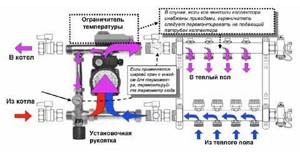
Thus, a distributor with regulator functions must be installed between the boiler and the heating circuits. Such a device is called a collector. In terms of its functionality, it is a mixing unit. Its task is to ensure the supply of water to the circuits.
Specialist's note: the inlet temperature from the boiler can reach 80 degrees, and for a heated floor circuit, according to the standards, the water temperature should not exceed 40 degrees.
You can achieve the required value, i.e. reduce it to 40C, by mixing hot water with cooled return water.
Typically, the collector pipe has connecting nodes - according to the number of thermal circuits.
In total, the collector contains two pipes:
Hot water from the boiler is added to the mixer by turning on a thermostatic valve, which is placed in the path of water supply to the mixer. When the temperature in the mixer drops below the permissible level (we remember - this is 40°C), the valve supplies a portion of hot water.
Please note: a thermostat is installed at each outlet of the mixer comb to limit the volume of hot water for each heated floor circuit.
This group of bimetallic valves changes the flow area, as well as the volume of water passed through.
This allows you to set the temperature as desired. Flow sensors are installed at the return inlets, and the return comb is also equipped with an air vent. The coolant is pumped through the system using a water pump, which creates the necessary pressure in the line.
A complete set of manifold parts also contains various plumbing fittings. In the set of devices for warm water floors, the collector is perhaps the most important of them, as it provides:
Devices for creating a collector unit
A typical standard distribution unit includes devices for efficient operation:
- Mixing valve to set the temperature of warm water;
- Pump to increase the pressure in the system;
- Balancing and locking valves;
- Manifold for inlet and outlet;
- Thermoregulatory device with control sensor;
- Pressure gauges for determining network pressure;
- Devices for removing air bubbles from the heating system;
- Connecting elements for various pipe diameters.
Features of two way valve
In a heating system, a thermal device controls the incoming coolant into each specific circuit according to a given program. If the indicator does not correspond to the parameters, the valve closes and the supply of warm liquid stops.
As the water in the system cools, more warm liquid is supplied through the valve. Water is supplied through the check valve in a constant mode; only the supply at the supply inlet changes.
Due to the low valve speed, it dispenses water smoothly without sudden surges in activity. Two-way valves are the most common in heating systems, but the limitation for their installation is the area of the house, which should not exceed 200 square meters.
Globe valves become clogged and need to be removed for cleaning, so it is recommended not to weld them, but to connect them to the system using a split coupling.
Three way valve action
The operation of the valve differs in that it mixes water from the return and direct supply in the bypass inside itself. Using a perpendicular partition located inside the valve, the supply of warm water from two pipes is regulated, thus changing the water temperature to the specified parameters.
Such a valve is recognized as universal; its use is justified when installed in heating systems with complex circuits and the presence of a large number of circuits, the operation of which is automatically regulated.
Valve operation can result in sudden temperature changes if warm or cold water enters the mixing cavity. The throughput of the device is high, and even a slight cranking of the tap can lead to a change in the temperature regime in the system.
Three-way valves are often combined with actuators to match the heating temperature to the outside air.
Weather sensors
If there is a sharp cold snap outside, then the water in the system will cool faster. Meteorological sensors connected to the underfloor heating system signal the need to increase heating and the temperature of the energy carrier increases.
also manually tighten the valve , but this is difficult to do; it is better to trust the electronics, which check the compliance status every minute and change the position of the valve in the desired range. They also install sensors that reduce the water supply to the system if residents are not at home.
By making a collector with your own hands, you will purchase a device that is completely suitable for individual heating of this particular house. And it will save a lot of money.
Homemade designs
The collector has a significant drawback - high cost.
Therefore, many “homemade” people assemble various options for collectors with their own hands, depending on their wallet and the availability of components.
There are two options for this path:
The 3-loop collector circuit can be implemented as follows:
First, you should assemble the collector pipes - return and coolant supplying the heating circuits. To do this, use one comb for 3 channels or 3 single-loop units for each manifold. The return manifold is equipped with a flow sensor or flow meter and a counter-mounted connection unit for return supply hoses along each loop.
Single-loop manifolds are connected by threaded elements into a comb. Each coolant loop contains a heat sensor with an actuator and a connection point for the power line of the thermal circuit. Air vents are connected to one end of the collectors, and at the other, a coolant pump is connected to the collector pipes, and in addition a thermostatic valve or servo drive is connected to this point, which from time to time replenishes the mixer with hot water. The collector assembly is attached to the wall, checked for functionality and connected to the thermal circuits. After this, final installation and configuration of the entire system is carried out.
Here is the simplest working version of a manifold for heated floors, available to a wide range of DIYers. The capabilities of real collectors are often expanded by connecting more complex control and metering systems.
For example, they connect heat meters, additional temperature meters and much more, no matter what - that’s why homemade inventors exist, to “assemble something yourself.”
If a homemade manifold is soldered from polypropylene pipes, then you need to replenish your arsenal of tools with a special soldering iron for welding parts made of this polymer.
When assembled by welding, the size of each single-loop unit increases due to the seams, and if there are more than 3 thermal circuits, then the entire collector becomes bulky and its installation becomes problematic. Otherwise, the design of the plastic manifold and its settings are no different from those described earlier.
Well, now it's time to finish the article. All the material I wanted to share has been reviewed. I hope it will be useful to you, and you will use it if you need to install a manifold for a heated floor with your own hands. Improve your own practical skills and gain new knowledge, as they say: “It’s never too late to learn!” That's all, thank you for your attention, successful and easy repair!
How to assemble a collector with your own hands
It is impossible to directly connect a heated floor to the boiler with your own hands. For this you need a manifold with valves. It is installed in a cabinet, and the piping begins from there. The collector is provided with access to only one person who will service the system.
The range of collectors in stores is quite large, but it is often difficult to choose the right one for your heating system. In addition, a switchgear is needed on each floor of a private house, which leads to a significant increase in costs. A homemade manifold for heated floors is the right solution, allowing you to save a significant amount of money.
Connection
Since the heating system has a supply and return branch, the collector must consist of two combs connected to them. At the joints, branches are installed to drain water and remove air from the pipes.
The collector is assembled according to the number of connected loops. At each outlet, located at the top or bottom of the comb, taps are installed to ensure that individual circuits are turned off while the rest of the heating is running. It is recommended to make the distance between them 10-20 cm.
Manifold manufacturing
Before assembling a manifold for a heated floor, you need to understand the purpose of each element. It is recommended to make combs with your own hands from a square pipe. Round threaded pipes are welded to them for connection to the boiler and to the circuits. To do this, markings are first made, then holes are drilled, and then the pipes are attached. All joints are thoroughly scalded. A plug is made at one of the ends.
The scale is knocked off, the collector is cleaned and painted with oil compounds. In Fig. Below is a simple 3 loop manifold. The comb and coolant supply pipes from the boiler are painted red, and the return pipes, through which cooled water is supplied to heating, are blue.
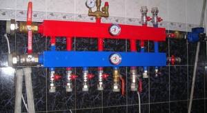
DIY distribution manifold
Air vents are connected to the top of the combs, and plugs are installed at the bottom to discharge sludge. Each circuit can be closed with valves, which also serve to regulate temperature and pressure.
The distribution manifold is designed to control a small system that serves as additional heating. It will be much more complex if used for the main heating system in a large house. Assembling a manifold from polypropylene pipes is much simpler, but the simplest models are made this way.
DIY collector made of polypropylene pipes
Assembly of the collector unit
The underfloor heating manifold contains devices that ensure efficient operation of the system. Each circuit must have control valves. For a complex system, it is advisable to install automatic control valves.
Usually they operate in constant mode, the coolant flow changes only at the main supply inlet. For house areas up to 200 m², two-way valves are used. Their advantage is smooth adjustment. Valves often become clogged. Therefore, they are installed on detachable couplings (“American”) so that they can be removed for cleaning.
A more complex device is the three-way valve. It ensures mixing of forward and reverse water flows, maintaining the specified temperature at the outlet. Inside it there is a movable partition that regulates the flow of water from two inlet pipes. The device is used in all complex systems with automatic control of a large number of circuits. Its advantage is its significant throughput.
With the slightest turn of the tap, the temperature regime of the system changes. The adjustment can be manual or automatic. A three-way valve is often combined with a servo drive operating from an outdoor air temperature sensor. When the weather changes, the temperature in the rooms is maintained constant. As soon as cooling occurs, a signal from the weather sensor enters the control unit and the coolant temperature rises.
If the heated floor serves as the main heater of the house, the temperature of the coolant in the boiler can be maintained lower, which reduces the load on all equipment.
Features of some structural elements
The collector assembly can be installed very quickly, but it must contain some mandatory elements in its design:
- Flow regulator. It must be installed if your system has several circuits. In this case, the length of the pipes may be different. If it is not installed, the heat distribution will be uneven. In this case, adjusting the flow rate makes it possible to balance the supply of heated liquid to each circuit.
- Thermostatic regulators. They help the system respond in a timely manner to temperature fluctuations in the event of room ventilation or changing weather conditions. Such regulators must be installed on each circuit. Room thermostats are used to control temperature.
- Mixing unit. It should be borne in mind that if your heated floor is powered from a general heating system, then the initial temperature of the coolant can reach 70-90 degrees Celsius. It is only acceptable for radiators or batteries. To reduce the coolant temperature, special mixing units are used. Thanks to them, cold and hot liquid are mixed.
- Mixing valve. It is he who is responsible for cooling the too hot liquid. The valves can be adjusted manually or using a special automatic device.
Is it worth making a collector yourself - conclusions
If you want to connect 3-4 floor circuits on a budget basis, then it’s definitely worth the hassle with polypropylene. Provided that the comb is planned to be placed in the boiler room, and not inside a beautiful cabinet somewhere in the corridor. Soldering must be done very carefully so that after 1-2 years your product does not leak.
When it is necessary to assemble a manifold for 8-10 underfloor heating circuits, use fittings made of high-quality brass. Of course, in terms of dimensions, such a product will be larger than the factory one, but it will allow you to save on the number of parts.
Source
How to save money on a mixing unit
Many master plumbers consider it an integral part of the underfloor heating manifold, although these are 2 different elements that perform separate functions. The task of the comb is to distribute the coolant along the circuits, and the mixing unit is to limit its temperature to 35-45 °C, maximum 55 °C. The collector connection diagram shown below works according to the following algorithm:
Note. If the manifold thermostats are controlled by servos, a bypass and bypass valve is added to the mixing assembly. The goal is to organize circulation in a small circle when the servos, for some reason, suddenly block all the circuits.
Good news for those who are very limited in funds, but want to heat themselves with warm floors: installing a two- or three-way valve with a pump is not always necessary. There are two ways to reduce the cost of the system by avoiding the purchase of a mixer:
Let us immediately note that the first option contradicts all the canons and cannot be considered correct, although it is applied quite successfully. The bottom line is this: high-tech wall-mounted gas boilers can maintain the temperature of the supplied water at 40-50 °C, which is acceptable for heated floors. But there are 3 negative points:
Advice. To avoid discomfort from the heat during transitional periods, you need to install traditional heating radiators in the rooms of a private house, and connect underfloor heating when it gets very cold.
Thermostatic heads of the RTL type operate on the principle of a two-way valve, only they are located on each circuit and are not equipped with remote sensors. A thermoelement that responds to changes in water temperature is located inside the head and blocks the flow along the circuit when it has heated up above 45-55 ° C (depending on the adjustment). In this case, the comb is connected directly to a heat source running on any type of fuel - wood, diesel or pellets.
Important condition. For normal operation of heated floors controlled by RTL thermal heads, the length of each circuit should not exceed 60 m. More details about the design of such heating and the correct collector assembly diagrams are described in a separate instruction and in the next video: