Autonomous heating systems can be built in different ways. One of the most popular types of heating systems in the home is the liquid-cooled design. Usually, water with special additives is used as it.
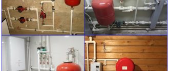
Heating distribution manifold
Such a system may have several heating circuits, for example, heating through radiators and through heated floors. In order for the water to be distributed evenly in such a system, a distribution heating manifold is needed.
Purpose of the heating manifold
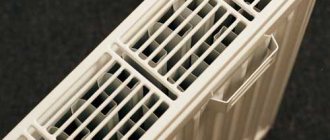
The absence of a distribution manifold in a water heating system can lead to the fact that water may flow unevenly into different circuits of the system. As a result, you will have a hot floor and cold radiators, or vice versa.
This may occur because several heating system circuits can be connected to one boiler outlet. The liquid flows unevenly through such connections, as a result of which part of the premises will not have enough heat. But the efficiency of the heat supply system depends on the amount of coolant passing through the pipes, the volume and speed of its movement.
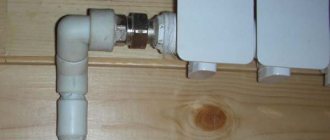
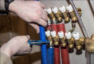
pipes coming from the boiler
Some home owners try to solve this problem by installing additional pumps and control valves. But this only complicates the system and does not always lead to uniform distribution of the coolant.
How is the coolant distributed in a private house?
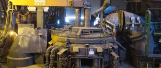
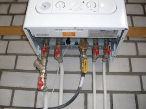
Let’s take, for example, a heating system for a private house with an area of 100 square meters. The device for heating water will be a wall-mounted gas boiler with one outlet pipe with a diameter of ¾ inches.
In our house we have two heating circuits and one circuit that heats water for domestic use with indirect heating. All circuits are built from pipes with a diameter of 1 inch. How to calculate and build an effective heat supply system?
First of all, we understand that the main reason for poor-quality heat supply is an elementary lack of coolant in the system. But the main reason for this shortage is excessively narrow distribution pipelines.
Thus, you can increase the efficiency of the thermal system, that is, increase the diameter of the distribution pipes in two ways:
heat flow distribution
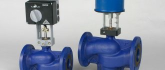
- When using boilers with built-in pumps, a hydraulic arrow (flow distributor) is connected to them. In this case, each heat consumption circuit must have its own circulation pump. But such a device will only work in a small building. As the heated area increases, its efficiency and reliability drops sharply.
- The most reliable way is to connect a water distribution manifold to the heat source.
The most advanced type of distribution manifold is called camplanar. With its help, the problem of connecting pipes of different diameters and volumes of placed coolant is effectively solved.
distribution hydraulic manifold for 4 circuits
Let's look at how to create heat flow distribution systems with your own hands.
Factory manifold assembly
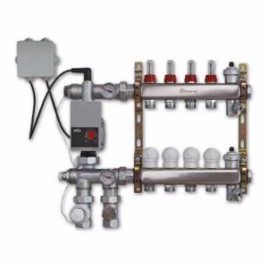
Let's first look at a specific example of what a ready-made distribution unit from the manufacturer consists of.
Table 1. Factory manifold assembly.
| Steps, photo | A comment |
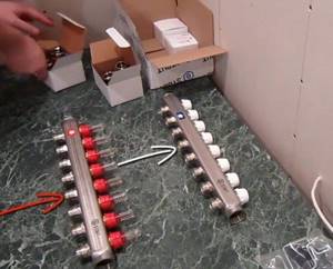
| This collector assembly is called ready-made only because all the necessary elements, selected according to optimal parameters, have already been assembled. It itself is in a disassembled state, and all the parts still have to be put together. |
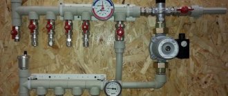
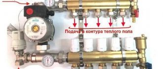
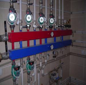
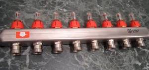
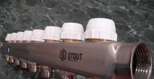
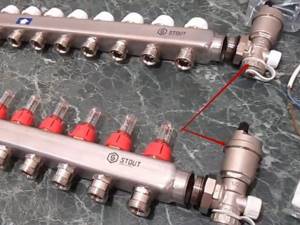
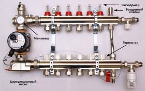
| This is a feed comb, each output of which is equipped with a flow meter (red device on top). Through it, the temperature range in the circuits is set. It is on this comb that, if necessary, the coolant supply to the circuits is shut off. |
| The return comb, unlike the feed comb, is equipped with push-action thermostatic shut-off valves. They are covered on top with caps, on the front side of which the direction of rotation (plus and minus) is indicated, by turning which you can adjust the feed manually. |
| Instead of a cap, you can install a servo drive on the valve, which will automatically regulate water flows. These devices are not included in the kit, but are purchased separately. |
| The desired temperature is set on the thermostat, and it already sends a signal to the servo drive. |
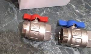
| The heating system is turned off using taps. |
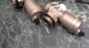
| At the end of each collector, units are installed through which you can drain water from the system or bleed air. |
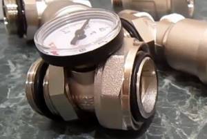
| We think there is no need to explain the purpose of the thermometer. |
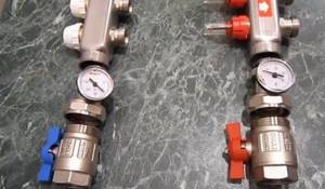
| On the left side of the supply comb there is a hole through which heated water flows from the boiler. First, a tee with a thermometer is screwed onto it, and then a ball valve, through which the connection to the pipeline will be made. The same is done on the return line. |
| To the right, drain units are screwed onto both combs. |
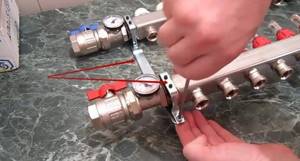
| The manifold assembly kit includes a bracket, through which both combs are tied together and then hung on the wall. |
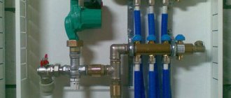
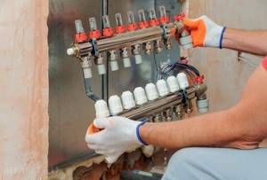
| The assembled unit is attached to the wall or installed in a special cabinet. |
| All that remains is to connect the supply pipeline and circuits to the manifold. |


Video - Manifold for underfloor heating and heating. Review, assembly and installation of the STOUT manifold block
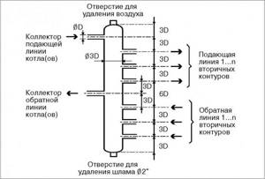
Hydraulic boom and its function
This is a fairly simple device. It can be made from a piece of pipe with a cross-section three times larger than the boiler outlet pipe. It is necessary to weld curved plugs onto the ends of the segment. The plugs are then tapped with threaded holes. They will serve to vent air or drain water. We drill holes in the body of the pipe, in which we also cut threads. We will connect the boiler outlet pipe and heating circuits to them. The body of the hydraulic arrow must then be sanded and painted.
hydraulic arrow
Compalar distribution manifold
Despite the fact that hardware stores have a large assortment of distribution manifolds of different sizes, it can sometimes be difficult to select a device exactly for your heating system. Either the number of contours or their cross-section may not match. As a result, you will have to make a monster from several collectors, which will clearly not have the best effect on the efficiency of the heating system. And such pleasure will not be cheap.
At the same time, you should not believe the stories of “experienced” people that the system can work perfectly even with a direct connection to the boiler. This is mistake. If your heating system has more than three circuits, then installing a distribution manifold is not a whim, but a necessity.
But if there is no distribution manifold on sale that suits your parameters, you can easily make it yourself.
Design
The collector heating system of a private house is capable of ensuring uniform heat distribution and constant temperature conditions in the room, and, consequently, comfort and coziness. Together with a room thermostat, the manifold can guarantee precise flow control.
Remember that in systems where there is a do-it-yourself heating collector, the presence of a circulation pump is a prerequisite. Thanks to its operation, the temperature difference between the coolant at the inlet and outlet of the system is reduced, which means that the heating will be of better quality.
Before making a heating comb, you must study all the necessary information about the components of the system.
Each of the collector outlets must have a ball valve; due to this device, heating devices will be cut off without affecting the system. This kind of system can be equipped for a horizontal one-pipe or two-pipe system.
Manifold for heating system
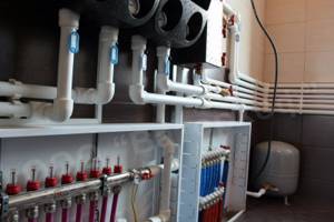
Supply and return manifolds are located on each floor of the main riser. From the collectors, pipes are installed in the floor or walls, and then connected to each heating radiator. If the supply and return pipes are located in the floor screed, each heating device must be equipped with an air valve or air vent.
Heating distribution manifold
Making a distribution manifold with your own hands
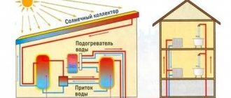
The distribution manifold design is developed based on the number of heating circuits in your system. Assess where your heating boiler is located, what inlet and outlet pipes it has, how many heating circuits or indirect heating circuits will be used in the heating system. Perhaps you are planning to increase the number of circuits in your home, for example adding another room next year. Solar collectors, heat pumps and other devices can also be connected to the distribution system. We also consider all heat distribution systems, including warm water floors, heating radiators, fan coil units, and so on.
We are drawing up a diagram of our heating system, taking into account that each circuit has a hot water supply pipe and a return pipe.
When designing the system, do not forget to determine the location of additional equipment, such as an expansion tank, an automatic make-up valve, a drain and fill valve, a group of thermostats, and so on.
Performs spatial design, that is, we determine where and where pipes will be connected to our distribution manifold. Practice suggests that pipes for connecting a solid fuel boiler and for indirect heating are usually installed at the ends of the collector. If you have a wall-mounted gas or electric boiler in your system, it fits into the top or also into the end.
Based on the available information, we draw up a drawing of the future distribution manifold. It is convenient to use graph paper for this. The distance between the pipes should not be less than 10 centimeters, but they should not be spaced wider than 20 centimeters either. For one heating circuit, the distance between the supply pipe and the return pipe should not be less than 10 centimeters. It is desirable that groups of pipes of the same circuit be visually distinguished.
Collector design
The figure below shows an example of designing a distribution manifold into which six heating system circuits will be connected.
At the first stage, we draw two rectangles. This is the supply manifold and the return manifold.
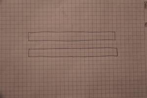
supply manifold and return manifold
We design the connection of the boiler and indirect heating boiler on the manifold trunks. Do not forget to indicate on the drawing the cross-sectional parameters of future pipes.
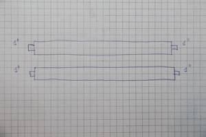
connecting the boiler and indirect heating boiler
We design the connection of heating circuits and additional heating boilers. Don’t forget to indicate the cross-section of the pipes and the dimensions of the pipes. We sign all designed pipes.
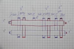
connection of heating circuits and additional heating boilers
At the next stage, we design the connection of additional equipment. In our case, this is an expansion tank, a drain valve, a protective block, and a system thermometer. Please note that the coolant supply circuits are highlighted in red, and the return circuits are highlighted in blue.
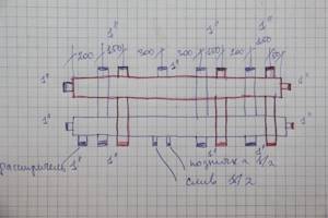
connecting additional equipment
This was a rough drawing. We check its correctness and transfer it completely to a new sheet of paper. It is based on this project that we will create our own distribution manifold.
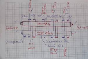
finishing drawing
Operating principle of the heating system
The coolant, be it water or antifreeze, is heated by the boiler, the circulation pump forces it to move to the distribution manifold, or rather, to its fittings, to which the lines leading to heating devices are connected, most often radiators, sometimes heated floors.
Having passed through the heating circuits, the coolant returns through the return lines and, using an electric pump, is supplied to the boiler, where the heating cycle begins again.
In this case, the temperature of the coolant in the circuits is set using a thermostat, which is located on the inlet of the fitting of the supply part of the distribution manifold; each outlet is equipped with a flow meter that regulates the volume of supplied coolant.

The pressure in the lines is controlled by a thermostat, since as the temperature of the coolant changes, the pressure in the circuits changes.
It is worth noting that the pressure in a working system is also affected by air pockets; to eliminate them, the system is equipped with either Mayevsky taps or air vents; in an open heating system, air bubbles escape into the atmosphere through the tank.
We manufacture a distribution manifold
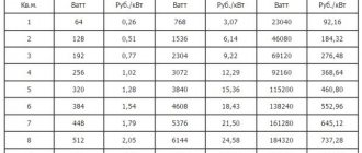
We calculate the material required for the manufacture of the collector. The easiest way to do this is in Excel spreadsheets. At the same time, in this program you can calculate the cost of materials required for the manufacture of the device. We purchase the necessary starting material and prepare tools for self-production.
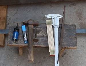
preparing tools
The starting materials for the main parts of the collector will be regular or square pipes. We make the necessary markings on them using calipers, a ruler and a core.
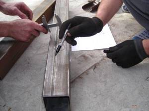
We make the necessary markings
Using a gas cutter, we make holes for the pipes.
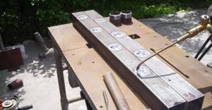
make holes for pipes
We insert the pipes (pipe sections with threads) into the seats.
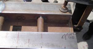
Insert the pipes
We fix the pipes by welding. First, rough it out, and then scald it around the entire perimeter.
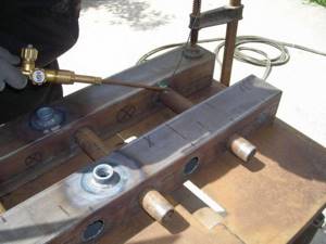
We fix the pipes by welding
We also weld brackets to the body for wall mounting.
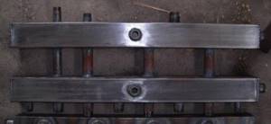
We weld the brackets to the body
We clean the welding areas from scale and rust.
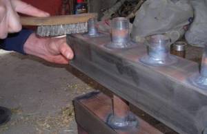
Cleaning the weld areas
We treat the entire structure with a degreasing compound and cover it with paint and varnish.
treated with a degreasing compound, coated with paint and varnish
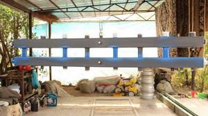
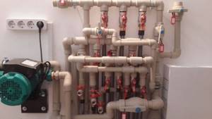
The paint completely sets in two to three days and we have a self-made distribution manifold at our disposal. Now all that remains is to install it in place and connect all the incoming and outgoing circuits to it.
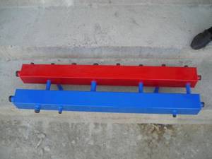
ready-made homemade distribution manifold
A system with a distribution manifold will work much more efficiently than a simple pile of heating pipes
In order to catch all the nuances of making a distribution manifold yourself and the scope of its application, we recommend that you watch the training video.
How to prepare for welding
The easiest way is to weld the device according to the finished drawing. There are many diagrams on the Internet, accompanied by instructions. The drawing is chosen individually; there is no universal welding method; each master provides his own diagrams with recommendations that he considers ideal. After selecting a drawing, the welder decides on the profile material. The following options are common:
- Stainless steel.
- Black steel - it is chosen for its reliability, availability and corrosion resistance.
- Polypropylene. It is an ambiguous material suitable for making a collector, but the finished products are not cheap and are often defective.
The selected material must withstand high temperatures and be resistant to rust. It is difficult to name the best material among those available, since the decisive role is played by the quality of welding and the specific conditions in which the product operates. The operation of the collector is clearly associated with extremely high temperatures; this fact must be kept in mind when purchasing a profile.
The location where the collector is located is studied before the device is manufactured. To make a high-quality collector, you will need to take into account some conditions - the location of the boiler, the distance of the walls from the installation, the power of the entire system. Based on these variables, the master understands what kind of finished product he will ultimately receive. If all parameters are taken into account correctly, the manifold, welded by hand, is made without defects. To improve the result of your work, first consult with a specialist. He will take measurements and tell you what technical nuances are important in this particular case.