What is it and what is it for?
A control valve is one of the types of control fittings, the main function of which, as you can guess from the name, is to regulate the movement of contents in the pipeline. This is done by changing the pressure and flow rate of the medium entering through the through hole of the fittings.
Along with it, a shut-off and control valve is used, which not only has the function of automatically changing the flow rate, but is also capable of completely stopping the flow circulation.
The functions of control and shut-off valves are combined in a shut-off and control valve.
Areas of use and design features
Control valves are used in domestic or industrial gas and water supply systems. They are also installed on main transport pipelines carrying oil and gas. The flow is adjusted by changing the diameter of the passage hole. In this case, the system capacity increases or decreases.
The simplest is the straight-through valve. It contains the following parts:
- a tee body, inside of which there is a passage hole;
- flanges on the pipes (threads may be present in this place);
- seals ensuring the tightness of the device;
- gate;
- rod (a fragment with the help of which the position of the shutter changes).
The cost of the product depends on the material of manufacture, type, size and technical characteristics. The price ranges from 1000−99000 rubles.
Controls and technical characteristics
Manual control has now been replaced by modern methods of controlling control valves, based on the use of various types of drives and combinations of sensors that detect the slightest changes in the state of the pipeline contents.
According to the purpose and conditions of use, the following types of control are used:
- hydraulic;
- electrical;
- electromagnetic.
- pneumatic.
valves are:
- capacity in Kv;
- diameter DN;
- nominal pressure rating;
- working temperature.
The specified characteristics can be found in the technical documentation supplied by the manufacturers to the product. The features inherent in this type of control valves are a quick response to changes in environmental characteristics and reliable tightness.
Connection type
Depending on the type of connection to network pipes, control valves are:
- welded;
- flanged;
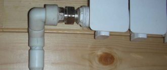
- fitting
- coupling;
- tsapkovymi.
Welded fittings (for welding) are produced only in a steel casing. This type of connection is the most reliable, but has a high execution price and is limited in maintainability. Used in industrial networks.
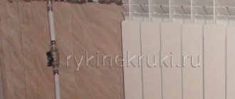
Flange products have found the widest application in all major highways with various environments. In household communications, control valves are connected through threaded connections on couplings.
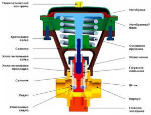
Device
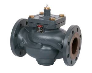
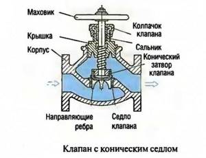
Let us consider, using the example of a flanged single-seat control valve, the design of this type of valve.
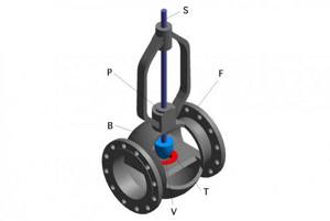
The device consists of a cast body B, in which a passage hole called seat V is placed. A plunger T is lowered into it, fixed on a rod S moving up and down. Flanges F are welded to the body, through which the unit is connected to the pipeline. The sealing unit P serves to seal the entire device.
Principle of operation
The essence of the operation of a control valve is to move a plunger or other type of valve under the pressure of a moving medium. When the shut-off element blocks part of the orifice, the flow of liquid or gas passing through the valve is reduced. Complete closure of the valve causes the flow to be blocked and the pressure in the system to drop to zero.
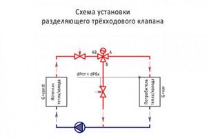
Based on their operating principle, control devices are divided into those that block, mix or separate the flow of the working medium. Shutting valves include two-way valves, and mixing valves include three- and four-way valves.
Design and principle of operation of the control valve
Any pipeline includes in its design devices designed to regulate, turn off and on, and move substances, which are called “fittings”. They all have their own classification, including control valves. This type allows you to maintain pressure, level and flow within the required limits. Let's take a closer look at the main types of control valves and their purpose.
Types of control valves
Due to their design features, control valves are very similar to shut-off valves. Therefore, these elements often have the same brand. Regulating devices are divided into 2 types:
- pressure reducing, which works to reduce the pressure of the working environment;
- shut-off and regulating.
Now about the types of control valves. The most common type is considered to be control valves, which are also divided into several subtypes:
- checkpoints;
- corner;
- mixing systems with a three-way design.
Other types of control devices include shut-off and control valves, direct-acting pressure regulators, and level regulators.
All of the listed devices will be discussed in more detail below.
Features of control valves
Control valves, as mentioned earlier, are among the most common types of shut-off devices. Their main function is to change the pressure of the medium that passes through a certain pipeline system. Scope of application of these devices:
- plumbing systems;
- gas supply systems;
- pipelines designed to transport petroleum products and gaseous substances.
The material used for the manufacture of this fittings can be varied: brass, cast iron, steel, high-alloy alloys. The choice of a specific design depends on the piping system and its environment.
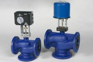
Depending on the operating features, all control valves are divided into 2 types:
- with a manual drive, where control occurs using a specially built-in steering wheel, which, if necessary, must be rotated by hand. For pipes with large parameters, this option is practically not used, since bringing the control device into operation requires considerable effort;
- with automatic control, where work is performed due to the built-in hydraulic, pneumatic or electric drive. To ensure timely operation of the valve, the control device includes sensors that measure the existing pressure in the system.
There is also a classification of control valves depending on their shape:
- pass-throughs are installed on a straight pipeline and do not affect the direction of the medium in any way;
- angular ones change the direction of the medium, and therefore the pipeline itself, by 90˚;
- Mixing systems include 3 pipes in their design, which allow two working media to flow together.
Operating principle of shut-off and control valves
The main purpose of shut-off and control valves is to control the working medium in the pipeline and change its flow. This control valve can be used in the following systems:
- heating and hot water supply networks;
- central and individual heating points;
- ventilation system.
For each condition there is a certain type of execution and material used.
Shut-off and control valves are universal control devices. This is explained by the fact that they not only control the flow of the medium used in the pipeline, but also perform a shut-off function that can completely block the flow.
Let's consider the principle of operation of shut-off and control valves: inside the housing, the shut-off element moves due to the rotation of the rod, which is driven manually or using the provided drive. A special feature of this control device is the presence of a seal, thanks to which when the rod is lowered, the system is completely sealed.
Shut-off and control valves have a number of advantages, the most important of which are ease of use and maintenance, and reliability in operation. Installation of control devices is possible not only on standard-type pipelines, but also on pipelines with non-standard angles and turns. In addition, they are often used to work in aggressive environments.
Direct acting pressure regulators
A direct-acting pressure regulator is necessary to automatically maintain the required pressure drop in one of the sections of the system.
This control valve is divided into 2 types:
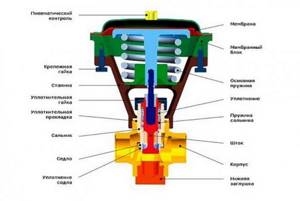
The pressure regulator consists of a body, a double-seat valve, a cover complemented by a stuffing box, a weight mechanism and a membrane-type actuator.
A design feature of such control valves is the presence of two valves on one stem. This feature is necessary to balance the pressure of the working medium on the valve, and accordingly, on the rod.
Both types of regulators differ from each other only in the location of the valves relative to the seats. The control valves “after themselves”, under the influence of pressure from the load mechanism, thanks to the valves, form a passage in the seats. The essence of the operation of this control device is quite simple: when the working medium enters it, the flow section is in the open state, so it passes through it into the pipeline. There, an increase in pressure occurs, which moves along the impulse tube to the membrane and creates a load on the rod in the opposite direction from the influence of the load placed on the lever. When a force greater than the force of the load is achieved, the movement of the rod will be directed downward and the valves will close the holes in the body.
When setting such control valves to a certain pressure indicator, it is necessary to select the size of the load and its location on the lever.
The difference between the principle of operation of control valves “up to itself” and the previous type is in closed valves under the influence of an existing load. When the pressure in the system increases, when it is transmitted through the impulse tube to the membrane, a force is created on the rod in the direction opposite to the action of the load. This leads to the opening of the valves, which subsequently leads to the release of the working environment behind them. This means that the pressure in the system begins to decrease.
Level Control Information
The purpose of the level regulator is to maintain the level of the working medium (liquid) within the required limits and at a given height. The vessel used may be under pressure, or it may be connected directly to the atmosphere, which is much more common. Such conditions are typical for tanks filled with oil products or water. The pressure indicator here is maintained at a given level by introducing an additional volume of liquid. In this case, the control valve is called a power regulator. When liquid is released from a reservoir under excess pressure, the control valve is called an overflow regulator.
The active and main elements in such control valves are a level position sensor, more often called a sensitive element, and an actuating element, presented in the form of a control or shut-off valve.
The operating principle of such a device is based on stopping or regulating the supply of the working medium (liquid) using an actuator, the operation of which depends on the command notification of the built-in sensor.
For direct-acting level controls, the sensor is usually in the form of a hollow spherical float connected to the valve gate. When the water level increases or decreases beyond the established limits, the float creates a lifting force, which moves the valve lever in the direction specified for the operation of the regulator actuator.
Conclusion
Control valves are very important elements present in all pipeline systems. The functions of these control devices include maintaining the pressure in the system at the proper level. Some also additionally perform a locking function. We can endlessly list the different types of control valves, but the most commonly used are control and shut-off valves, direct-acting pressure regulators and level regulators.
Types and designs
Depending on the functions for changing the direction of flow, the devices we are considering are:
- passageways that do not change the direction of the medium; Globe valves are installed in pipeline sections without bends;
- angular, shifting the medium at a right angle;
- mixing, mixing two types of flows with different states into one.
According to their design features, control valves are:
- saddle;
- cellular;
- membrane;
- spool types.
Device classification
Regulators can be classified according to several parameters:
| Characteristic | Types |
| In the direction of flow |
|
| By control method |
|
| By mounting method |
|
What type of valve will be used depends on the scope of its application and the required design features.
Differences
In saddle devices, the locking element is made in the form of a rod, disc or needle plunger. In small cross-section pipes, single-seat fittings are installed; in networks with a diameter of up to 300 mm and a pressure of up to 6.5 MPa, double-seated fittings are installed, which have better tightness and a more balanced plunger.
A feature of cage-type structures is their shutter, made in the form of a cylindrical piston located in the cage. This design reduces noise and vibration when the valve is turned on.
The difference between membrane fittings is the limitations in control methods: their devices are equipped only with pneumatic or hydraulic actuators. The membrane serves as a shutter in them.
In spool valves, the flow level is regulated by turning the valve, that is, the spool, as a result of which the flow hole is partially opened or closed. The mechanism of operation of this fitting is in many ways similar to the operation of an ordinary ball valve.
Types of valves and their principle of operation
The main working part of the control valve is the valve. According to the design of the regulatory body, the following types of valves are distinguished:
- saddle,
- membrane,
- cellular,
- spool valve
Saddle gate
The main elements of a saddle valve are the plunger and the seat. A plunger is a cylindrical piston whose length is significantly greater than its diameter. The seat is a part of the valve located between the passage hole of the valve and its internal part.
As the piston moves through the seat, the size of the bore changes. Single- and double-seat control valves are available. Single seat is used on small diameter pipes.
A double-seat valve allows you to more accurately regulate the pressure in pipes and can be used in pipelines with a diameter of up to 30 cm, since in a double-seat system the plunger is better balanced and it is easier to ensure the tightness of the valve.
Diaphragm valve
This type of valve also has a seat, but instead of a piston, it is covered by a flexible membrane. The membrane not only allows you to regulate the pressure of the working medium, it protects the internal parts of the valve from the effects of aggressive substances. Gates of this type have a high level of tightness of moving elements.
However, a control valve with a diaphragm seal is forced to additionally be equipped with positioners that control the position of the rod. The need to complicate the design is due to a possible decrease in adjustment accuracy due to friction between the elements.
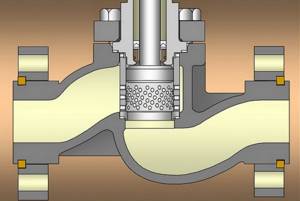
Cage type gate
As a guiding device for a movable element of this type of valve, a cage is used - a saddle with radial holes to control the flow of the working medium.
We recommend that you read: How to make a stepladder (ladder) from a profile pipe
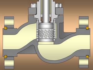
Inside the cell, changing its throughput, a hollow cylinder moves. Thus, the cell performs the function of a saddle and a passage opening.
Advantages and disadvantages
The advantages of control valves that ensure their popularity are:
- the ability to regulate the flow of contents in the pipeline in various ranges, how they differ from devices such as a valve;
- ease of management and operation;
- resistance to various types of working environment;
- possibility of choice depending on the purpose and conditions of use.
The disadvantages include
- the high price of regulators with electric drives and significant costs for monitoring and maintenance;
- overheating of the electric motor during prolonged operation;
- significant hydraulic resistance;
- a certain amount of leakage, in contrast to shut-off devices, allowed by GOST.
Main advantages
- Reliability and durability.
- Simple design solutions.
- Functionality in use.
- Ease of maintenance and repair work.
- Budget prices.
- Versatility of design, etc.
High levels of reliability and durability are determined by the material used. The structures are made from stainless steels with anti-corrosion additives, as well as alloys of brass and cast iron. Products made from alloyed metals are resistant to aggressive chemical compounds and high pressure.
A simple design solution ensures long-term operation, efficient operation of the device while maintaining a balance of working environment indicators.
The valve can be installed on any type of pipe in residential buildings, production workshops, public buildings, and pipelines of oil refinery complexes.
Regulating devices help maintain the required temperature in the room and reduce fuel consumption.
The locking and regulating type of the device helps to simplify the repair process, because ensures shut-off of individual elements of the water supply system or main pipelines.
The functionality of the products ensures high-quality operation when temperatures, pressures or aggressive media pass through.
The device allows you to control the flow in case of accidents or fuel supply failures. Improved mechanisms are equipped with remote sensors.
Tips for choosing
When choosing a control device, be guided by the fact that it should optimally suit your system, meet its parameters and operate for the maximum period.
Use the Internet, study the types and characteristics of suitable devices. Choose a manufacturer with a well-deserved reputation, read reviews of its products on thematic forums.
The main parameters for selecting a device and regulator for heating systems are the nominal diameter DN, the flow characteristic Kvs, the pressure of the working medium, its temperature.
It is important to pay attention to the sealing unit, which can cause a lot of trouble.
Rules for installation and operation of the device
Install the device in accordance with the operating instructions, which must be read before installation.
The device is inspected, foreign particles and debris are removed. When installing, follow the installation direction in accordance with the arrow on the device body.
During operation, the device must be inspected once every six months for general condition and fasteners checked.
Required tools and materials
To work, you will need tools for fastening operations and material depending on the type of device.
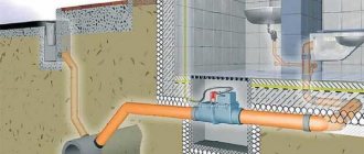
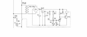
Connection diagram
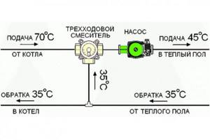
Installation diagram of a three-way control valve:
Work progress
Determine the installation location on the pipeline. It must be accessible for further maintenance of the device.
If a flange connection is made, pay special attention to the inadmissibility of distortions and interference.
Check the correct position of the device body in relation to the direction of flow. After installation, the device is checked for tightness of connections.
Carry out a test run of the valve with the drive, check the operation of the actuator.