Initial information for calculation
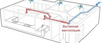
The entire ventilation system is laid out into separate sections and the optimal speed of the air mixture is determined in each of them. The sign by which one area is distinguished from another is the amount of air (flow). If this value remains unchanged, then there is no need to lay out the ventilation pipeline network into sections. The essence of the calculation comes down to the following:
Calculation of air ducts for uniform air distribution.
- Determine the calculated value of the flow velocity.
- Calculate the dimensions of round or rectangular air ducts and compare them with the standardized dimensions according to SNiP.
- If the dimensions differ from the standardized ones, take the nearest standard value in the series and perform calculations in reverse order to determine the actual speed of air flow.
The standard range of diameters in millimeters of round channels is presented in the table:
| 50 | 58 | 63 | 71 | 80 | 90 | 100 | 110 | 125 | 140 | 160 | 180 |
| 200 | 224 | 250 | 280 | 315 | 355 | 400 | 450 | 500 | 560 | 630 | 710 |
| 800 | 900 | 1000 | 1120 | 1250 | 1400 | 1600 | 1800 | 2000 | 2240 | 2500 | 2800 |
The regulatory requirements for rectangular air ducts are somewhat simpler: the ratio of the height and width of the sides of the duct should not be more than 6:3. In practice, this means that it is impossible to produce pipelines that are too narrow with a large width, such as 700x100 mm. Such a channel will have a very high resistance, and during its operation the permissible noise level will be exceeded, since the too wide part will begin to vibrate due to the influence of the air flow on it from the inside. In this case, the ratio will be equal to 7, which does not comply with the standards, but a channel of 600x100 mm with an aspect ratio of 6 is allowed by the standards. But even in this case, the wide side needs to be tightened, especially at high air speeds. To do this, zigs or diagonal bends are made on it with a certain step.
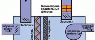
Parameter values in various types of air channels
Modern ventilation systems use installations that include the entire complex for supplying and processing air: cleaning, heating, cooling, humidification, sound absorption. These units are called central air conditioners. The flow rate inside it is regulated by the manufacturer. The fact is that all elements for processing air masses must operate in optimal mode to ensure the required air parameters. Therefore, manufacturers manufacture installation housings of certain sizes for a given range of air flow rates at which all equipment will operate efficiently. Typically, the flow velocity inside a central air conditioner is in the range of 1.5-3 m/s.
Main and branch channels
Main air duct diagram.
Next comes the turn of the main main air duct. It is often long and transits through several rooms before it begins to branch out. The recommended maximum speed of 8 m/s in such channels may not be observed, since laying conditions (especially through ceilings) can significantly limit the space for its installation. For example, at a flow rate of 35,000 m³/h, which is not uncommon in enterprises, and a speed of 8 m/s, the pipe diameter will be 1.25 m, and if it is increased to 13 m/s, the size will become 1000 mm. Such an increase is technically feasible, since modern air ducts made of galvanized steel, manufactured by the spiral-wound method, have high rigidity and density. This eliminates their vibration at high speeds. The noise level from such work is quite low, and against the background sound from operating equipment it can be practically inaudible. Table 2 shows some popular diameters of main air ducts and their throughput at different speeds of air mass movement.
table 2
| Flow, m3/h | Ø400 mm | Ø450 mm | Ø500 mm | Ø560 mm | Ø630 mm | Ø710 mm | Ø800 mm | Ø900 mm | Ø1 m |
| ϑ = 8 m/s | 3617 | 4576 | 5650 | 7087 | 8971 | 11393 | 14469 | 18311 | 22608 |
| ϑ = 9 m/s | 4069 | 5148 | 6357 | 7974 | 10093 | 12877 | 16278 | 20600 | 25434 |
| ϑ = 10 m/s | 4521 | 5720 | 7063 | 8859 | 11214 | 14241 | 18086 | 22888 | 28260 |
| ϑ = 11 m/s | 4974 | 6292 | 7769 | 9745 | 12335 | 15666 | 19895 | 25177 | 31086 |
| ϑ = 12 m/s | 5426 | 6864 | 8476 | 10631 | 13457 | 17090 | 21704 | 27466 | 33912 |
| ϑ = 13 m/s | 5878 | 7436 | 9182 | 11517 | 14578 | 18514 | 23512 | 29755 | 36738 |
Scheme of an ejection ventilation system.
Side branches of air ducts distribute the supply or exhaust of the air mixture to individual rooms. As a rule, a diaphragm or throttle is installed on each of them - a valve to regulate the amount of air. These elements have considerable local resistance, so maintaining a high speed is impractical. However, its value may also be outside the recommended range, so Table 3 shows the throughput of air ducts of the most popular diameters for branches at various speeds.
Table 3
| Flow, m3/h | Ø140 mm | Ø160 mm | Ø180 mm | Ø200 mm | Ø225 mm | Ø250 mm | Ø280 mm | Ø315 mm | Ø355 mm |
| ϑ = 4 m/s | 220 | 288 | 366 | 452 | 572 | 705 | 885 | 1120 | 1424 |
| ϑ = 4.5 m/s | 248 | 323 | 411 | 508 | 643 | 793 | 994 | 1260 | 1601 |
| ϑ = 5 m/s | 275 | 360 | 457 | 565 | 714 | 882 | 1107 | 1400 | 1780 |
| ϑ = 5.5 m/s | 302 | 395 | 503 | 621 | 786 | 968 | 1215 | 1540 | 1957 |
| ϑ = 6 m/s | 330 | 432 | 548 | 678 | 857 | 1058 | 1328 | 1680 | 2136 |
| ϑ = 7 m/s | 385 | 504 | 640 | 791 | 1000 | 1235 | 1550 | 1960 | 2492 |
Not far from the point of connection to the main line, a hatch is installed in the channel; it is needed to measure the flow rate after installation and adjustment of the entire ventilation system.
Indoor channels
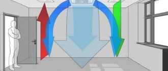
Ventilation air exchange rate.
Distribution channels connect the main branch to devices for supplying or extracting air from the room: grilles, distribution or suction panels, diffusers and other distribution elements. The speeds in these branches can be maintained as in the main branch, if the power of the ventilation unit allows this, or they can be reduced to the recommended ones. In Table 4 you can see the air flow rates at various speeds and channel diameters.
Table 4
| Flow, m3/h | Ø100 mm | Ø112 mm | Ø125 mm | Ø140 mm | Ø160 mm | Ø180 mm | Ø200 mm | Ø225 mm |
| ϑ = 1.5 m/s | 42,4 | 50,7 | 65,8 | 82,6 | 108 | 137 | 169 | 214 |
| ϑ = 2 m/s | 56,5 | 67,7 | 87,8 | 110 | 144 | 183 | 226 | 286 |
| ϑ = 2.5 m/s | 70,6 | 84,6 | 110 | 137 | 180 | 228 | 282 | 357 |
| ϑ = 3 m/s | 84,8 | 101 | 132 | 165 | 216 | 274 | 339 | 429 |
| ϑ = 3.5 m/s | 99,9 | 118 | 153 | 192 | 251 | 320 | 395 | 500 |
| ϑ = 4 m/s | 113 | 135 | 175 | see Table 3 | ||||
The speeds recommended for exhaust and supply grilles, as well as other air distribution devices, must be observed.
The air coming out of them or when being sucked in encounters many small obstacles and produces noise, the level of which must not be exceeded. The sound of the flow coming out of the grate at high speed will definitely be heard. Another unpleasant point: a strong air jet hitting people can lead to illness.
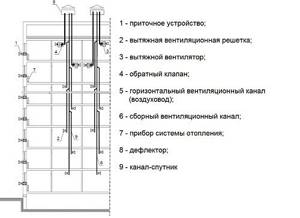
Ventilation systems with natural impulse are usually used in residential and public buildings or in administrative buildings of industrial enterprises. These are various types of exhaust shafts located in the internal partitions of rooms, or external vertical air ducts. The speed of the air flow in them is low, rarely reaching 2-3 m/s in cases where the shaft has a significant height and good traction occurs. When it comes to low flow rates (about 100-200 m³/h), there is no better solution than natural exhaust. Previously and to this day, roof deflectors that operate due to wind load are used in industrial premises. The air speed in such exhaust devices depends on the strength of the wind flow and reaches 1-1.5 m/s.
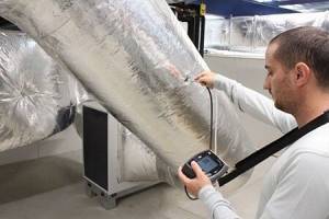
Measuring air flow parameters during system setup
After the supply or exhaust ventilation system is installed, it needs to be adjusted. To do this, using hatches on the air ducts, the flow speed on all lines and branches of the system is measured, after which adjustments are made using throttle valves or air dampers. It is the air speed in the channels that is the determining parameter during setup; through it and the diameter, the flow rate in each section is calculated. The devices used to take these measurements are called anemometers. The devices come in several types and operate on different principles, each type designed to measure a specific range of speeds.
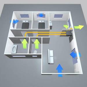
Types of ventilation in a private house.
- Vane-type anemometers are lightweight, easy to use, but have some measurement error. The operating principle is mechanical, the range of measured speeds is from 0.2 to 5 m/s.
- Cup-type devices are also mechanical, but their range of tested speeds is wider, from 1 to 20 m/s.
- Thermal anemometers take readings not only of flow velocity, but also of its temperature. The principle of operation is electrical, from a special sensor introduced into the air flow, the results are displayed on the screen. The device operates from a 220 V network, it takes less time to measure, and its error is low. There are devices that operate on batteries; the ranges of tested speeds can be very different, depending on the type of device and the manufacturer.
The speed of air flow, along with two other parameters, flow rate and channel cross-section, is one of the most important factors in the operation of ventilation systems for any purpose.
This parameter is present at all stages, starting from calculating the air speed in the duct and ending with adjusting the operation of the system after its installation and startup.
Variety of ventilation systems
Currently, the construction industry offers a wide range of ventilation systems designed for any area and purpose of premises. Their main classification is the division into supply and exhaust types. In the first case, air enters the room through air ducts, where its pressure increases. As a result of this process, the air escapes outside through doors, windows and other openings that are located in the room.
The supply system has a complicated mechanism: before the air enters the room, it passes through the air intake grille and valve and ends up in the filter element. After it it is sent to the heater, and then to the fan. And only after this stage it reaches the finish line. This type of ventilation system is suitable for rooms with a small area.
A combined version of supply and exhaust systems is considered the most effective method of ventilation. This is due to the fact that polluted air does not stay in the room for a long time, and at the same time fresh air constantly enters. It is worth noting that the diameter of the air duct and its thickness directly depend on the desired type of ventilation system, as well as the choice of its design (regular or flexible).
Based on the way air masses move in a room, experts distinguish between natural and mechanical ventilation systems. If the building does not use mechanical equipment to supply and purify air, then this type is called natural. In this case, there are often no air ducts. The best option is a mechanical ventilation system, especially when there is no wind outside. This system allows air to move in and out of the room through the use of various fans and filters. Also, using the remote control, you can set comfortable temperature and pressure levels inside the room.
In addition to the above classifications, there are general and local ventilation systems. In production, where it is not possible to remove air from sources of pollution, general ventilation is used. In this way, harmful air masses are constantly replaced by clean ones. If polluted air can be eliminated near the source of its origin, then local ventilation is used, which is most often used in domestic living conditions.
Calculation according to sanitary and hygienic standards
calculation of ventilation of production premises
When using sanitary standards, the area of the entire building . In this case, for each square meter the inflow should be 3 cubic meters. m for an hour.
To obtain the total inflow for this period, which must be ensured, this area must be multiplied by three. Calculation of ventilation of a production room can be carried out using the method described here.
Calculation of the ventilation system
This material was kindly provided by my friend Spirit.
According to sanitary standards, the ventilation system must ensure that the air in the room is replaced in one hour, this means that in one hour a volume of air equal to the volume of the room must enter and be removed from the room. Therefore, the first step is to calculate this volume by multiplying the area of the room by the height of the ceilings. If you have a room with an area of 40 m2 with a ceiling height of 2.5 m, then its volume will be 40 * 2.5 = 100 m3. This means that the capacity of the supply and exhaust systems should be 100 m3/h. This is the minimum consumption, I recommend twice as much. You are looking for a fan with this performance, or better yet even more, because the performance is indicated on the condition that there is no back pressure, and when you put a filter in the supply system, back pressure will appear and reduce the performance. If you have a capacity of 200 m3/h, then in a 125mm pipe the approximate flow velocity will be 4.5 m/s, in a 100mm pipe - 6.5 m/s, and in a 160mm pipe - slightly less than 3 m/s. It is believed that comfortable air speed for humans is up to 2 m/s. If you have an anemometer, then knowing these numbers you can check the performance of the ventilation system.
Next, let’s say you want to install a heater in the supply duct. Using the fourth table you can determine its power. Let’s say it’s -10°C outside, but you want it to be +20°C in the room, which means the temperature difference is 30°C. We find the line 200 m3/h, look at the intersection of the 30°C column, and get a power of 2010 W. It is clear that this is in the absence of other heat sources, so in reality significantly less will be required.
The next point is the calculation of humidity. Warm air holds more water than cold air. Therefore, when heated, its humidity decreases, and when cooled, it increases. Let’s say it’s -10°C outside with 80% humidity, and the air in the room heats up to +20°C. The water content in one cubic meter is 2.1*0.8=1.68 g/m3, and the humidity of the heated air will be 1.68/17.3=0.097, that is, approximately 10%. How much water must be evaporated to obtain a humidity of, say, 50% at a flow rate of 200 m3/h?
Answer: 200*(17.3*0.5-1.68)=1394 g/h=1.4 kg/h
Examples of air exchange volume calculations
calculation of air exchange volume
The following is an example of calculating ventilation based on the exchange rate. For this purpose, we will consider a private house with the following premises:
- kitchen - 19 sq. m;
- living room - 41 sq. m;
- bathroom - 3 sq. m;
- children's room - 14 sq.m. m;
- office - 17 sq. m;
- bedroom - 22 sq. m;
- bathroom - 4 sq. m;
- corridor - 6 sq. m.
The ceiling height in the house is 3 m. To calculate, you need to determine the volume of each room. In this case we get the following values:
- kitchen - 57 cubic meters m;
- living room - 123 cubic meters m;
- bathroom - 9 cubic meters. m;
- children's room - 42 cubic meters. m;
- cabinet - 51 cubic meters m;
- bedroom - 66 cu. m;
- bathroom - 12 cubic meters m;
- corridor - 18 cubic meters m.

Using the table of multiplicity values from the regulatory document, the calculation is carried out in accordance with the above formula:
- kitchen - 57 = 57 (19 sq. m x 3) - rounded to 60;
- living room - 3 x 123 - rounded to 370;
- bathroom - 9 = 9 (3 sq. m x 3) - rounded to 10;
- children's room - 1 x 42 - rounded to 45;
- office - 1 x 51 - rounded to 55;
- bedroom - 1 x 66 - rounded to 70;
- bathroom - 12 = 12 (4 sq. m x 3) - rounded to 15;
- corridor - 18 = 18 (6 sq. m x 3) - rounded to 20;
Technical calculations are free and anonymous =)
- Heating Calculation of heat load based on aggregated indicators MDK 4-05.2004
- Collector diameter calculation
- Calculation of expansion tank for heating
- Calculation of the number of stages of the DHW heat exchanger
- Calculation of DHW heating
- Calculation of the length of compensators for thermal expansion of pipelines
- Calculation of water speed in a pipeline
- Dilution of propylene and ethylene glycol
- Calculation of the diameter of the balancing washer
- Checking the functionality of the elevator heating system
- kg/s to m3/h. Converting the mass flow rate of the medium into volumetric flow.
- Online replacement of Prado radiators with Purmo
- Examples of hydraulic calculations for heating systems
- Sanext Calculation of diameter and settings of Sanext DPV valve
- Calculation of the Sanext heating system floor collector
- Marking RKU Sanext
- Replacing Danfoss AB-QM valve with Sanext DS
- Quick replacement of L and T-shaped tubes with Stabil pipe
- Calculation of gravitational pressure
- Calculation of air conditioner power based on heat flow into the room
- Calculation of resistance in the VK pipeline
- Technical and economic calculation of heat and fuel
- Calculation of the painting area of a metal profile
- Technical unit converter
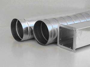
Types and types of air ducts
Before calculating the networks, you need to determine what they will be made of. Nowadays, products made of steel, plastic, fabric, aluminum foil, etc. are used. Air ducts are often made of galvanized or stainless steel; this can be organized even in a small workshop. Such products are easy to install and calculating such ventilation does not cause problems.
In addition, air ducts may vary in appearance. They can be square, rectangular, oval. Each type has its own advantages. Rectangular ones allow you to make ventilation systems of small height or width, while maintaining the required cross-sectional area. Round systems have less material; oval systems combine the pros and cons of other types.
For an example of calculating ventilation, we will select round pipes made of tin. These are products that are used for ventilation of housing, office and retail spaces. We will carry out the calculation using one of the methods that allows us to accurately select the air duct network and find its characteristics.
Subtleties of choosing an air duct
Knowing the results of aerodynamic calculations, you can correctly select the parameters of the air ducts, or more precisely, the diameter of the round sections and the dimensions of the rectangular sections.
In addition, in parallel, you can select a forced air supply device (fan) and determine the pressure loss during the movement of air through the channel.
Knowing the amount of air flow and the speed of its movement, you can determine what cross-section of air ducts will be required.
To do this, take the formula inverse to the formula for calculating air flow: S = L/3600*V.
Using the result, you can calculate the diameter:
D = 1000*√(4*S/π)
Where:
- D is the diameter of the air duct section;
- S – cross-sectional area of air channels (air ducts), (m²);
- π is the number “pi”, a mathematical constant equal to 3.14;.
The resulting number is compared with factory standards approved by GOST, and the products closest in diameter are selected.
If you need to choose rectangular rather than round air ducts, you should determine the length/width of the products instead of the diameter.
When choosing, they are guided by the approximate cross-section, using the principle a*b ≈ S and size tables provided by manufacturers. We remind you that according to the standards, the ratio of width (b) and length (a) should not exceed 1 to 3.
Air ducts with a rectangular or square cross-section have an ergonomic shape, which allows them to be installed flush against walls. This is used when installing home hoods and masking pipes above suspended ceiling structures or above kitchen cabinets (mezzanines)
Generally accepted standards for rectangular channels: minimum dimensions - 100 mm x 150 mm, maximum - 2000 mm x 2000 mm. Round air ducts are good because they have less resistance and, accordingly, have minimal noise levels.
Recently, convenient, safe and lightweight plastic boxes have been produced specifically for indoor use.
Selecting an air handling unit
To select an air handling unit, we will need the values of three parameters: overall performance, heater power and air network resistance. We have already calculated the performance and power of the heater. The network resistance can be found using the Calculator or, for manual calculation, taken equal to the typical value (see section Calculation of network resistance).
To select a suitable model, we need to select ventilation units whose maximum performance is slightly greater than the calculated value. After this, using the ventilation characteristic, we determine the system performance at a given network resistance. If the obtained value is slightly higher than the required performance of the ventilation system, then the selected model is suitable for us.
As an example, let’s check whether a ventilation unit with the ventilation characteristics shown in the figure is suitable for a cottage with an area of 200 m².
The estimated productivity is 450 m³/h. Let us take the network resistance to be 120 Pa. To determine the actual performance, we must draw a horizontal line from the value of 120 Pa, and then draw a vertical line down from the point of its intersection with the graph. The intersection point of this line with the “Performance” axis will give us the desired value - about 480 m³/h, which is slightly more than the calculated value. So this model suits us.
Note that many modern fans have flat ventilation characteristics. This means that possible errors in determining the network resistance have almost no effect on the actual performance of the ventilation system. If in our example we had made a mistake in determining the resistance of the air supply network by 50 Pa (that is, the actual network resistance would not have been 120, but 180 Pa), the system performance would have dropped by only 20 m³/h to 460 m³/h, which had no effect would be the result of our choice.
After choosing an air handling unit (or a fan, if a dial system is used), it may turn out that its actual performance is noticeably higher than the calculated one, and the previous model of the air handling unit is not suitable because its performance is not enough. In this case we have several options:
- Leave everything as is, but the actual ventilation performance will be higher than the calculated one. This will lead to increased energy consumption spent on heating the air during the cold season.
- “Strangle” the ventilation unit using balancing valves, closing them until the air flow in each room drops to the calculated level. This will also lead to excessive energy consumption (although not as much as in the first option), since the fan will work with excess load, overcoming the increased network resistance.
- Do not turn on maximum speed. This will help if the ventilation unit has 5–8 fan speeds (or smooth speed control). However, most budget ventilation units only have step speed control, which most likely will not allow you to accurately select the desired performance.
- Reduce the maximum productivity of the air handling unit exactly to a specified level. This is possible if the automatic ventilation unit allows you to adjust the maximum fan rotation speed.
The importance of air exchange for humans
According to construction and hygiene standards, every residential or industrial facility must be provided with a ventilation system.
Its main purpose is to maintain air balance and create a microclimate favorable for work and rest. This means that in the atmosphere that people breathe, there should not be an excess of heat, moisture, or pollution of various kinds.
Violations in the organization of the ventilation system lead to the development of infectious diseases and diseases of the respiratory system, decreased immunity, and premature spoilage of food.
In an excessively humid and warm environment, pathogenic microorganisms quickly develop, and pockets of mold and mildew appear on walls, ceilings and even furniture.
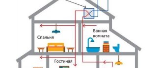
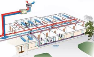
Ventilation diagram in a two-story private house. The ventilation system is equipped with a supply and exhaust energy-saving unit with a heat recuperator, which allows you to reuse the heat of the air removed from the building
One of the conditions for maintaining a healthy air balance is the correct design of the ventilation system. Each part of the air exchange network must be selected based on the volume of the room and the characteristics of the air in it.
Let’s assume that in a small apartment there is sufficiently well-established supply and exhaust ventilation, while in production workshops it is mandatory to install equipment for forced air exchange.
When constructing houses, public institutions, and workshops of enterprises, they are guided by the following principles:
- each room must be provided with a ventilation system;
- it is necessary to observe hygienic air parameters;
- enterprises should install devices that increase and regulate the air exchange rate; in residential premises - air conditioners or fans if there is insufficient ventilation;
- in rooms for different purposes (for example, in patient rooms and an operating room, or in an office and a smoking room), it is necessary to equip different systems.
In order for ventilation to meet the listed conditions, you need to make calculations and select equipment - air supply devices and air ducts.
Also, when installing a ventilation system, it is necessary to choose the correct air intake locations in order to prevent contaminated flows from flowing back into the premises.
In the process of drawing up a ventilation project for a private house, multi-storey residential building or industrial premises, the air volume is calculated and installation locations for ventilation equipment are outlined: water exchange units, air conditioners and air ducts
The efficiency of air exchange depends on the size of the air ducts (including house shafts). Let's find out what the standards for air flow speed in ventilation are, specified in the sanitary documentation.
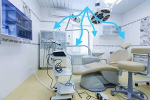
Health care institutions
The air exchange rate in institutions belonging to the healthcare system has the highest values for wards in which inpatient treatment of patients with detected pathologies of infectious (160 m³/h) and non-infectious (80 m³/h) origin is carried out.
According to the standards, most other premises, including doctors’ offices and treatment rooms, must have an exhaust ratio with a natural type of air exchange organization equal to 1-2 units/hour.
A separate point worth mentioning is the organization of the ventilation system for operating rooms. According to modern requirements, they must use a 3-fold air purification system, while operating devices must provide a minimum flow of 1200 m³ of air per hour.
Do I need to rely on SNiP?
In all calculations that we carried out, the recommendations of SNiP and MGSN were used. This regulatory documentation allows you to determine the minimum permissible ventilation performance that ensures a comfortable stay for people in the room. In other words, SNiP requirements are aimed primarily at minimizing the cost of the ventilation system and the costs of its operation, which is important when designing ventilation systems for administrative and public buildings.
In apartments and cottages the situation is different, because you are designing ventilation for yourself, and not for the average resident, and no one forces you to adhere to the recommendations of SNiP. For this reason, system performance can be either higher than the design value (for greater comfort) or lower (to reduce energy consumption and system cost). In addition, everyone’s subjective feeling of comfort is different: for some, 30–40 m³/h per person is enough, but for others, 60 m³/h will not be enough.
However, if you do not know what air exchange you need to feel comfortable, it is better to follow the recommendations of SNiP. Since modern air handling units allow you to adjust the performance from the control panel, you can find a compromise between comfort and savings already during the operation of the ventilation system.
Rules for using measuring devices
When measuring air flow speed and its consumption in a ventilation and air conditioning system, you need to correctly select devices and comply with the following rules for their operation.
This will allow you to obtain accurate results of air duct calculations, as well as create an objective picture of the ventilation system.
In order to record average flow rates, you need to take several measurements. Their number depends on the diameter of the pipe or on the size of the sides if the channel is rectangular in shape
Observe the temperature regime indicated in the device passport. Also monitor the position of the probe sensor. It must always be oriented exactly towards the air flow.
If this rule is not followed, the measurement results will be distorted. The greater the deviation of the sensor from the ideal position, the higher the error will be.
Rules for determining air speed
The speed of air movement is closely related to concepts such as noise level and vibration level in the ventilation system. The air passing through the channels creates a certain noise and pressure, which increases with the number of turns and bends.
The greater the resistance in the pipes, the lower the air speed and the higher the fan performance. Let's consider the norms of associated factors.
No. 1 - sanitary standards for noise levels
The standards specified in SNiP apply to residential (private and apartment buildings), public and industrial premises.
In the table below, you can compare standards for different types of premises, as well as areas adjacent to buildings.
Part of the table from No. 1 SNiP-2-77 from the paragraph “Noise Protection”. The maximum permissible norms related to night time are lower than daytime values, and the norms for adjacent areas are higher than for residential premises
One of the reasons for the increase in accepted standards may be an incorrectly designed air duct system.
Sound pressure levels are presented in another table:
When putting into operation ventilation or other equipment related to ensuring a favorable, healthy microclimate in the room, only short-term excess of the designated noise parameters is allowed
No. 2 - vibration level
The power of the fans is directly related to the level of vibration. The maximum vibration threshold depends on several factors:
- duct sizes;
- quality of gaskets that reduce vibration levels;
- pipe manufacturing material;
- speed of air flow passing through the channels.
The standards that should be followed when choosing ventilation devices and when making calculations regarding air ducts are presented in the following table:
Maximum permissible values of local vibration. If during inspection the actual values are higher than the norms, it means that the air duct system is designed with technical flaws that need to be corrected, or the fan power is too high
The air speed in shafts and channels should not affect the increase in vibration indicators, as well as the associated parameters of sound vibrations.
No. 3 - air exchange rate
Air purification occurs through the air exchange process, which is divided into natural or forced.
In the first case, it is carried out by opening doors, transoms, vents, windows (and is called aeration) or simply by infiltration through cracks at the joints of walls, doors and windows, in the second - with the help of air conditioners and ventilation equipment.
The air in a room, utility room or workshop must be changed several times an hour in order for the degree of air pollution to be acceptable.
The number of shifts is a multiplicity, a value also necessary to determine the air speed in the ventilation ducts.
The multiplicity is calculated using the following formula:
N=V/W
Where:
- N – frequency of air exchange, once every 1 hour;
- V – volume of clean air filling the room in 1 hour, m³/h;
- W – volume of the room, m³.
In order to avoid additional calculations, the average multiplicity indicators are collected in tables.
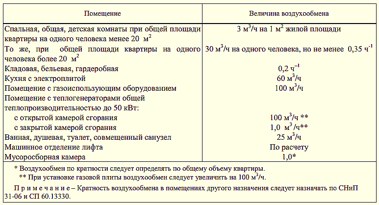
For example, the following air exchange rate table is suitable for residential premises:
Judging by the table, frequent changes of air masses in a room are necessary if it is characterized by high humidity or air temperature - for example, in a kitchen or bathroom. Accordingly, if natural ventilation is insufficient, forced circulation devices are installed in these rooms
What happens if the air exchange rate standards are not met or are met, but to an insufficient extent?
One of two things will happen:
The multiplicity is below normal. Fresh air stops replacing polluted air, as a result of which the concentration of harmful substances in the room increases: bacteria, pathogens, dangerous gases
The amount of oxygen, important for the human respiratory system, decreases, and carbon dioxide, on the contrary, increases. Humidity rises to a maximum, which is fraught with the appearance of mold.
Multiplicity is higher than normal
Occurs if the speed of air movement in the channels exceeds the norm. This negatively affects the temperature: the room simply does not have time to heat up. Excessively dry air provokes diseases of the skin and respiratory system.
In order for the air exchange rate to comply with sanitary standards, ventilation devices should be installed, removed or adjusted, and, if necessary, air ducts should be replaced.
Calculation of supply and exhaust ventilation
Once the fresh air needs and the performance of the ventilation system have been determined, proceed to the air distribution project for the apartment or building. It consists of: an air duct, various shaped products, air distributors (grills) and throttle valves. Before calculating ventilation, you need to draw a diagram of the future air duct in such a way that its length is minimal and its performance is sufficient.
Choose which cross-section of the air duct will be more optimal for you - round or rectangular. The first has a smaller height, which saves ceiling space, while the second is easier to install. It must be taken into account that the air flow speed should be limited to 3-4 meters per second. If it is larger, there will be a lot of noise.
The required design cross-sectional area of the air duct is calculated as follows:
Sc (sectional area) = L (air flow rate) multiplied by 2.778 (a generally accepted coefficient for various dimensions) and divided by V (air flow rate through the duct).
The result will be in square centimeters for greater convenience.
For round air vents it is calculated as follows: S = tt multiplied by D / 400
For rectangular ones, S= A times B/100.
S is the actual area, D is the diameter, A and B are the width and height.
These indicators need to be calculated for each branch of the air duct. For household utility networks, choose round air vents from 100 to 250 mm; if your choice is rectangular products, their diameter should be completely equivalent.
WHAT HIGH SHOULD THE VENTILATION PIPE BE?
1. The height of the ventilation pipe above the roof located next to the chimney must be equal to this pipe.
2. Above a flat roof, the pipe must rise to a height of at least 500 millimeters.
3. If the pipe is located at a distance of no more than one and a half meters from the parapet, or from the ridge, its height above the roof ridge should be more than 500 millimeters.
4. If the pipe is located from the parapet or from the ridge at a distance of 1.5-3 meters, its height should not be lower than the roof ridge.
5. The ventilation pipe, located at a distance of more than three meters from the ridge, must be no lower than a line drawn approximately downward from the ridge of the roof towards the horizon line. This line must be drawn at an angle of 10 degrees.
Some useful tips and notes
As can be understood from the formula (or when carrying out practical calculations on calculators), air speed increases as the pipe size decreases. A number of advantages can be derived from this fact:
- there will be no losses or the need to lay an additional ventilation pipeline to ensure the required air flow if the dimensions of the room do not allow for large ducts;
- it is possible to lay smaller pipelines, which in most cases is simpler and more convenient;
- the smaller the diameter of the channel, the cheaper its cost; the price of additional elements (dampers, valves) will also decrease;
- the smaller size of the pipes expands the installation possibilities; they can be positioned as needed, practically without adjusting to external constraining factors.
However, when laying air ducts of a smaller diameter, it must be remembered that as the air speed increases, the dynamic pressure on the pipe walls increases, and the system resistance also increases, which will require a more powerful fan and additional costs. Therefore, before installation, it is necessary to carefully carry out all calculations so that savings do not result in large costs or even losses, because a building that does not comply with SNiP standards may not be allowed to operate.
METHODS FOR CALCULATING PRESSURE LOSS IN A VENTILATION PIPE
In addition to the height of the pipe, the pressure loss occurring in the duct is also calculated.
Several formulas are used for the calculation: The task of ventilation is to remove old stale air from the room and necessarily replace it with fresh street air. Only adequate ventilation can ensure the creation and maintenance of an atmosphere favorable for the human body in rooms. When thinking about how to calculate ventilation in a room, you need to understand that in addition to its main purpose, it is the key to maintaining dryness for house structures. It is the correct operation of this system that will not allow rot and mold to form on the surface of the walls, even in rooms with high humidity.
Properly designed ventilation is a prerequisite for creating an optimal microclimate in any modern home. Centralized heating, anti-draft equipment, careful thermal insulation - all this requires a scrupulous approach to the design of the ventilation system. The lack of constant air exchange leads to stuffiness. In turn, high levels of moisture in the room lead to condensation.
To calculate ventilation as correctly as possible, we can take as an example natural convection, which works to remove unpleasant odors and air with high humidity from rooms. Natural convection delivers warm air layers from the house to its roof. For such a wire, air duct pipes are used, through which the flows are directed through the ridge ventilation elements and then discharged outside. This type of ventilation is a self-regulating type. There are no fans, eliminating the need to use electricity.
Ventilation in the room must be mandatory. At the same time, modern technical designs, which include air purification from almost all street pollutants, are not as useful as they might seem at first glance. They are able to purify the street air so much that it becomes completely artificial and loses its natural properties and characteristics. That is why choosing a place to live is fundamental to creating a healthy atmosphere in a house or apartment. Clean air outside ensures the presence of clean natural air inside and eliminates the need for powerful air purification devices in ventilation systems.