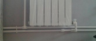
In order for the heating system to function without frustrating failures, there should be no air in it. An impressive amount of oxygen in the coolant can “give rise” to such phenomena as noisy pumps and batteries that do not heat up. No less a disaster is corrosion - the process of destruction of the metals from which pipes and valves are made. To protect the system from destructive processes, a special device is used - a separator. Its task is to collect oxygen “walking” in the water, then remove it from the coolant.
Why do you need an air separator?
A device that can cope with the problem of air locks and other contaminants. Called an air separator. If you do not use this device, air and air pockets in the heating system can cause many problems in the coordinated operation of all elements of the system. First of all, the heat transfer of devices begins to decrease.
The absence of a separator can sooner or later lead to premature wear of pump parts, bearings and blades, which will significantly reduce its efficiency.
If the separator does not work or does not work correctly, the inside surface of radiators, boilers and pipes becomes vulnerable to corrosion. The separator is able to completely remove oxygen from the system, thereby de-airing it. One of the disadvantages of the separator is the creation of resistance to the flow of coolant, which directly has a negative impact on the hydraulics of the heating system.
How does the performance of a heating system without a separator deteriorate?
- Small bubbles stick to the walls of the radiator, which stops giving off heat. Heating efficiency is reduced to a minimum.
- The pump that supplies the water wears out, works inefficiently, or stops working altogether.
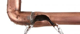
- Oxygen entering valves, pipes and filters leads to metal destruction.
- The consequence of corrosion is the appearance of rust, which moves along with water masses. Rust accumulations form sludge, which causes the heating system to malfunction.
More recently, the fight against the presence of gas in the system happened like this: the system was always kept under some pressure, which made it possible to protect against oxygen suction. To prevent air penetration, special pipes were used. In places where the greatest accumulation of oxygen occurred, air vents were installed.
Multi-stage system
System with air removal devices
To avoid problems with the formation of air jams, even at the design stage of an autonomous heating system, one very important point must be taken into account. It is based on a multi-stage air exhaust system from each group of heating devices separately. In this case, it is necessary to use specific types of air vents in several installation locations. For example:
- To bleed air from the boiler heat exchanger, install an automatic air vent directly on the boiler.
- Each collector has its own local air vent.
- Each radiator is equipped with its own Mayevsky manual tap.
- For risers, special air vents must be used, which must be planned for installation at the highest points.
Air and sludge separator: cleaning and protecting the heating system
In order for the heating system to function without frustrating failures, there should be no air in it.
An impressive amount of oxygen in the coolant can “give rise” to such phenomena as noisy pumps and batteries that do not heat up. No less a disaster is corrosion - the process of destruction of the metals from which pipes and valves are made. To protect the system from destructive processes, a special device is used - a separator. Its task is to collect oxygen “walking” in the water, then remove it from the coolant.
Negative influence of air on the operation of the heating system
It is difficult for an inexperienced person to believe that ordinary air can become a colossal problem.
But we have to admit: oxygen acts on the condition of the heating system like a slow poison on a living creature. Here are just a few examples of system deterioration caused by air:
- Small air bubbles sticking to the walls of the radiator prevent it from giving off heat. The efficiency of the heating “organism” decreases sharply.
- The pump that supplies water wears out faster.
- Oxygen entering pipes, filters, valves and consumers destroys metal.
- Rust, which appears as a result of corrosion, “wanders” along with the masses of water. When it accumulates, it becomes sludge (dirt) and can lead to system malfunction.
Methods for dealing with air in pipes
Until recently, experts fought the presence of gas in pipes in the following ways:
- made sure that the system was constantly under slight pressure (this trick protects against oxygen being sucked in);
- they used special pipes through the walls of which air cannot penetrate;
- In those areas where it is easiest for oxygen to accumulate, air vents were installed.
Experience has shown that the air vent most effectively copes with the task of eliminating oxygen only when it works in tandem with a separator.
Methods for oxygen penetration into the system
Many people, upset by poor heating in their homes and the frequent accumulation of oxygen in the radiator, rush to blame the specialists who design and install heating equipment for these troubles.
It is easier for an inexperienced person to conclude that the elements of the heating system are not of very high quality and are not airtight, than to understand the true reasons for the appearance of gas in the pipes.
Let's name the main ways air gets into the system:
- Oxygen appears in the pipes in the form of microscopic bubbles located in the water column. When the water gets hot, the air “escaps” from it, turning into free gas. And the more the liquid heats up, the more gas will come out of it.
- Air penetrates through connecting elements (gaskets, air vents).
- After repair work, oxygen can literally “burst” into the heating system.
To be honest, it is unrealistic to completely protect heating equipment from oxygen. Even a long downtime of the system leads to the fact that there is too much air in it, and it has to be vented.
To reliably protect pipes, filters and other components of the heating system, an air separator (separator) is required. The use of this compact device helps solve the problem of “air invasion”. This means you will get rid of the sludge that appears due to oxygen activity.
Air vent and separator are not the same thing
We often hear questions about the difference between an air separator and an air vent.
At first glance, these two devices perform the same task - remove oxygen from heating systems. But the air vent removes gases from the system gradually as they accumulate.
The separator acts more decisively. It quickly separates gases dissolved in water and removes them from the heating system.
If you want all elements of the heating system to work smoothly, it is worth installing an air separator. It is important to choose a compact device that would cope with the responsibilities of removing oxygen from the coolant. Over the past few years, flamcovent separators have become extremely popular.
The effectiveness of these devices is enormous, because their work is based on the principle of fusion. The essence of the method: tiny air bubbles, in contact with the surface of the device, stick to it. In a short period of time, the bubbles combine into large “clouds”. Then they break away from the separator and float up.
The Importance of Pall Rings
If you are thinking about purchasing an air separator, you will probably be curious about how flamcovent separators “fish out” even tiny air bubbles from the flow so quickly and efficiently.
Introduction
It is known that when starting heating systems, big problems are caused by air cavities remaining inside and solid particles or sludge circulating in the flow.
The presence of air cavities and plugs automatically means a high concentration of dissolved gases in the water, which can cause increased corrosion and erosion processes, problems with cavitation, and a decrease in the efficiency of pumps, fittings and heat exchangers. The presence of gases, in turn, stimulates the appearance of solid particles in the coolant. By settling in places with the lowest speed, layers of particles sharply reduce the efficiency of heat transfer. Once they get into pumps and control valves, they quickly damage the equipment. Corrosion processes under a layer of deposited sludge are difficult to slow down. Considering that when systems are periodically stopped for maintenance, tons of particles settle at the bottom of pipelines, this process each time creates new sources of pitting corrosion. Currently existing methods and equipment are aimed largely at treating water entering the system /1/
At the same time, it is sometimes not taken into account that systems cannot be perfectly sealed, gas flows into systems can be quite large even in closed systems, and degassing of large and complex systems can take a long time. In this case, as in the case of start-up, problems can arise even if the quality of the make-up water is normal.
It can also be noted that in case of design or configuration errors, areas of negative pressure may appear in some areas of the systems. In this case, conditions are created for the emergence of stable gas flows into the system.
It is generally accepted that in most cases, installing a sufficient number of air vents will ensure degassing of systems during operation. To evaluate the effectiveness of their use, we recall that the gases in the system are in three states: in the form of cavities, bubbles and microbubbles, and in a dissolved state /2/. The work of air vents is mainly related to the first form, because Only the appearance of a significant volume of gas in the upper part of the air vent activates the mechanism for its removal. The bulk of bubbles and microbubbles moving in the flow simply do not have time to rise into the air vent chamber. Therefore, air vents should be located at the highest points of the system, in places of local elevations and on radiators. In complex systems it is necessary to install a large number of these devices. At the same time, the air vent, along with the expansion tank, is one of the most vulnerable elements. Almost all differences in designs and prices are associated with varying degrees of reliability and protection of air vents from blocking them with bubbles or depressurization when dirt particles get inside the trigger mechanism.
In complex systems with a large number of air vents installed in hard-to-reach places, it is difficult to check the quality of their work. The low price (and sometimes quality) of air vents often does not compensate for the complexity of maintenance and losses from problems that arise. Air cavities that are not removed in time can be reabsorbed by water when the operating mode of the system changes, further stimulating corrosion. Water leaking out or air getting inside when the air vent is depressurized can quickly damage any system. Automatic float air vents remove air pockets and bubbles as they appear in automatic mode /3/. Air vents of this type provide better tightness and are better protected from blocking and depressurization when dirt gets into them.
Mud collectors installed inside the system circuit are usually equipped with mesh with large cells. Otherwise, they quickly become clogged and the circulation flow can be completely blocked. Thus, we can assume that inside the system, as a rule, there are no devices that perform processes of fine cleaning of the coolant from sludge and its amount can increase as a result of chemical reactions or detachment of deposits.
Separators for degassing and sludge removal
Fig.1 Separator
The separators that appeared in recent years in the Russian Federation began to be produced in Europe more than 30 years ago and have become a standard element for degassing and removing sludge from heating and water supply systems. In addition to removing plugs, separators remove microbubbles and sludge particles from the water flow and combine the functions of air vents, filters and deaerators. Separators do not require consumables, energy or maintenance, operate for several decades, and have a simple and reliable design without moving parts.
The universal separator is a metal cylinder with an air vent at the top, a sludge discharge valve at the bottom and a stationary mechanical separating element inside (Fig. 1). An element inside the separator ensures rapid transport of microbubbles to the top and deposition of insoluble particles below as the water flow passes through the separator. The separator's automatic float air vent removes air accumulated at the top, and periodic sludge removal is carried out manually using a ball valve at the bottom of the separator. In both cases, the system does not depressurize. When the system is initially filled with water, large air bubbles are quickly removed using a special valve in the air vent housing. Separators are installed vertically.
Separators from different companies, as a rule, differ in different types of separating elements. In Pneumatex separators (Switzerland), such an element uses a petal spiral (spirals) with a profiled surface made of stainless steel, installed vertically along the axis of the separator (Fig. 1). The mechanisms for extracting gases and solid particles may also be different. As a rule, the gravitational mechanism of particle sedimentation and bubble sublimation is used. To enhance the effect, the flow speed inside the separator is reduced (the cross section is increased), and the flow is laminarized. Some models use a centrifugal effect to spin the flow inside the separator. When using working elements with a large area, the mechanism of sorption of microbubbles on the surface is activated with their further merging into larger bubbles and floating up.
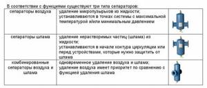
The range of application of separators is quite wide.
For example, Pneumatex industrial separators (standard sizes DN 50 – 600 mm) are capable of processing flows in the range of 5 – 2000 m 3 /h. The housings of industrial separators are made of steel.
Brass separators for small objects (standard sizes DU 20 – 40 mm) process flows up to 5 m 3 /h. All brass separators are assembled from basic elements and can be easily transformed.
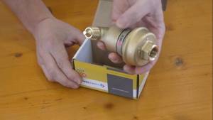
Automatic air vent.
View prices for Automatic air vents
Hide
I would like to say that this particular model is not similar to those air vents that are sold everywhere on construction markets. Of course, it is intended, like its more budget-friendly “relatives,” for only one task - to remove excess air. But its internal design is much better. The ventilation valve mechanism ensures complete absence of water leakage. The special design of the air chamber ensures that dirt particles do not enter the air vent. But the increased volume of this air chamber will prevent significant fluctuations in the existing heating system. And it has a service life of 30 years, unlike all its “brothers” that are sold on the markets and can last you a maximum of 1 year.
But removing air bubbles through an automatic air vent will be much more effective if it is used in a special device - a separator.
Do-it-yourself hydraulic arrow for heating
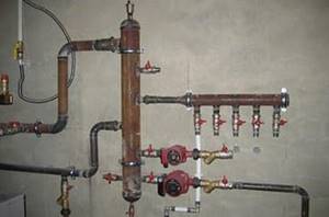
Calculations of the size of a hydraulic arrow for heating begin with the diameter of the pipe, which is suitable for a particular system.
For calculations you will need the following data:
- Boiler power (kW) - W.
- The difference between the flow and return temperatures is ΔT.
By substituting the data, you can use the formula to calculate the minimum internal diameter (D) in mm.
2-3 internal diameters of the device should “fit” between the nozzles.
But not everything is as simple as it seems. To make an arrow yourself, you need welding skills. The services of a hired specialist will cost quite a bit. It is not always easy to find high-quality pipes with straight threads, then you will have to resort to the services of a turner. As a result, the total cost of materials, labor and time may even exceed the cost of purchasing a ready-made factory device.
There is one more point in which homemade products are inferior to factory-made analogues. Since they do not have a thermal protective casing, the separator radiates heat where it is not intended by the owner.
Purpose
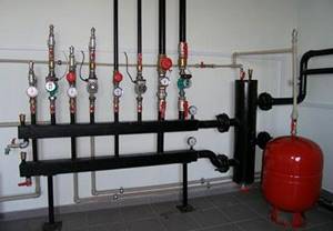
The purpose of installing a hydraulic distributor in a heating system is to separate coolant flows, as well as to protect boiler equipment.
Let's consider the main specific situations in which this device can be useful in a heating system:
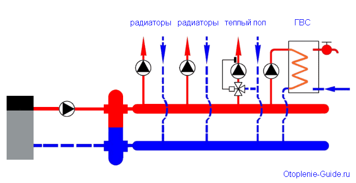
- When it is necessary to create two or more heating circuit circuits with different coolant flow rates. For example, a docked circuit requires more flow than the main one from the boiler. In this case, there are two ways to solve the problem: increase the power and circulation of the main circuit, which will not be economically justified and will lead to a rapid depletion of the equipment’s life. Another way is to install a hydraulic arrow, which will regulate the flow.
- In heating schemes that include boilers, heated floors and several circuits, a hydraulic separator will help to avoid the negative impact of these systems on each other. When turning any of the elements on and off, the overall balance of the system will not be disrupted.
- If there are several circuits (from one boiler), each of which has its own circulation pump. The hydraulic arrow does not allow them to oppose each other. The devices operate smoothly, the coolant is distributed evenly and in sufficient quantities in all circuits.
- There are several boilers that are combined into a single heating circuit. You can’t do this without installing a hydraulic arrow.
- Maintainability is another plus that appears when installing a hydraulic distributor. The device makes it possible to maintain the functionality of all circuits, except for the one that needs to be turned off.
- In some situations, equipment may be subject to temperature changes. A sudden supply of cold liquid to a heated element of the system can lead to cracks and failure. Cast iron heat exchangers, radiators, etc. are especially sensitive to such changes. This happens when heating is started, during repair work, emergency shutdown, etc.
These are the main functions that the hydraulic gun performs. During operation of the device, sediment accumulates in its lower part from impurities contained in the coolant (scale, rust, sand, and other dirt).
A special tap is installed here to remove sediment, and many attribute this to the additional advantages that the hydraulic distributor provides.
After all, cleaning the liquid from impurities has a beneficial effect on each element of the system and extends their service life.
In addition, the device is equipped with the ability to bleed air dissolved in water. If it accumulates in radiators, it leads to a decrease in heating efficiency. So the hydraulic separator is also an air vent.
In the warranty card for some types of equipment you can read that the manufacturer is responsible and is ready to accept faulty equipment only if there is a hydraulic separator in the system.
Separators with magnetic traps
Pneumatex separators with magnetic traps (DN 20 – DN 400 mm) trap insoluble iron impurities in water much more effectively than conventional separators. The rod(s) with a powerful magnet are inserted from below from the outside into the separator sleeve and removed before the operation of washing out the sludge without violating the tightness of the system. The magnetic rod is separated from the water by the walls of the sleeve and does not require cleaning or protection from corrosion. The sleeve is made of non-magnetic material, so the magnetic particles quickly settle down and then the sludge is washed away through the valve. For effective flushing, the valve is offset from the center (creating a vortex effect). Separators with magnetic traps also contain conventional separating elements and have all the degassing and non-magnetic particle removal properties of conventional separator models.
The principle of operation of the hydraulic arrow
Let's look at the operating principle of the hydraulic separator. Since there is nothing inside the pipe of the device, it is clear that the regulation of the coolant is carried out due to physical laws. How it works:
When the equipment is just starting up, the temperature of the coolant is not yet sufficient to somehow heat the room, and the circulation pumps are already dispersing it through the radiators. The water, reaching the hydraulic arrow, is directed downwards and rotates in a small circle and the boiler works for itself, quickly increasing the temperature of the coolant.
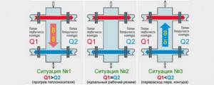
Hydraulic processes occurring in a hydraulic arrow
After the balance in the supply and return temperatures is restored, the flows practically do not mix, and the hydraulic arrow only performs the functions of collecting impurities and air from the liquid. But in practice, such an equilibrium is practically unattainable and short-lived, so the presence of a hydraulic arrow will always be justified.
If for some reason the system flow increases, and the ducts in the boiler are smaller in diameter and simply cannot provide a higher flow. Then the water in the hydraulic arrow is mixed (the required volume of liquid is added from the return to the supply) and each element of the system receives as much as it requires - the boiler is smaller, the pipeline branches are larger.
Long-burning heating boilers especially urgently need to install a hydraulic arrow, since they have several combustion modes (from ignition to extinction) and at each stage of operation it is necessary to create stable conditions of pressure and temperature.
Design, purpose and principle of operation of the hydraulic arrow
The hydraulic arrow for heating consists of a bronze or steel body with two pipes for connecting to the boiler circuit (supply pipe + return pipe), as well as several pipes (usually 2) for connecting the heat consumer circuits. An automatic air vent is mounted in the upper part of the hydraulic separator through a ball valve or shut-off valve. at the bottom there is a drainage tap. A special mesh is often installed inside the housing of factory hydraulic arrows, which allows small air bubbles to be directed into the air vent.
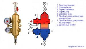
Design of the Valtec VT model. VAR 00.
The hydraulic arrow for heating performs the following functions:
- Maintaining the hydraulic balance of the system. Turning on/off one of the circuits does not affect the hydraulic characteristics of the remaining circuits;
- Ensuring the safety of cast iron boiler heat exchangers. The use of a hydraulic arrow allows you to protect cast iron heat exchangers from sudden temperature changes (for example, during repair work, when the circulation pump is turned off, or when the boiler is turned on for the first time). As is known, a sharp change in coolant temperature negatively affects cast iron heat exchangers;
- Air vent. The hydraulic arrow for heating performs the functions of removing air from the heating system. To do this, in the upper part of the device there is a pipe for installing an automatic air vent;
- Filling or draining coolant. Most of both factory-made and self-made hydraulic switches are equipped with drain valves, through which it is possible to fill or drain coolant from the system;
- Cleaning the system from mechanical contaminants. The low flow rate of the coolant in the hydraulic separator makes it an ideal device for collecting various mechanical contaminants (scale, scale, rust, sand and other sludge). Solid particles circulating through the heating system gradually accumulate in the lower part of the device, after which they can be removed through the drain valve. Some models of hydraulic arrows can be additionally equipped with magnetic catchers that attract metal particles.
What is sludge?
This is mechanical dirt that is carried throughout the heating system by the coolant and clogs the openings of valves, pumps and other mechanical moving parts. These deposits, such as sand, sediment, rust, and magnetite, accumulate. They destroy the surface first, and then the internal parts. Especially often, dirt settles in the boiler firebox, which increases its overheating. Sludge is also formed during friction of mechanical elements. Particles peel off from them and enter the coolant. And just in order to remove all this garbage, we need a sludge separator.
Installation recommendations
Requirements for installing a separator in a heating system.
An air and sludge separator is installed in the supply immediately after the boiler. As noted above, the largest number of bubbles are released from water when it is heated in a boiler. If they are not removed immediately, they will dissolve in the cooling water.
The device is installed in front of the circulation pump. This prevents air bubbles from entering the pump housing, which in turn reduces wear on pump parts.
Separator device for waste water from continuous blowdown
The separator has a simple device; its body is made in the form of a vertical cylindrical container operating under pressure. Based on the permissible pressure, the bottoms of the housing are made flat or elliptical. The supply of purge water to the tank can have a flattened shape or a round cross-section.
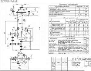
Source of the diagram: cotlomash.ru
The flow of incoming hot water is swirled by supplying it to the wall of the separator tank, thanks to the placement of special guide devices inside. As a rule, the blowing flow rate to the separation device is set to no less than 1% of the steam output of the boiler unit.
At the very bottom there is a drainage fitting for periodically clearing the continuous blowing separator from sludge contaminants. The water level in the tank is maintained automatically by a float-type regulator.
Air separators. Sorting of crushed material
Separation, or sorting, of crushed material according to grain size is carried out either by moving it in an air stream or in a moving stream of water.
The most common is air classification, which is carried out in air separator devices operating on the principle of using centrifugal forces, as well as gravity forces.
There are three types of air separators:
- Centrifugal-air, or mechanical, in which the air flow is closed inside the separator itself.
- Air-through, or pneumatic, with a through-flow air flow.
- Rotating, with air flow through.
The centrifugal air separator (Fig. 1) consists of two cones, concentrically inserted into one another. In the inner cone 1 on the central shaft there is a fan impeller 5, a plate 4 and a centrifugal blade wheel 3.
Rice. 1. Centrifugal air separator: 1-pipe for removing the finished product; 2-outer cone; 3-centrifugal wheel; 4-washing plate; 5-fan impeller; 6-turn doors; 7-inner cone; 8-pipe for removing large particles for re-grinding.
The product is fed from the mill onto a rapidly rotating plate 4 and is thrown by centrifugal force towards the wall of the cone. A fan located above the plate creates an upward air flow. Particles of material are carried away by the air and pass through wheel 3, where small particles are separated; the particles then fall into the annular space between the cones. Larger particles that did not fall out under the influence of gravity are thrown to the walls of the inner cone and removed through pipe 8 into the mill for re-grinding.
Small particles slide down the walls of the outer cone 2 and are removed as a finished product through pipe 7.
The air, freed from material particles, returns through the gaps between the rotary flaps 6 into the internal cone of the separator and thus completes a closed cycle.
Separators with a continuous air flow differ favorably from mechanical separators in the absence of rotating parts. In the separator itself, only larger particles are separated, and the finished product is removed in a separate cyclone, with a fan installed outside the separator.
The simplest and most common separator of this type (Fig. 2) consists of two cones, forming two separation chambers - internal and annular.
Rice. 2. Air-pass separator: 1-pipe for introducing the initial product; 2-inner cone; 3-outer cone; 4-turn sashes; 5-pipe for discharging the finished product; 6-pipe for removal of large particles.
The grinding product enters the air flow through pipe 1 at a significant speed (15-20 m/sec) and enters the annular space between the inner cone 2 and the outer 3. Here the flow speed is reduced to 4-6 m/sec, due to which it is under The largest solid particles fall out due to gravity. Next, the flow goes around the upper edge of the inner cone and passes through the rotary guide blades (flaps) 4, which give it a rotational movement.
The intensity of particle separation depends on the position of the blades. If the blades are placed tangentially, then the precipitation of particles in the inner cone occurs mainly under the influence of centrifugal force, but if they are placed radially, then the precipitation occurs due to inertial forces when the direction of movement changes. Larger particles fall out in the outer cone, which are sent back to the mill through pipe 6. The finely ground product exits along with the air through tube 5 and is sent to the cyclone, where it is separated from the air flow.
Rotating separators with a through-flow air flow are made in the form of a series of plates (flaps) mounted on angles and rotating with the mill, or in the form of several disks with blades rotating in a horizontal plane, which are installed directly above the mill (the so-called turbine separators).
A.G. Kasatkin Basic processes and apparatus of chemical technology (Chapter XVIII. Grinding, screening and dosing of solids / Fine grinding)
The Importance of Pall Rings
If you are thinking about purchasing an air separator, you will probably be curious about how flamcovent separators “fish out” even tiny air bubbles from the flow so quickly and efficiently.
The housing of these devices contains special devices – pall rings. Water comes into contact with the surface of these rings, and they attract small and larger air bubbles located in it. To ensure that the water level in the separator is constant and nothing interferes with the elimination of air, a float air valve is installed in the upper part of the device.
flamcovent air separators are manufactured in two versions:
- Device with brass body and threaded fastening.
- Air separator with steel body coated with enamel. Mounting type: welded or flanged.
Device
So, what is a hydraulic arrow in a heating system? A hydraulic arrow is a hollow pipe (the cross-section can be round or square) from which pipes emerge. Usually they are located in pairs on opposite sides, but there are options (see “Types of hydraulic separators”).
Materials from which the device is made:
- Steel (stainless steel or low carbon).
- Copper.
- Polypropylene.
Plastic models are suitable for systems from 13 to 35 kW. They are not used in combination with heat generators running on solid fuel, and the temperature in the system should not exceed 70 °C.
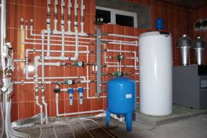
Heating system with hydraulic arrow
An automatic air vent is installed at the top point. A drain valve is usually connected to the downward opening to remove dirt. But it is possible to connect an expansion tank to this pipe.

