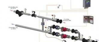
Associated heating circuit - device, use, how to do it
The associated heating pipeline wiring diagram is distinguished by the fact that it is considered self-regulating. If it is assembled correctly, then there is no need to adjust it after installation work. Each radiator in this system should have the same pressure difference between supply and return. Each heating device in a parallel circuit does not stop operating under similar hydraulic conditions.
How does a ride work?
The same pressure difference across the batteries appears due to the fact that the sum of the supply and return lengths is the same for everyone. This can be seen with your own eyes in the diagram. Take any battery from the system, and estimate the total length of the supply and discharge pipelines to the boiler.
Those. all radiators are in similar conditions automatically, and this is actually what other circuits achieve through fine tuning and sometimes cannot achieve. For example, it is not easy to set up a radial circuit, where each battery is connected by a long pair of pipes to one collector. The lengths of such pipelines are varied, the heating devices mutually influence each other, so the system has to be carefully configured.
Pipe diameters
It would be nice if the diameter of the main pipeline (both supply and return) were the same throughout the entire ring, except for connecting the last heating device. Where from the point of branching to the penultimate one, you can use a smaller diameter, because this will no longer be a main line, but a branch to the final heating device in the circuit. Those. the final cut of both feed and return can be with a small diameter.
Maintaining one significant diameter of the lines is necessary to ensure equal conditions for heating devices. Those. so that this “ride” would be a balanced system, where all batteries work stably under the same conditions.
If you start to “play” with savings and reduce the diameter of the line as the liquid moves (after all, less is required with each branch), then it’s very easy to make, so that the group of last heating devices will always be colder, i.e. The system will be difficult to configure.
Similarly, for a small house with 6 - 8 heating appliances, a pipe wire with a diameter of 26 mm is laid from the boiler (external for metal-plastic, for polypropylene and other materials - other values), then to the penultimate appliance - 16 mm. On the contrary, for the return line - from the first battery 16 mm, then from the second - 26 mm ring to the boiler.
However, this is only an example for a small system, and if, for example, the house is large, then the main diameter may need to be much larger so that the pipe wire does not make noise at the end sections, so that the speed in it does not increase by 0.7 m/s. You can determine the required diameter by a simple choice based on the connected power; an example of the calculation can be found on this resource.
Is a ride always necessary?
The associated heating system is more expensive when compared with a dead-end heating system, by 20 percent. The high monetary expense is associated with the use of large-diameter pipes, and namely their connectors - tees on the branches of heating devices and adapters to a smaller diameter to which heating devices are connected.
In a dead-end circuit, the pipe diameters will be smaller, since the entire power is divided into 2 or more arms at the exit from the boiler.
The hitch becomes especially large when it is not possible to run pipes in a ring around the perimeter of the building - from the boiler outlet to its inlet. Then the return line has to be returned in the same way as the supply line.
A complex loop emerges from three pipelines for highways of decent thickness. This must be avoided and the ride changed to the simplest dead-end scheme under certain circumstances.
A simple transition to a dead-end system occurs when the number of heating devices is reduced to 10 or less. Then it becomes possible to balance the heating devices at dead ends and the shoulders themselves without particularly increasing the pump force.
If there are 3, 4 or even 5 heating devices in an arm, there is no problem with balancing all the heating devices and arms in a dead-end heat supply circuit.
And if the same ten heating devices have to be divided along the shoulders as 6 and 4, then it is better to make a self-adjusting ride, just as with 6 heating devices and unequal dead ends, you will have to unnecessarily increase the power of the pump and excessively “squeeze” the batteries located closer to it.
Complications when developing a passing heating system and its configuration
If, as recommended, the diameter of the pipelines is the same, and the heating devices are located on the same multi-story level, and also, if there is no too significant difference in the power of the heating devices, then there cannot be any difficulties with the operation of the system.
More precisely, any problems like “the 3rd heating device does not heat” appear only due to violations of the installation process. For example, polypropylene was soldered with sagging and overlapping diameter inside.
However, if the factors mentioned above that are negative for the operation of the system are present, then differences in the operation of heating devices may appear.
- The one placed higher will take in more heat carrier.
- An overly powerful one will not be able to develop it to its maximum, and when the pump flow increases, very small batteries will begin to make noise due to the high speed.
- Those connected with a reduced pipeline diameter (the final one does not count) most likely will not develop power, since the pressure on them will be less.
In general, the ride is a stable scheme, but “gentle” - you shouldn’t break the rules for its creation, and everything will work as expected.
The only question that remains is the combination of very powerful heating devices with others, because if this is not solved, then the system will be... not applicable at all.
It may be that in the greenhouse we need one heating device of 5 kW, and in the toilet - 0.5 kW. By adjusting the pump and pipe lines for a 5-kilowatt unit, we will apply a pressure that is very high for it to the battery in the toilet and excessively increase the speed through it.
And the solution to the power conflict is the same as in the shoulder circuit - balancing valves. They should, at a minimum, sit on very low-power batteries in a ride, protecting them from high pressure.
However, if heating devices are controlled by local thermal heads, then a situation is possible when some turn off, and some that remain in operation begin to make noise due to the increased flow. Because of this, it is best to install balancing valves on all heating devices at once when developing an associated heating circuit for a home.
One of the main questions remains: is it possible to assemble an associated heating system for a house with your own hands? Of course you can. However, it is necessary to pay great attention to mastering the following issues as well.
Selecting the type of pipes and their diameter, choosing heating devices by power, piping the boiler, piping the heating device, a good selection of connectors, installation options, techniques and problems with the selected pipeline, training in the installation process. As a rule, even beginners in the plumbing business assembled good, efficient heating systems from innovative materials. It is possible that this will continue to happen.
The principle of operation of oncoming and passing CO
So, the associated heating system is a two-pipe heating circuit in which the coolant, both in the “supply” and “return” pipelines, moves in the same direction.
The supply pipe is installed around the perimeter of the heated room (building). All heating devices (batteries) are connected to it in series. The supply pipe ends at the last radiator in the branch in the direction of coolant flow.
The main advantage of this option is the equal length of the supply and return heat supply pipelines to each heating device. This is what makes possible uniform heating of radiators, regardless of their location and distance from the boiler installation (riser). This type of wiring is ideally suited for organizing CO over large areas. Experts note a slight decrease in the temperature of the coolant in the supply pipe, which, as a rule, is not critical.
The disadvantage of this scheme is the complexity of installation and greater consumption of materials (compared to dead-end wiring). The cost of CO increases due to the need to use a main pipeline with a larger cross-section.
In counter, or, as they are also called, dead-end heating systems , the movement of the coolant in the supply line occurs in the opposite direction to the movement of water in the return heating circuit.
A special feature of this CO is the different lengths of the circulation rings. In other words, the further the heating device is located from the boiler installation or riser, the greater the length of the pipeline is involved in this circulation ring. This inequality is the main disadvantage of dead-end SOs.
The advantages of CO with counter-movement of coolant are:
- using fewer pipes, fittings, etc.;
- Possibility of implementation in houses with complex multi-level systems.
This method of laying a pipeline has shown itself to be excellent in systems with a small number of radiators in each branch and with a difference in length of no more than 20 m.
Next, we will consider in more detail all the advantages and disadvantages of these types of wiring.
Characteristics and specifics of the system
The heating system with the parallel movement of the coolant was designed in 1901 by engineer Tichelman. In such a system, the liquid moves in the same direction along two circuits: supply and return. The length of the pipes along the contours is the same, the hydraulic conditions are similar. Thanks to this, the final heating device heats up just as well as the first. This system makes it possible to heat all rooms equally and save fuel. The associated heating system has an alternative name - “Tichelman loop”, in honor of its creator. Installation of such a system is recommended for heating large rooms with 10 or more heating devices. In small houses, the use of such a system is advisable.
To install a passing system, in most cases a circular pump is required. A gravity-flow system is possible with a relatively small number of radiators (no more than 10) and single-story wiring.
Pipe system
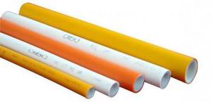
Both the upper and lower wiring of the Tichelman loop are usually performed with PPR pipes. If concealed piping is required, a PEX system with push-on fittings is recommended. If pipes are laid in dense foundations, a thermal insulation shell should be used.
The Tichelman heating system for a one-story house is extremely simple. The coolant supply pipeline runs from the heating unit along the entire radiator network. The nominal diameter of the pipe is maintained until the penultimate radiator in the row, after which a transition is made to the radiator connection diameter, usually 20 mm polypropylene or 16 mm PEX. The return current pipeline is laid in the same order, but towards the supply, that is, the first radiator in the direction of the hot coolant flow is connected with a reduced diameter.
If the Tichelman system is installed on several floors, installation of a vertical riser is required. The main supply pipe follows to the highest point, from where a branch is made to supply the upper floor. After this, the main turns downwards, and in this section the supply is inserted for all lower floors. The common return current pipeline is made by analogy with a two-pipe system with counter-movement of the coolant, that is, it simply acts as a collection line.
The diameter of the pipes for the Tichelman loop is calculated using general methods of thermal engineering calculations, based on the selection of the optimal Kvs value of the main pipes. In this case, it is desirable that as the coolant moves, there is no stepwise reduction in the nominal flow rate, otherwise the natural balancing of the system will not be as good. In systems with a length of distribution pipelines of up to 120 m, the optimal nominal diameter of the main pipes is at least 270 mm2, and for radiator connection pipes - about 130 mm2.

Advantages and disadvantages
The passing system has more advantages than disadvantages.
Advantages of a system with associated water movement:
- The entire heating system heats up equally, from the initial heating element to the last heating element. All rooms will be equally warm.
- There is no need to use expensive equipment and difficult balancing.
- Possibility of installing heat regulators.
- The process of installing a passing heating system is possible with your own hands; no special skills are needed.
- The system has a long service life.
- Greater reliability and fewer malfunctions.
- The system can be installed under the floor.
- The scheme is applicable for two-story houses.
- The system will work independently.
- Very high pipe consumption. Their length is longer than in conventional systems. The pipes require a decent number of shut-off valves.
- The pipes have a larger cross-section when compared to conventional circuits, which means they are more expensive.
- With a complex combination of rooms, the use of the diagram will be impossible due to limitations on the contours (you cannot use right angles, different heights of pipes).
- With a large house area and several floors, such a system will cost a large amount.
What is Tichelman's loop
The Tichelman loop (also called a “passing circuit”) is a heating system pipe routing diagram. This scheme simultaneously combines the advantages of two common schemes: Leningrad and two-pipe, while having additional advantages.
Compared with a two-pipe scheme, when using a Tichelman loop there is no need to install expensive control systems. Heating devices work like one large radiator. The coolant flow is the same throughout the entire heating circuit. There are no narrowing pipes and dead-end radiators, where the flow is worst. The disadvantage compared to a two-pipe heating scheme is that the entire branch must be made with a large-diameter pipe, which can greatly affect the cost of the entire system as a whole.
If we compare it with the Leningrad (single-pipe) scheme, the advantage is that the coolant will not pass through the pipe past the radiator. The Leningrad circuit is very demanding in terms of circuit design and installation. If you are not highly skilled in performing either the first or the second, it will be impossible to force water to pass through the heating device; it will pass through the pipe. The radiator will remain slightly warm. In addition, in the Leningrad scheme, the first radiators in terms of water flow will be hotter than the next ones. Since the water will reach them already cooled. The disadvantage of the Tichelman loop compared to the Leningrad loop is that the pipe flow rate almost doubles.
Of the general advantages, I would like to note that such a scheme is difficult to unbalance. The conditions for coolant movement are almost ideal, which also has a positive effect on the operation of the heat generator (be it a boiler, solar systems or something else).
The main disadvantage of the associated heating scheme is certain requirements for the room. In practice, it is not always possible to organize a circular movement of the coolant. Doorways, architectural features, etc. may interfere. In addition, it can only be used for horizontal wiring; for vertical wiring, the Tichelman loop is not applicable.
Classically used schemes
Classically, one-pipe or two-pipe systems are used for heating houses. The single-pipe scheme involves the installation of one circuit with a coolant.
The key advantage of such a system is the short entire length of the pipeline. Of course, the cost of installing the system is lower, the installation process is faster, and the accident rate is lower. The downside of this scheme is the reduction in water temperature as it passes through the pipes; the final heating device can be very hot.
Applicable schemes for the associated heating system
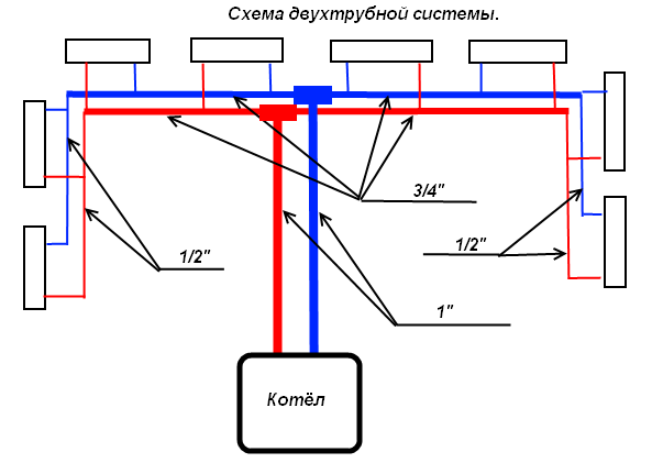
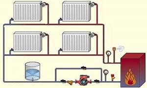
The two-pipe scheme (double-circuit) requires the installation of two circuits to move water along a closed circuit from the boiler to the heating radiators. The first pipe supplies heat from the boiler to the heating devices, the second is considered the return pipe, and the cooled water moves in the opposite direction. The wiring diagrams in both cases are very simple.
With a dual-circuit circuit, the batteries are connected in parallel; they can be selectively closed if necessary.
Two-pipe classic systems are also called dead-end systems. An important difference from the “Tichelman loop” is that the supply of heat carrier to the supply and return lines goes in a wide variety of directions. Hot water goes from the boiler to the battery, returns heat and is discharged into the “return”, moving towards the boiler. The counter movement of water has certain disadvantages: heating devices closest to the boiler heat up faster and the rooms are not heated equally.
Dead-end and parallel movement of the coolant
The associated heating system for a private house has advantages when compared with a dead-end hydraulic system. The coolant moves in one direction, the water travels the same distance, and this ensures that the system is perfectly balanced. Heating devices are used of equal size and power.
Traditionally used heating schemes
- Single-pipe. The coolant circulates through one pipe without the use of pumps. On the main line, radiator batteries are connected in series; from the very last, the cooled medium (“return”) is returned to the boiler through a pipe. The system is simple to implement and economical due to the need for fewer pipes. But the parallel movement of flows leads to a gradual cooling of the water; as a result, the media arrives at the radiators located at the end of the series chain significantly cooled. This effect increases with increasing number of radiator sections. Therefore, in rooms located near the boiler it will be excessively hot, and in remote ones it will be cold. To increase heat transfer, the number of sections in the batteries is increased, different pipe diameters are installed, additional control valves are installed, and each radiator is equipped with bypasses.
- Two-pipe. Each radiator battery is connected in parallel to the direct supply of hot coolant and the “return” pipes. That is, each device is equipped with an individual return outlet. With the simultaneous discharge of cooled water into the common circuit, the coolant is returned to the boiler for heating. But at the same time, the heating of heating devices gradually decreases as they move away from the heat supply sources. The radiator, located first in the network, receives the hottest water and is the first to return the coolant to the “return” circuit, and the radiator located at the end receives the coolant last with a lower heating temperature and is also the last to return water to the return circuit. In practice, in the first device the circulation of hot water is the best, and in the last the worst. It is worth noting the increased price of such systems compared to single-pipe systems.
Both schemes are justified for small areas, but are ineffective for extended networks.
An improved two-pipe heating scheme is the Tichelman heating scheme. When choosing a specific system, the determining factors are the availability of financial capabilities and the ability to provide the heating system with equipment that has the optimal required characteristics.
Installation method
The installation of a two-pipe associated heating system is carried out according to a certain method, where the first stage is the selection of the pipe diameter, and the final stage is the installation of a circulator pump.
Calculation of pipeline diameter
There is a scientifically based method of calculation. The pipe cross-section is selected based on the volume of coolant passing through the pipe per unit time. The calculation starts from the distant heating device using the formula:
where: G ? water consumption for heating the house (kg/h);
Q? heat output required for heating (kW);
c ? heat capacity of water (4.187 kJ/kg? °C);
?t ? the temperature difference between hot and cold coolant is assumed to be 20 °C.
Next, calculate the cross-section of the pipes using the formula:
where: S ? cross-sectional area of the pipe (m2);
GV? volumetric water flow (m3/h);
v? the speed of water movement is in the range of 0.3–0.7 m/s.
The resulting figure is the cross-section; based on it, the diameter inside the pipeline is selected.
A similar calculation is carried out for all heating devices up to the boiler.
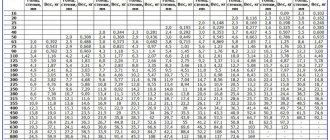
When calculating, you can also look at the table of the dependence of the internal pipe diameter on the thermal load.
Table of dependence of internal pipe diameter on thermal load
The following guidelines can be provided:
- For heat losses of up to 15 kW (150 sq. m.) of area, pipes with a diameter of 20 mm are suitable.
- For losses from 15 to 27 kW (up to 250 square meters), pipes with a diameter of at least 25 mm will be needed.
Making calculations using the given formulas or hydraulic tables is considered a difficult task for the home owner, so you can base it on the recommended pipe diameters.
The following conditions must be met:
- Lay the pipes under the floor covering to avoid high-rise contours. If this is unrealistic, then it is necessary to take into account the configuration of the house and strive as much as possible for the same height of pipe laying.
- The pipe material is metal-plastic or polypropylene reinforced with aluminum foil. Such pipes are stronger and will last a long time.
- Heating devices are installed bimetallic or steel with a bottom connection system. Such batteries have higher hydraulic resistance, which balances the system. The power of heating devices should be the same throughout the entire house.
- Each battery is equipped with a balancing valve on the return line. It is advisable to install thermostats.
Boiler installation
The room where the boiler is installed must have a height of at least 2.5 m. The volume of the room is recommended from 8 cubic meters. The heat generator must be selected depending on the area of the heated house. Boiler heating capacity 10 kW. m is equal to 1 kW. Based on this, the power for the entire system is selected.
The boiler piping consists of a set of shut-off valves; it is installed in some places:
- On the make-up pipe.
- On both sides of the pump.
- At the expansion tank.
- On the pipes coming from the boiler.
Mainline pulling
When installing the associated heating system distribution line, the following should be provided:
- The outlet branch of the main line must be located below the supply branch.
- The lines from the heat supply and heat removal pipes must be parallel to each other.
- The expansion tank must be placed above the heating boiler.
- It is necessary to install valves for flushing water on the closing batteries. It is recommended to install a thermostatic head on any battery to ensure a comfortable temperature.
- When laying the pipeline, right angles are excluded so that there are no air pockets in the system.
- The expansion tank must be placed in a heated room.
- All pipe diameters, connectors and taps must match each other. Pipes of different diameters cannot be installed in an attempt to save money. The water pressure in the system will be disrupted.
Installation of a circulation pump
It is unreasonable to rely on gravitational circulation, since there are 10 or more batteries in the associated heating system. Gravity will not be able to work without forced pressure. The circular pump is placed on the return branch near the boiler. The pump is driven by a circular pump and three valves. It is recommended to install a filter.
A circulation pump is installed on each floor
The associated heating system is installed in one-story and two-story buildings. In buildings of two floors, certain points must be taken into account during installation:
- A circulation pump is installed on each floor. If a problem occurs within the boundaries of one floor, the heating supply will be fully operational on the other.
- An individual installation process is recommended for any floor.
Variants of the Tichelman scheme
With the correct construction of the Tichelman scheme, the heating system assumes the creation of identical conditions for the operation of the radiator. This applies to pressure drops, despite the fact that radiators have equal surface areas, and, consequently, an equal level of heat transfer. To draw diagrams correctly, you need to practice for some time.
The door can be bypassed in several ways: the pipe can be laid on top. When choosing this option, please note that the area above the door must be equipped with an automatic air vent: this will not allow air to accumulate. The appearance of the room suffers. Also, the air vent may leak from time to time, which is quite impractical.
Variants of the Tichelman scheme:
- Option in a one-story house. The pipe can be laid below the floor level. But this can be inconvenient if the flooring has already been done.
- Scheme for two floors. According to the scheme, the entire system is tied together, not individual floors. The supply and return of main pipes having a diameter of 20 mm are carried out. And radiators are already connected to them using a 16 mm tube.
- Trim for three floors. One piping is performed for all floors. The risers have a diameter of 25 mm, supply and return are 20 mm, the pipe for the outlet to the radiators is 16 mm.
If possible, it is better to connect each floor separately, while connecting an individual pump for each. It should be taken into account that the use of one pump if it breaks down can lead to the entire heating system failing at once. The Tichelman scheme can be used for heating installations in all types of premises. It involves uniform heating of the radiators, and it is quite easy to install if the circuit is drawn up correctly.
Acceptable complications during installation
If the heating pipes have the same diameter and the heating devices are placed at the same height, in most cases there will be no problems during or after installation.
Problems may arise if the order of the installation process is not followed:
- Low-quality soldering of polypropylene pipes leads to a narrowing of the pipe diameter.
- Installation of radiators made of various materials and different capacities will upset the balance of the system.
- Lack of balancing valves to equalize hydraulic pressure.
- Placement of a highway branch with a height difference.
- Incorrect pump selection. The pressure must be at least 0.2 kgf/cm2.
- The use of pipes of different diameters can lead to imbalance of the system and difficulty in passing the coolant.
A dual-circuit heating system is recommended for heating single-story houses. It does not require complicated calculations, balancing or special installation methods. The cost of such a system is more expensive than the classic one, but this is offset by durability and ease of operation. Moreover, the owner of the house can install this type of system on his own, without using complicated engineering solutions, materials and tools.
Applications of the Tichelman loop
Increased consumption of materials is not always better, so the Tichelman system is rarely used in a two-story house. The exception is a highway with radiators placed around the perimeter of the building. The ring system will require significant costs for materials, but the arrangement of a closed ring is carried out only if there are no obstacles in the form of doorways or floor-to-ceiling windows. We will have to lay another line to return the coolant to the heating device.
If the loop is lengthened, moved away from the heater, the cross-section of the pipes is increased, or a powerful circulation pump is selected, otherwise the system will not be able to operate at full capacity.
To reduce coolant costs in the area where the first batteries are connected, the diameter of the pipeline should be reduced, this will help maintain water pressure in subsequent sections. The diameter is reduced only according to preliminary calculations, otherwise radiators located at a considerable distance from the heating device will not receive a sufficient amount of coolant.
It turns out that using two-pipe wiring with a passing water flow is only possible if the total length of the main line is 70 meters or more, on which 10 radiators are installed. Otherwise, the associated wiring will not justify the investment.
Associated and dead-end movement of the coolant. — Notes from a young engineer
In heating systems with two pipes, a parallel movement of the coolant is often used. Why? What are its advantages? Why is a dead-end scheme worse? First, let’s try to figure out “who is who,” so to speak. So, the parallel movement of the coolant is a similar movement of the coolant in which water in the supply and return pipelines flows in the same direction (Fig. 1). In the case of an oncoming (dead end) situation, everything is exactly the opposite (Fig. 2)
Fig. 1 Diagram of a heating system with two pipes with a parallel movement of the coolant. Fig. 2 Diagram of a heating system with two pipes with dead-end movement of the coolant.
Let's consider both schemes from the point of view of hydraulics and balancing, the length of pipelines and the installation process. I. Hydraulics and balancing. By hydraulics I mean a clear calculation of pressure losses in branches/rings. Balancing is the connection of branches with each other, and specifically we strive to ensure that all rings/branches have equal pressure losses.
We all know that when calculating the pressure losses of the network, we need to calculate the pressure losses in most of the circulation ring (the most loaded and extended) and in other rings in order to link them with the key circulation ring.
It’s simple: if in some ring the pressure loss is less than in others, then the water will tend to flow directly into this circuit, therefore, in other rings there will be little of it. This means that we do not receive the required coolant flow in each branch and therefore the required heat transfer from the radiators; in this case, the system is considered unbalanced. The hydraulics for the parallel movement of the coolant are surprisingly simple. If you have a branch of heating devices of similar power and size (Fig. 3), then it is enough to calculate the pressure loss in the circuit through any heating device; in other circuits the pressure loss value is the same. The system, by default, is considered hydraulically linked, i.e. balanced and does not require any pre-tuning radiator valves.
Fig. 3 Scheme with parallel movement of the coolant at the same power of the devices. But, if the power of the radiators is different or they have different sizes (which affects the value of the local resistance of the device), then it will be necessary to count the losses through each circuit and link the devices to each other using thermostats (Fig. 4).
Fig. 4 Scheme with parallel movement of the coolant at different power devices. When operating a counter flow circuit for the coolant, in any case, the pressure losses through each circuit are calculated and an automatic radiator valve is installed on each device. But, it must be stated that if thermostats are installed on devices with a parallel flow pattern of the coolant, it is most likely that the valve settings will be enough for balancing. If we have a dead-end circuit, then on the first device on the branch (Fig. 5) we must set the highest setting, i.e. tighten the cross-section as much as possible, and for example, if the system is very long, the valve setting may not be enough, or if we set the largest setting, the cross-section will be reduced so much that water will not flow into the heating device.
Fig.5 Valve setting - diagram with dead-end movement of the coolant.
According to the “Hydraulics and balancing” condition, a scheme with a parallel movement of the coolant is more preferable. But there is one “water stone” in such a scheme. In this scheme there are, in other words, “points of equal pressure.” If the connections to the room heating device are connected to the main line in this place, then water will not flow into the device. What are these dots? I suggest you get acquainted with Figure 6.
Fig. 6 Points of “equal pressure” - a diagram with a parallel movement of the coolant.
It can be seen from the figure that these points are located in the middle of the contour, however, in the case of a much more complex layout, it is more difficult to predict where these points are. And the physics here is simple: At point 1, located on the supply pipeline, and point 2, on the return pipeline, the pressure is the same and, due to the fact that there is no pressure difference between these points, water does not flow through the device.
Advice: try to beware of such points and connect the device further from them. ??
II. Length of pipelines and installation process.
Very often, a passing scheme requires longer highways, but this is not always the case. Everything may depend on the room and placement of devices. As for the installation process, it is easier to install a dead-end circuit, if only due to the fact that the diameters of parallel sections and standard sizes of fittings are not distinguished. According to the condition “Length of pipelines and installation process,” a dead-end scheme is more acceptable.
For simplicity and ease of comparison, the given facts about the patterns of movement of the coolant are shown in summary table 1.
Table 1. Comparison of flow and dead-end heat carrier movement patterns
How does a dead-end heating system work?
A dead-end circuit is a two-pipe space heating device in which, as can be seen from the figure above, the hot coolant is supplied to each radiator through one pipe (supply), and leaves the radiators and goes to the boiler through another pipe (return). Moreover, in this scheme, the movement of the coolant through the supply and return pipes occurs in the opposite direction, while in other (not single-pipe) schemes the liquid moves in one direction. This is a very common option for connecting heating devices, and not only radiators - these can be cast iron or bimetallic batteries, or homemade registers.
Although single-pipe heating can be implemented using a dead-end scheme, this solution is unpopular due to its low heat transfer efficiency and complexity of implementation. The implementation of a dead-end single-pipe scheme is shown below - if the house is designed for 2 or three floors, then, in addition to the standard safety group, you will have to install risers and install an air vent or Mayevsky valve on each radiator. This is an expensive scheme, so it is not often accepted for execution.
An indirect advantage of the dead-end circuit is that it can be used both for heating with forced circulation of coolant, and for solutions with gravitational movement of liquid in pipes. For energy-independent heating of a private house, a system with natural circulation is becoming increasingly popular, so do not forget about the dead-end scheme with top pipe routing in this case.
In any case, with a single-circuit or double-circuit scheme, the following is obvious for the dead-end option: the more radiators connected to the pipe, the slower all subsequent heating devices will warm up. Therefore, it is advisable to divide the entire system into several branches so that each branch has no more than 5-6 radiators. This solution is relevant for both natural and forced coolant movement schemes.
In practice, the advantage of a dead-end scheme is obvious: simple calculations, a simple level of installation, a minimum number of shut-off valves and fittings, and the low cost of the entire project. If we compare with such popular solutions as a two-pipe system with a parallel movement of liquid and with a beam circuit (with a collector), then in terms of compliance with the laws of hydraulics, they are clearly better than a dead-end system - the coolant moves faster, there is no oncoming movement, the radiators warm up evenly and at the same speed. But often it is the efficiency of the dead-end option that wins, especially for heating a house with a small total heated area.
The horizontal scheme with dead-end wiring has a variation where a central highway is used. This scheme can be implemented as a pipeline hidden in the floor or wall, which appeals to all homeowners without exception, since a hidden pipeline does not require redesign, remodeling or changing the interior of the premises.
When installing a hidden pipeline, for example, when embedding pipes in a concrete floor screed or in grooves in walls, pipes should not be steel, but metal-plastic without joints or polymer with a connection using a fixed sleeve or welding to prevent the possibility of leakage. The only problem when laying a hidden pipeline is its correct and beautiful exit from the wall or from under the floor. You should also avoid any intersections of pipes in a hidden installation option. To avoid intersections, use a cross. When connecting a pipe to a radiator using a crosspiece, you can bend the pipes of the central line without protruding beyond the installation plane.
Also, the implementation of a dead-end system with a central mainline opens up the possibility of connecting other schemes to heating: a “warm floor” system or heated towel rails. Such units are connected using a special mixing module, which includes a circulation pump, mixing taps and temperature sensors. The mixing module makes the operation of the connected modules independent of the main heating circuit, and any number of new connected circuits will not affect the operation of the main circuit.
How much water should there be in the “loop”?
It is quite obvious that in order to properly organize heating in a house, it is necessary to know the specific amount of coolant that will fill and operate the entire system. Before proceeding directly to calculating the amount of water required, you need to determine what the heat loss of the entire house is. To do this you need to know such parameters as:
- temperature difference between the environment and indoors;
- the value of the reduction factor;
- .
Then all that remains is to use the following type of formula: G = S * 1 / Po * (Tv - Tn)k. Having received the heat loss value, you can begin to determine the amount of water. To do this, we use the following formula – Q = G/(c*(T1-T2)). To use it, you need to know the specific heat capacity of water, as well as its temperature both in the return pipe and in the supply pipe.
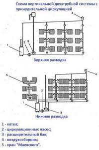
Diagram of a vertical two-pipe system
System calculation: pipe diameter
Of course, drawing up a detailed project is what the Tichelmann loop heating installation first requires. In this case, the system is calculated in the usual manner. In order to determine the required pipe diameter, you must first calculate the required thermal power of the system. This can be done using the formula Q = (V * Δt * K), where V is the volume of the house, Δt is the difference in temperature indoors and outdoors, K is the heat loss coefficient. The last parameter depends on the degree of insulation of the task.
No thermal insulation (or minimal)
Average level of thermal insulation
High-quality insulation, use of plastic windows and modern entrance doors
Next, you need to determine the speed of movement of the coolant in the lines. The range of values for the optimal indicator in this case is between 0.36 and 0.7 m/s. All data obtained should ultimately be inserted into a special table of pipe sizes. Most often, metal-plastic with a diameter of 26 mm is purchased for the return and supply lines in such systems. Radiators are connected with 16 mm sections.
Hydraulics data
The operation of the system, based on the Tichelman loop principle, is highly stable. This fact is clearly demonstrated by hydraulic calculation data, however, this requires compliance with a number of installation rules.
The main functional element of such a system remains the hydraulic pump. It creates pressure at the outlet, that is, at the supply, and a vacuum at the inlet, the return. Numerically, the magnitude of both values decreases with distance from the pump, and the pressure drop does not occur linearly, it is described by the quadratic value of the dynamic pressure. This pattern can be traced for both the supply branch and the return branch; the fall can be conventionally described using the example of a 100 m long pipeline:
| Distance from the pump in the direction of coolant movement (m) | Supply pressure (% of nominal) | Return vacuum (% of nominal) | Radiator pressure drop |
| 10 | 90 % | 5 % | 95 % |
| 20 | 75 % | 20 % | 95 % |
| 30 | 55 % | 35 % | 90 % |
| 50 | 45 % | 40 % | 85% |
| 60 | 40 % | 45 % | 85 % |
| 70 | 35 % | 55 % | 90 % |
| 80 | 20 % | 75 % | 95 % |
| 90 | 5 % | 90 % | 95 % |
These are averaged data, but even from them it is clear that, despite the apparent uniformity, the pressure loss in the middle of the radiator network is slightly higher than at the edges. Indeed, due to the proportional change in pressure and vacuum in each radiator, an almost identical pressure drop is maintained in each heating device, however, for the correct and stable operation of the Tichelman loop, a number of rules must be followed, which will be discussed further.
Installation stages
The heating system is assembled according to this scheme in the usual manner. That is:
The boiler is being installed. The height of the room where it will be installed should not be less than 2.5 m. In this case, the minimum allowable volume of the room is considered to be 8 m 3. The boiler is usually selected based on the fact that it requires 1 kW of power per 10 m2 of room.
Radiators are being hung. The most popular type of this equipment is bimetallic batteries. Before hanging radiators, markings should be made. This heating equipment is usually mounted on special brackets.
The highways themselves are stretched. Most often, metal-plastic pipes are used to assemble heating systems, including associated heating systems. Their advantages include ease of installation, ability to withstand even very high temperatures and durability.
A circulation pump is installed. This device is usually mounted in close proximity to the boiler, on the return pipe. It needs to be inserted through a bypass with three taps. A filter must be installed in front of the circulation pump. This addition will significantly extend its service life.
An expansion tank and a safety group are installed. The first one is connected to the return line through one pipe. Of course, for the Tichelman system you need to choose a membrane expansion tank. The safety group usually comes with the boiler.

Nuances of a three-pipe heating system
It is very important to design the correct heating system, since it determines the warmth and comfort in the house during the entire cold period, which in our country is characterized by severity. A heating system with a coolant in the form of water can be one-pipe, two-pipe, three-pipe or even four-pipe
The Tichelman system is often called a three-pipe system.
A three-pipe system is qualitatively different from a two-pipe system, but does not reach the level of a four-pipe system. Such a system can be called a compromise: its distinguishing feature is flexibility and affordable cost when compared with the costs of installing a four-pipe system. Installing a three-pipe system is the most optimal and economical option.
- Easy to use. The system works very simply if you first understand the principle of its operation.
- The automatic control process ensures that the coolant and its flow rate remain constant for each consumer.
- The system can be used to equip buildings of any type.
- To operate, the system does not require the installation and use of check valves: it works thanks to a circulating pump.
Three-pipe heating systems can be open or closed. Closed systems require continuous operation and circulation of the coolant to the heat source and to the heating source. Open systems are characterized by inequality. After the network water is poured out, the water comes into contact with the atmosphere. The open system can be replenished anywhere.