Organization of basic access
All boiler inspection and repair operations require lowering the lower control panel. It is also necessary to remove the outer casing.
Removing the front panel
- Loosen the front panel mounting screws “A” located at the bottom of the front panel. (Fig. 1.1);
- The control panel slides down and extends forward, pivoting on two side hinges; the panel remains in a horizontal position on the floor, which allows access to the internal components of the device (Fig. 1.2);
- to increase the service space, you can lift and rotate the panel to a completely horizontal position (Fig. 1.3);
- Unscrew the screws “B” from the bottom of the front panel (Fig. 1.4);
- Lift the front panel up and forward, after unscrewing the screws on top. (Fig. 1.5)
Removing the front combustion chamber cover
- Unscrew the screws “C” (Fig. 1.6);
- Remove the front cover from the guide pins
(Fig. 1.7).
Removing the side panels
- Unscrew the 4 screws “D” for each of the side panels (Fig.1.8);
- Pull the bottom of the panel away from the chassis, then lift it slightly and disconnect it from the boiler (Fig. 1.9).
Primary heat exchanger repair
The exchanger deteriorates due to poor quality coolant or the materials from which it is made, as well as other factors. Pressure, high temperatures and their differences lead to cracks, which is why the element begins to work less powerfully and breaks down over time. The life of the heat exchanger can be extended if purified water is supplied and the boiler is not overloaded.
We recommend: Do-it-yourself heating (heating) of a greenhouse: 8 best projects
It will be more difficult to eliminate cracks than clogs. The heat exchanger is soldered for this purpose. Select solder from the same material as the unit itself. Boiler heat exchangers are usually made of copper, less often cast iron or steel. Aluminum, silicon, manganese, nickel and zinc are added to the composition.
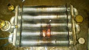
Leaks on the primary heat exchanger can occur due to exposure to flames, water hammer, and in some cases they are caused by corrosion
Additional solder requirements:
- melting point not lower than 700 °C;
- sufficient viscosity;
- fluidity is the same as that of a heat exchanger.
Copper-zinc solders are considered one of the best. They are used for soldering most non-ferrous metals with a higher melting point than the support material itself. Solders with inclusions of silicon or tin - up to half a percent - are safer for the human body.
It is better to avoid copper-phosphorus materials, and if exchangers are soldered with them, do so without any load such as shock or vibration. Well-chosen solder is half the battle.
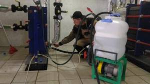
Heat exchangers are soldered with gas burners and blowtorches. Before soldering, the desired area is cleaned with fine-grained sandpaper and wiped with a rag with a solvent, and then heated. The area is heated with a hairdryer or a weak burner/soldering iron. At this moment, the main thing is to get into the temperature corridor and take into account subsequent cooling. Barely noticeable damage is found by small greenish spots.
Before heating, the water is drained, and its remains are removed with a compressor or blown out through a flexible hose. The hose is fixed by thread if it has a union nut and the design features allow this. If you leave water, it will take away part of the thermal energy.
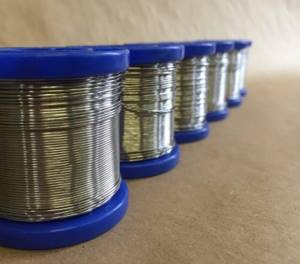
Solder spools: At high temperatures, the material wets the base and spreads across it, gets into the smallest gaps and stretches, resulting in an intermediate layer of base and solder combination
Solder is preferred in the form of a wire or rod: when soldering, the molten end will be well immersed in the flux, which will stick to it. If the wire lays on the exchanger itself too intermittently or loosely, the preheating was weak. After work, the soldering area is sometimes coated with heat-resistant paint for better insulation.
Over the next two weeks, the soldered area is checked daily for integrity. At the first detected leak, you should contact a specialist. If it appears in the first fortnight, it means the soldering was of poor quality.
The flux is suitable for universal use, as well as gel soldering flux. Avoid rosin, unusual options like aspirin and others.
Access to the combustion chamber
Removing the combustion chamber front panel
- Unscrew the screws “E” (Fig. 1.10);
- Remove the combustion acme front panel.
Removing the burner and nozzles
| 1.3.3 Dismantling the electrodes Before carrying out this operation, unscrew and slide the burner forward (see previous section).
|
- Unscrew the screws “F” from the burner (Fig. 1.11);
- Disconnect the burner (Fig. 1.12);
- Disconnect the electrodes (see section 1.3.3
); - Unscrew the injectors using a socket wrench
7 mm;
- Reassemble in reverse order
Dismantling the heat exchanger
- Drain the water from the boiler;
- Remove the overheating thermostat, DHW flow sensor and heating temperature sensor “I” (Fig. 1.17);
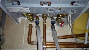
- Loosen the 4 nuts “J”, which are attached to the heat exchanger of the coolant supply and return tube (Fig. 1.18);
- Remove the heat exchanger from the boiler (Fig. 1.19).
Reassemble in reverse order, paying attention to the following points:
a
—
Insert the electrode into the landing socket carefully, otherwise it may burst;
b –
Make sure that the left and right electrodes are installed correctly: they must face each other in order to ensure the required spark gap;
- –
Check that the wires are connected correctly; - –
Check that the rubber bushing completely covers the junction of the wire and the electrode. (Fig. 1.19)
Removing the differential pressure switch
- Disconnect the electrical connectors “N” and the silicone tube “O”
- Disconnect the connectors “K” of the silicone tubes
“L” (Fig. 1.20);
- Unscrew the screws “M” from the top of the combustion chamber
(Fig. 1.21);
- Disconnect the pressure switch (Fig. 1.22);
- Disconnect the relay from the mounting bracket.
Fan removal
- Disconnect the electrical connectors “N” and the silicone tube “O”
- Unscrew the screws “P” and remove the fan locking clamp “Q” (Fig.1.24);
- Unscrew the screws “R” (Fig.1.25);
- Remove the fan together with the mounting bracket from the boiler (Fig. 1.26).
Material of manufacture
The heat exchanger for the boiler is made from durable materials that conduct heat well, are not prone to corrosion and are sufficiently resistant to pressure. Since the cost of the material also has to be taken into account, the choice is limited.
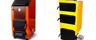
Steel
A steel heat exchanger is cheaper in price, but less durable.
This is the most affordable material. Steel is very strong, but can be processed well. The price is low. The advantage of this option is resistance to high temperatures. Steel is plastic and does not crack when heated, and does not deform even in areas in contact with the burner.
A steel heat exchanger for a solid fuel or gas boiler is prone to corrosion. Water inside the tubes and combustion products in the boiler chamber have a destructive effect on the material. This affects durability. The steel model weighs a lot, which leads to additional fuel consumption for heating the element itself.
The stainless steel heat exchanger is resistant to corrosion and lasts for at least 50 years.
Cast iron
The material is much more resistant to corrosion than steel, and is not afraid of rust and the action of acid anhydrides. The service life reaches 50 years. However, cast iron is a brittle alloy and can crack under the influence of temperature. To avoid damage, the cast iron tubular heat exchanger must be washed: if ordinary water is used, then once a year; if antifreeze - then once every 2 years; if distilled liquid - once every 4 years.
The weight of a cast iron element is even greater, so more fuel and time have to be spent on heating.
Copper
Copper is a noble metal that is not susceptible to any type of corrosion. It is chemically inert and tolerates pressure well. Copper conducts heat better, so less fuel is required to heat the element itself and the flowing liquid. The weight of the copper model is small, the dimensions are compact with a very developed working surface.
The disadvantage is the high price. Also, the copper heat exchanger is too sensitive to heating to high temperatures. More often found in boilers from foreign manufacturers.
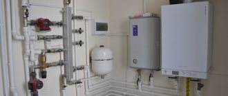
Organizing access to the hydraulic unit
Attention!
Before carrying out the operation, drain the water from the boiler.
Removing the pump pressure sensor
- Disconnect wires “W” from the sensor (Fig. 1.33);
- Unscrew the sensor using a wrench;
- Remove the sensor from the system.
Removing the safety valve
- Disconnect the unloading tube from below;
- Unscrew and remove valve “X” (Fig. 1.34).
Removing the air vent
- Unscrew the valve “Y” from the top (Fig. 1.35);
- Disconnect the valve assembly with the float (Fig. 1.36).
Dismantling the pump
- Disconnect the “Z” clamp (Fig. 1.37);
- Disconnect the clamps “A1” (Fig. 1.38);
- Loosen the nut “C1” (Fig. 1.39);
- Disconnect tube “D1” (Fig. 1.40);
- Unscrew the screws “E1” (Fig. 1.41);
- Remove the pump from the boiler.
Removing the pressure gauge
- Disconnect the clamp “F1” (Fig. 1.42)
- Disconnect the pressure gauge tube (Fig. 1.42);
- Push the pressure gauge out of the socket in the control panel by pressing it from the inside (Fig. 1.43).
Removing the expansion tank
- Loosen the nuts “G1” and disconnect the gas pipes (Fig. 1.44);
- Loosen the nut “H1” (Fig. 1.45);
- Unscrew the nut “I1” (Fig. 1.46);
- Remove the expansion tank from the boiler (Fig. 1.47).
Removing the overheating thermostat
- Disconnect the overheating thermostat wire “J1” (Fig. 1.48);
- Disconnect the thermostat from its mounting location by removing the clamp (Fig. 1.49 /1.50).
1.5.9 Removing the heating circuit temperature sensor
- Disconnect the connector and unscrew the sensor using a suitable wrench (Fig. 1.52).
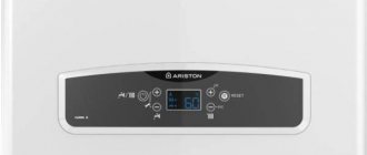
You may be interested in >> Operating manual for gas boiler Ariston Egis plus 24
1.5.8 Removing the DHW temperature sensor
- Disconnect the electrical connector and unscrew the sensor using a suitable wrench (Fig. 1.51).
1.5.10 Removing the DHW temperature sensor
- Disconnect the electrical connector “M1” (Fig. 1.59);
- Disconnect the clamp “N1” and remove the DHW temperature sensor.
When and how often do you need to clean the gas boiler heat exchanger?
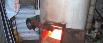
Manufacturers of gas boilers recommend cleaning the heat exchanger annually, or at least once every 3-4 years if a relatively clean coolant of low hardness is used, which does not change with each heating season, and a mechanical cleaning filter is installed in the system. It is recommended to carry it out before the start of the heating season.
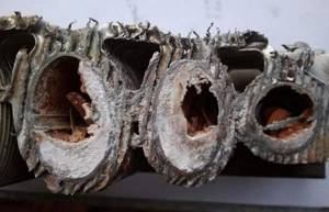
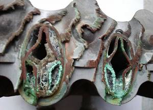
Heat exchanger of a gas boiler in section. The use of contaminated coolant and lack of regular cleaning led to serious consequences: serious overheating and almost complete clogging.
In the absence of regular maintenance, there are signs of a clogged heat exchanger:
- reduction in heating performance - is expressed in a lower (10-20%) temperature of the heating radiators than before and, accordingly, in the room temperature when the boiler is operating at the same constant power;
- increased gas consumption - noticeable if you analyze the meter readings and the operating mode of the boiler for the last month and a month earlier that was similar in temperature (preferably the same month in the previous heating season);
- increased noise or the appearance of new sounds when water moves through the heat exchanger;
- increased operation of the circulation pump.
If internal cleaning has not been carried out for more than a year, one of the above symptoms is observed - it is recommended to rinse the heat exchanger with special chemical solutions over the next few months, which we will discuss later, and then perform mechanical cleaning. Otherwise, contamination and scale not only cause increased consumption and lower heating output, but can also lead to overheating, burnout of the heat exchanger, and failure due to increased load of the circulation pump.
If the boiler is installed in a system with natural circulation, due to a serious reduction in the cross-section (throughput) of the heat exchanger, there may be difficulties with the movement of coolant through the system.
Organization of access to the control system
Attention!
Switch off the power supply to the boiler at the external switch before performing the following operations.
Checking the status of fuses
- Remove the back cover on the control panel
(Fig. 1.54);
- Remove the fuses (Fig. 1.55).
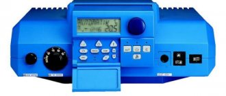
Removing the timer
- Disconnect the electrical connector “P1” from the timer (Fig. 1.56);
- Unscrew the screws “Q1” (Fig. 1.57);
- Remove the timer from the control panel (Fig. 1.58).
Removing the control board
- Disconnect the boiler from the power supply
- Remove the back cover of the control panel
- Disconnect all electrical connectors on the control board
- Unscrew the screws “R1” (Fig. 1.59);
- Detach the front decorative panel from the base of the control panel
- Unscrew the “S1” screws and remove the control board (Fig. 1.60).
Repair of secondary heat exchanger
Secondary heaters often clog, especially models with narrow channels. Without cleaning, they break down over time and finally fail. A layer of scale inside the unit reduces heat transfer, causing the boiler to consume more gas.
Salt deposits, scale and rust form the bulk of the contamination: in addition to the secondary heat exchanger, it doesn’t hurt to also check the heating and hot water circuits
Problems with heat exchangers will be indicated by codes on the boiler display. There is an action plan for this case.
Let's take a closer look at the problem with the secondary heater:
- We take out the secondary heat exchanger.
- We look at the joints, internal and external threads. After the last cleaning, their condition may have worsened. This happens due to aggressive acids. We replace worn out removable elements.
- We check the integrity. The heat exchanger could experience a water hammer. Only a specialist will find a very small fistula (hole).
- We better inspect the exchanger, and for this we call a specialist. We replace a severely damaged unit.
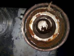
- Even at the very beginning, contamination can be found. We look for plaque visually in the inlet openings. We blow air into the part and also focus on the sound. We clean it if the exchanger is clogged. Pieces of scale may fall out of it even after a slight knock.
- You need to choose 1 of 3 cleaning options: home remedies like detergents and solutions with citric acid, special mixtures, or professional cleaning.
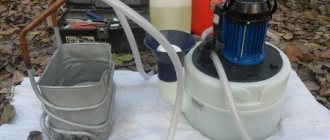
First of all, rinse the exchanger with a stream of water from a cold tap. Then pour citric acid into the device and place it in a bucket of water. Afterwards, take out the heat exchanger and pour water into it to check the permeability.
If it comes in slowly or does not move, then prepare a saturated solution of vinegar in water and pour it there. Then rinse with hot water and blow off. If possible, use an air pump. Do several cycles with vinegar.
Among the arguments for professional cleaning, it is worth noting the inconvenience of the design for cleaning, difficulties in assessing contamination, and the risk of damage due to independent mechanical action
If the steps described do not help, try special cleaning solutions: cleaning gel or low-percentage adipic acid solution. If this method does not work, then call a specialist or order professional cleaning.
Single-circuit or double-circuit boiler - is there a difference?
Varieties of boilers do not in any way affect the time period after which it is necessary to flush the heat exchanger. It is much more important which liquid (coolant) circulates in the heating system and which is supplied for hot water supply.
When using process water that has undergone standard purification, the boiler can be flushed no more than once every four years. This removes a layer of scale (which still forms) and deposits that have a more complex structure. If you do not filter water before pouring it into the system, but use ordinary water from a centralized water supply, then flushing should occur more often, at least once every two years. This is due to the high content of chlorine in the liquid, which, upon contact with the heating element, settles in the form of scale.
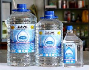
Distilled water is the best coolant option for permanent homes
Some users prefer to use antifreeze as a coolant. This liquid is of higher quality: it does not freeze even at low temperatures, releases heat more slowly, but heats up quickly. Unfortunately, antifreeze is poisonous , and breaking down into its components leads to damage to metal structures. The heat exchanger through which antifreeze circulates should be cleaned at least once every 1.5-2 years.
Therefore, both single-circuit and double-circuit boilers require timely cleaning of the heat exchanger, the intervals between which are the same in all systems.
In order to clean the bithermal heat exchanger less often, it is necessary to take care not only of the quality of the coolant in the heating circuit, but also of the quality of the water in the DHW system. The water should be pre-purified and filtered. You should also take into account the fact that the process of scale deposition begins at a temperature of 70°C, its rate increases by 2 times with every 10°C increase in temperature. In this case, the process progresses, since the growing layer of calcium impairs heat transfer and the temperature of the heat exchange wall increases.
Both circuits of the bithermal heat exchanger are subject to scale deposits
The process of replacing a heat exchanger with your own hands
To save money, many users decide to replace the heat exchanger in a gas boiler with their own hands. It’s worth noting right away that you shouldn’t try to solve the problem by soldering the hole that appears - this will extend the life of the heat exchanger by no more than 2-3 months. It is better to call a service center specialist or purchase a new circuit and perform the replacement yourself. The sequence of actions when carrying out repairs with your own hands is as follows:
- turn off the gas;
- disconnect the unit from electricity;
- disconnect the boiler from the water lines and prepare a bucket in case the remaining water leaks out;
- use a screwdriver to remove the unit cover;
- check according to the diagram in the instructions where the heat exchanger is located;
- disconnect the circuit and take it to the store to buy a new one, or immediately screw on a working element if available;
- connect the gas boiler to all previously disconnected communications;
- let in coolant to check the tightness of the system;
- If everything is normal, close the boiler body and screw in the removed bolts.
Replacing the circuit in a gas boiler with your own hands is quite possible, but it requires some accuracy and a clear sequence. If this manipulation seems too complicated, call a specialist - he will save you the unnecessary hassle of finding a suitable part, do everything quickly and provide a guarantee for his work.
Reasons for heat exchanger failure
The period of operation is determined primarily by how the water in the city water supply is disinfected. In Russia, either pure chlorine or chlorine dioxide is used. When the water flowing through the copper tube heats up, it causes a violent chemical reaction. Copper chloride is inferior to pure metal in strength, and therefore fistulas appear quite quickly. The luckiest people are residents of cities where tap water is ozonated.
Recommend: Heat Resistant Oven Sealant, High Temperature Chimney Sealant
But there are still very few such settlements. The high cost of the modern solution does not allow us to count on the rapid spread of ozonation. Moreover, now manufacturers have begun to save in every possible way. And if previously troubles happened quite rarely with thick tubes of heat exchangers, now thin, low-quality copper is used everywhere. The service life of products has significantly decreased.