Perpetual motion is found only in the works of science fiction. Any technical device, even of high quality, sometimes fails. Ariston boilers are convenient because error symbols are displayed on their LCD display, indicating a particular malfunction. The article will tell you how to interpret them correctly and give practical advice on how to fix the problem yourself.
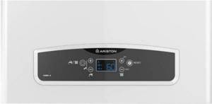
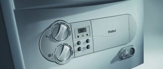
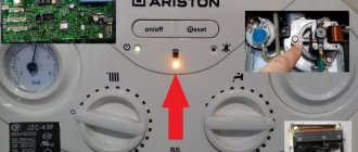
Ariston CARES X 24 FF control panel
Expert advice
- Before you begin repairing the Ariston boiler, you need to press the “RESET” button (translated as reset, playback, zero) and restart the heating installation. Often this helps restore its functionality. As a rule, the occurrence of an error is caused by voltage instability - a typical case in the private sector.
- If an Ariston boiler does not have a display and its indicator lights are blinking, it is not a fact that a malfunction has occurred. This happens when the Comfort mode is turned on. The heat generator is forced to adapt to the microclimate in the room, hence its periodic switching off/on
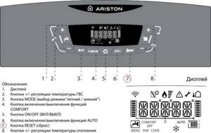
Ariston CARES X 24 FF control panel diagram with explanations
Organizing access to the hydraulic unit
Attention!
Before carrying out the operation, drain the water from the boiler.
Removing the pump pressure sensor
- Disconnect wires “W” from the sensor (Fig. 1.33);
- Unscrew the sensor using a wrench;
- Remove the sensor from the system.
Removing the safety valve
- Disconnect the unloading tube from below;
- Unscrew and remove valve “X” (Fig. 1.34).
Removing the air vent
- Unscrew the valve “Y” from the top (Fig. 1.35);
- Disconnect the valve assembly with the float (Fig. 1.36).
Dismantling the pump
- Disconnect the “Z” clamp (Fig. 1.37);
- Disconnect the clamps “A1” (Fig. 1.38);
- Loosen the nut “C1” (Fig. 1.39);
- Disconnect tube “D1” (Fig. 1.40);
- Unscrew the screws “E1” (Fig. 1.41);
- Remove the pump from the boiler.
Removing the pressure gauge
- Disconnect the clamp “F1” (Fig. 1.42)
- Disconnect the pressure gauge tube (Fig. 1.42);
- Push the pressure gauge out of the socket in the control panel by pressing it from the inside (Fig. 1.43).
Removing the expansion tank
- Loosen the nuts “G1” and disconnect the gas pipes (Fig. 1.44);
- Loosen the nut “H1” (Fig. 1.45);
- Unscrew the nut “I1” (Fig. 1.46);
- Remove the expansion tank from the boiler (Fig. 1.47).
Removing the overheating thermostat
- Disconnect the overheating thermostat wire “J1” (Fig. 1.48);
- Disconnect the thermostat from its mounting location by removing the clamp (Fig. 1.49 /1.50).
1.5.9 Removing the heating circuit temperature sensor
- Disconnect the connector and unscrew the sensor using a suitable wrench (Fig. 1.52).
You might be interested >> Features of plastic furniture production
1.5.8 Removing the DHW temperature sensor
- Disconnect the electrical connector and unscrew the sensor using a suitable wrench (Fig. 1.51).
1.5.10 Removing the DHW temperature sensor
- Disconnect the electrical connector “M1” (Fig. 1.59);
- Disconnect the clamp “N1” and remove the DHW temperature sensor.
Ariston error classification
All faults are displayed on the display with three-digit codes. The number in the first position indicates the problematic system (block, node).
1, 2 – OB or DHW circuit, respectively. 3 – control unit (Ariston boiler electronics). 4 – this group of symbols indicates problems with receiving information from external devices (room thermostat, sensors). 5 – lack of ignition, flame failure: codes related to the operation of the boiler burner. 6 – malfunctions in the smoke removal and air intake channels.
Deciphering Ariston errors
The number of codes displayed on the boiler display depends on the equipment modification. But there are errors that users most often encounter when using Ariston.
First group of codes
101. The sensor is triggered due to overheating.
Probable reasons:
• The error indicates insufficient coolant level.
Before filling the circuit, you need to check the system for leaks. It’s easy to visually identify by the puddles on the floor. • Airing. The error is typical for lines with heating radiators without an automatic air vent. • The filter or heat exchanger of the Ariston boiler is clogged. A decrease in flow rate causes error 101. • Problem with the circulation pump. Built-in pumping devices cannot be repaired - only replaced. There are options for a pump installed separately on a pipe. • Excessive gas supply to the Ariston burner. If “screwing” the valve does not produce results, you need to adjust the valve. 103–107 . Errors that directly indicate problems with coolant circulation.
Probable cause:
The result of air accumulation in the system.
Recommendations for Ariston models are somewhat different. • Boiler series Egis Plus 24. Press and hold the MODE button for at least 10 seconds. • Ariston UNO or Matis. Same for the RESET button. Short-term operation of the pump in the absence of ignition allows you to remove air from the system - the error disappears. 108. Critical decrease in pressure
Probable cause: leakage. It can appear in the expansion tank (connection point), heat exchanger, at pipe joints, in heating devices.
The error disappears after the defect is eliminated and the system is filled with liquid. 109 .
Excessive pressure This error is typical for Ariston boilers with a bimetallic (combined) heat exchanger. Probable cause: destruction of its internal partition (crack, fistula) leads to the flow of liquid from the water supply into the heating circuit.
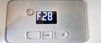
You need to start by bleeding the air in the system, and also drain some water. If over time the pressure increases and error 109 appears again, you will have to change the heat exchanger. 114–115 . The code “speaks” of problems with the external temperature sensor. Lack of contact - error 114, short circuit - 115. 117 . Appears on the display of the Ariston boiler series CARES X 24.
Ariston CARES control panel
Probable cause: low circulation of the environment. You need to press and hold the reset button (REZET) for about 10 seconds.
Second group of codes
201. The error appears when there is no signal from the DHW temperature sensor.
Probable reasons:
• Open circuit. The oxidized contacts are cleaned, the detached wire is soldered. • Sensor malfunction - replacement.
Third group of codes
302. This error is caused by a problem in the display-CU circuit. Mainly due to oxidation of contacts; After cleaning them, the code is not displayed. 303, 304 .
Malfunction of the Ariston boiler electronic board. Cannot be repaired independently - only replaced. The 304th error is displayed if pressing the REZET button repeatedly does not produce results. Recommendation: turn off the power to the boiler and turn on power after a while.
307 and 308 . When these codes appear, you can correct the situation by resetting the parameters. This error is evidence of a malfunction of the control board. If pressing the button does not help, the electronic unit of the boiler will have to be changed.
All other errors of the third group indicate internal failures in the control unit. Trying, for example, to “reflash the memory” yourself is not worth it.
Fourth group of codes
If errors appear with the number “4” in the first position, you should check all interfaces and sensitive elements (sensors) connected to Ariston.
Fifth group of codes
501. No boiler ignition.
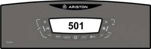
Displaying error 501 in the Ariston boiler
Probable reasons:
• The gas path is blocked.
Check the position of the shut-off valve handle on the pipe. • Incorrect position of the ionization sensor. The recommended interval between it and the burner comb is 8 mm. • Loose connection of the wire to the electrode. • Oxidized contacts. • Violation of the Ariston strapping rules. Initially, the boiler pipes are “plugged” with plugs (plastic, sometimes paper). Novice installers, without checking this, attach a water pipe. The error appears on the display due to the lack of flow - the valves do not operate, and the automation issues a signal prohibiting Ariston from being put into operation. 502 . Lights up when the ionization electrode gets wet. The recipe is simple - dry it. For example, a hairdryer.
Sixth group of codes
601. Insufficient traction or its complete absence. The error is typical for Ariston boilers equipped with an open combustion chamber.
Probable reasons:
• Change in direction and increase in wind speed.
This happens when you choose the wrong location for the chimney outlet from the house. Essentially, the boiler “blows out”. • The smoke exhaust duct is clogged. Garbage, foreign objects, even small birds falling into the pipe are the cause of the error. • Failure to follow the manufacturer's recommendations for the chimney layout. In this case, the 601st error appears during the initial start-up of the Ariston boiler. • Failure of the traction sensor - only replacement. 604 . Incorrect operation of the boiler fan (reduced shaft speed), malfunction of the Hall sensor. If the motor supply voltage is normal, internal defects are possible (axle misalignment, bearing destruction) - replacement. 607 . Problems with the fan (for supercharged Ariston versions).
Possible causes of the error:
• Relay malfunctions.
As a rule, it is associated with sticking contacts - replacement. • Malfunction of the boiler fan – similar. 608. The pressure switch did not work. At the same time, the Ariston fan blades rotate. Recommendation - checking and replacing a faulty sensor
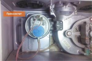
Placing a pressure switch in an Ariston boiler
Errors of individual modifications of Ariston
a01 – failure during ignition.
First of all, you need to check that the phases are connected correctly. For 220/1F boilers, it is enough to pull out the plug and insert it into the socket, turning it over 1800. As a rule, it helps to fix the problem. Probable causes: instability of the supply voltage, incorrect operation (or failure) of the boiler ionization sensor.
e34. The culprit” – pneumatic relay 108 – the pressure in the coolant system is below critical. sp2. The error appears after the second unsuccessful attempt to start the boiler.
Probable reasons: the gas line is blocked, a sharp drop in pressure in it, low pressure in the water supply.
H45 (or 54 ). An error is generated by the NTSc sensor. If there is a leak in the safety valve, it is enough to replace the seals. The serviceability of the sensitive element is determined by a multimeter - if the resistance at the contacts is unstable, it is rejected.
Access to the combustion chamber
Removing the combustion chamber front panel
- Unscrew the screws “E” (Fig. 1.10);
- Remove the combustion acme front panel.
Removing the burner and nozzles
| 1.3.3 Dismantling the electrodes Before carrying out this operation, unscrew and slide the burner forward (see previous section).
|
- Unscrew the screws “F” from the burner (Fig. 1.11);
- Disconnect the burner (Fig. 1.12);
- Disconnect the electrodes (see section 1.3.3
); - Unscrew the injectors using a socket wrench
7 mm;
- Reassemble in reverse order
Dismantling the heat exchanger
- Drain the water from the boiler;
- Remove the overheating thermostat, DHW flow sensor and heating temperature sensor “I” (Fig. 1.17);
- Loosen the 4 nuts “J”, which are attached to the heat exchanger of the coolant supply and return tube (Fig. 1.18);
- Remove the heat exchanger from the boiler (Fig. 1.19).
Reassemble in reverse order, paying attention to the following points:
a
—
Insert the electrode into the landing socket carefully, otherwise it may burst;
b –
Make sure that the left and right electrodes are installed correctly: they must face each other in order to ensure the required spark gap;
- –
Check that the wires are connected correctly; - –
Check that the rubber bushing completely covers the junction of the wire and the electrode. (Fig. 1.19)
Removing the differential pressure switch
- Disconnect the electrical connectors “N” and the silicone tube “O”
- Disconnect the connectors “K” of the silicone tubes
“L” (Fig. 1.20);
- Unscrew the screws “M” from the top of the combustion chamber
(Fig. 1.21);
- Disconnect the pressure switch (Fig. 1.22);
- Disconnect the relay from the mounting bracket.
Fan removal
- Disconnect the electrical connectors “N” and the silicone tube “O”
- Unscrew the screws “P” and remove the fan locking clamp “Q” (Fig.1.24);
- Unscrew the screws “R” (Fig.1.25);
- Remove the fan together with the mounting bracket from the boiler (Fig. 1.26).
Expert's conclusion
When stopping the Ariston boiler, you do not need to immediately call a technician and waste precious time. Just look at the code displayed on the display. Repair statistics show that in 85% of cases the user can solve the problem on his own. But you shouldn’t resort to the help of “all-knowing and experienced” people. Some Ariston models have significant design differences, which are taken into account during the repair process. The main advisor is the manufacturer's instructions. The document must have a section with explanations for each error code.