Formulas for calculating fan pressure
Pressure is the ratio of the acting forces and the area to which they are directed.
In the case of a ventilation duct, we are talking about air and cross-section. The flow in the channel is unevenly distributed and does not pass at right angles to the cross section. It will not be possible to find out the exact pressure from one measurement; you will have to look for the average value at several points. This must be done both for entering and exiting the ventilation device.
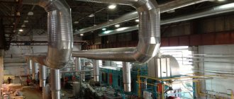
Axial fans are used separately and in air ducts; they work effectively where large masses of air need to be transferred at relatively low pressure.
The total pressure of the fan is determined by the formula Pp = Pp (out) – Pp (in), where:
- Pp (out) - total pressure at the outlet of the device;
- Pp (in.) - total pressure at the inlet to the device.
For fan static pressure, the formula differs slightly.
It is written as Rst = Rst (out) – Pp (in), where:
- Pst (out) - static pressure at the outlet of the device;
- Pp (in.) - total pressure at the inlet to the device.
Static pressure does not reflect the required amount of energy to transfer to the system, but serves as an additional parameter by which the total pressure can be determined. The last indicator is the main criterion when choosing a fan: both home and industrial. A decrease in total head reflects the loss of energy in the system.
The static pressure in the ventilation duct itself is obtained from the difference in static pressure at the inlet and outlet of the ventilation: Pst = Pst 0 – Pst 1. This is a secondary parameter.
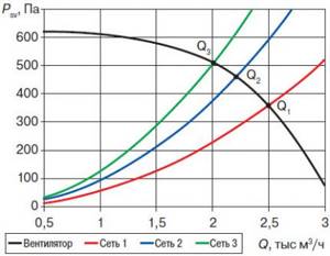
Designers provide parameters taking into account little or no blockage: the image shows the discrepancy in the static pressure of the same fan in different ventilation networks
The correct choice of a ventilation device includes the following nuances:
- calculation of air flow in the system (m³/s);
- selection of a device based on this calculation;
- determining the output speed for the selected fan (m/s);
- calculation of Pp device;
- measurement of static and dynamic pressure for comparison with total pressure.
To calculate the location for measuring the pressure, they are guided by the hydraulic diameter of the air duct. It is determined by the formula: D = 4F / P. F is the cross-sectional area of the pipe, and P is its perimeter. The distance to determine the measuring location at the inlet and outlet is measured by the number D.
Coolant in static and dynamic states
The coolant of any heating system can be in two states:
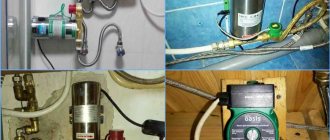
- stationary (static), when there is no heating in the gravitational system (no natural circulation) or the circulation pump is turned off in a system with forced circulation;
- mobile (dynamic), caused by the following reasons: natural circulation of the coolant, driven by a pressure gradient due to uneven heating of the working fluid along the contour of the gravitational heating system;
- forced circulation of coolant driven by a circulation pump;
- thermal expansion of the coolant, causing it to displace air/gas from the expansion tanks, occupying the vacated volumes.
The stationary coolant exerts only (hydro)static pressure on the internal surfaces of the system elements, which is studied by hydrostatics. A moving coolant is characterized by (hydro)dynamic pressure, studied by hydrodynamics. It consists of a static component, then a part determined by the thermal expansion of the liquid, and finally a component created by the so-called. high-speed pressure of a moving fluid. Further, when considering a moving heated coolant, we will use the term working (resulting) pressure.
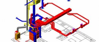
Calculation of air ducts for supply and exhaust systems of mechanical and natural ventilation
Aerodynamic calculation of air ducts usually comes down to determining the dimensions of their cross-section, as well as pressure losses in individual sections and in the system as a whole. It is possible to determine air flow rates for given duct sizes and a known pressure drop in the system.
When aerodynamically calculating air ducts for ventilation systems, the compressibility of moving air is usually neglected and excess pressure values are used, taking atmospheric pressure as a conditional zero.
When air moves through an air duct in any cross-section of the flow, three types of pressure are distinguished: static, dynamic
and
complete.
Static pressure
determines the potential energy of 1 m3 of air in the section under consideration (pst is equal to the pressure on the walls of the air duct).
Dynamic pressure
– this is the kinetic energy of the flow per 1 m3 of air, determined by the formula:
(1)
where is air density, kg/m3; – speed of air movement in the section, m/s.
Total pressure
equal to the sum of static and dynamic pressures.
(2)
Traditionally, when calculating a duct network, the term “pressure loss” (“flow energy loss”) is used.
Pressure losses (total) in the ventilation system consist of friction losses and losses in local resistance (see: Heating and ventilation, part 2.1 “Ventilation”, edited by V.N. Bogoslovsky, M., 1976).
Friction pressure losses are determined using the Darcy formula:
(3)
where is the friction resistance coefficient, which is calculated using the universal formula A.D. Altshulya:
(4)
where is the Reynolds criterion; K is the height of the roughness protrusions (absolute roughness). In engineering calculations, pressure loss due to friction, Pa (kg/m2), in an air duct of length /, m, is determined by the expression
(5)
where – pressure loss per 1 mm of air duct length, Pa/m [kg/(m2 * m)].
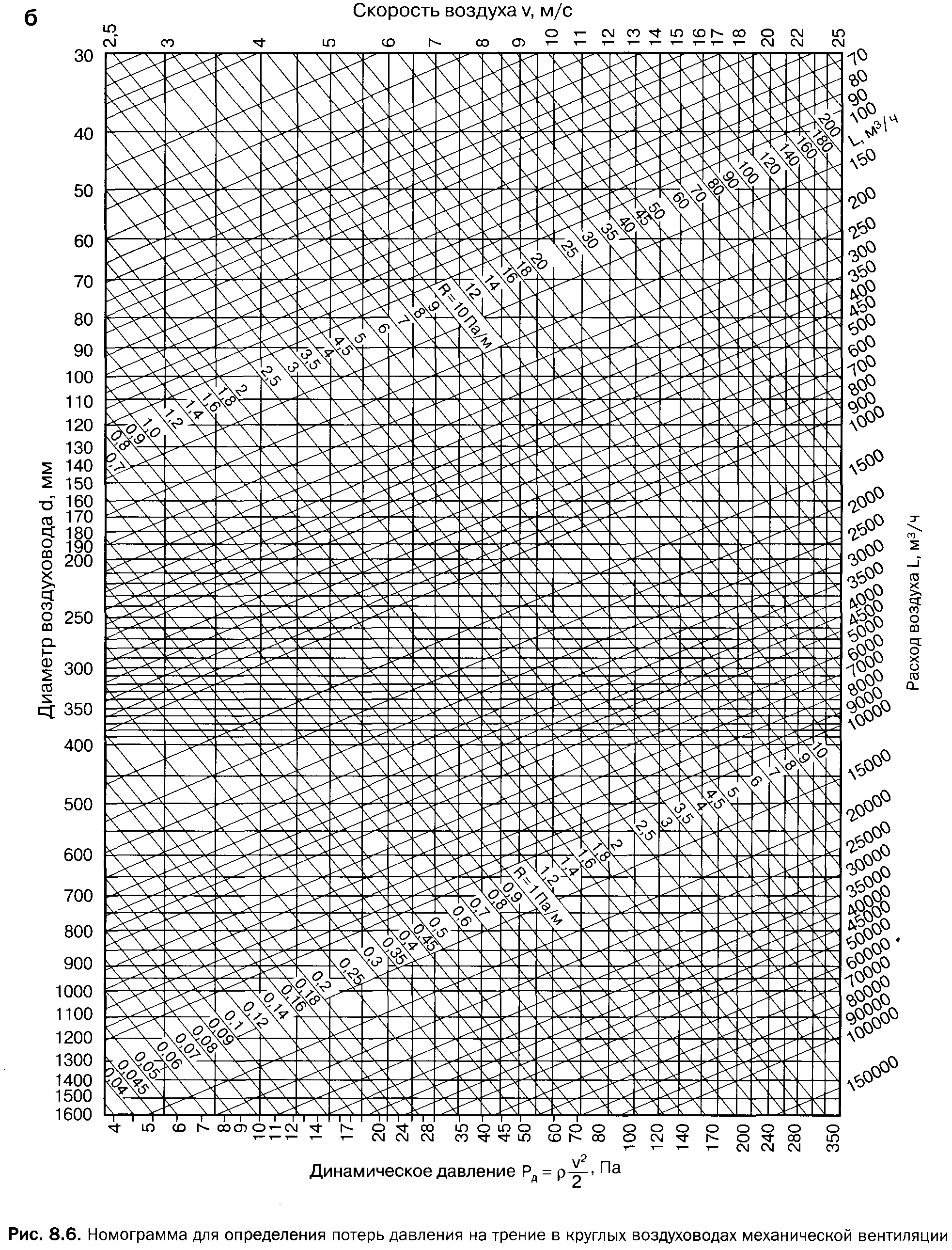
To determine R
tables and nomograms were compiled. Nomograms (Fig. 1 and 2) were built for the following conditions: the cross-sectional shape of the air duct is a circle with a diameter, air pressure 98 kPa (1 atm), temperature 20°C, roughness = 0.1 mm.
To calculate air ducts and channels of rectangular cross-section, use tables and nomograms for round air ducts, while introducing the equivalent diameter of a rectangular air duct, at which the pressure loss due to friction in the round and rectangular air ducts is equal.
In design practice, three types of equivalent diameters have become widespread:
■ by speed
with equal speeds
■ by consumption
with equal expenses
■ by cross-sectional area
with equal cross-sectional areas
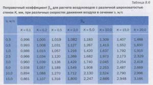
When calculating air ducts with a wall roughness different from that specified in the tables or nomograms (K = OD mm), an amendment is given to the tabulated value of specific pressure loss due to friction:
(6)
where is the tabulated value of specific pressure loss due to friction; – coefficient for taking into account the roughness of the walls (Table 8.6).
Pressure losses in local resistances. In places where the air duct turns, when dividing and merging flows in tees, when changing the size of the air duct (expansion - in the diffuser, narrowing - in the confuser), when entering and leaving the air duct or channel, as well as in places where control devices (throttles) are installed , dampers, diaphragms) there is a pressure drop in the flow of moving air. In these places, a restructuring of the air velocity fields in the air duct occurs and the formation of vortex zones near the walls, which is accompanied by a loss of flow energy. The flow evens out at some distance after passing through these places. Conventionally, for the convenience of aerodynamic calculations, pressure losses in local resistances are considered concentrated.
Pressure loss in local resistance is determined by the formula
(7)
where is the coefficient of local resistance (usually, in some cases, a negative value occurs; the sign should be taken into account in calculations).
The coefficient refers to the highest speed in the narrowed section of the section or the speed in the section of the section with lower flow (in the tee). The tables of local resistance coefficients indicate which speed it applies to.
Pressure loss in the local resistance of the section, z, is calculated using the formula
(8)
Where
– the sum of the local resistance coefficients on the site.
Total pressure loss over a section of air duct length, m, in the presence of local resistances:
(9)
where is the pressure loss per 1 m of air duct length;
– pressure losses in local resistances of the section.
Constant head loss method
This method assumes a constant loss of pressure per 1 linear meter of air duct. Based on this, the dimensions of the air duct network are determined. The constant pressure loss method is quite simple and is used at the stage of feasibility study of ventilation systems.
- Depending on the purpose of the room, according to the table of permissible air speeds, select the speed on the main section of the air duct.
- Based on the speed determined in paragraph 1 and based on the design air flow, the initial pressure loss is found (per 1 m of duct length). The diagram below does this.
- The most loaded branch is determined, and its length is taken as the equivalent length of the air distribution system. Most often this is the distance to the farthest diffuser.
- Multiply the equivalent length of the system by the pressure loss from step 2. The pressure loss at the diffusers is added to the resulting value.
- Now, using the diagram below, determine the diameter of the initial air duct coming from the fan, and then the diameters of the remaining sections of the network according to the corresponding air flow rates. In this case, the initial pressure loss is assumed to be constant.
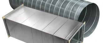
Using rectangular ducts
The pressure loss diagram shows the diameters of round ducts. If rectangular ducts are used instead, their equivalent diameters must be found using the table below.
Notes:
- If space allows, it is better to choose round or square ducts.
- If there is not enough space (for example, during reconstruction), rectangular air ducts are chosen. As a rule, the width of the duct is 2 times the height).
The table shows the height of the air duct in mm along the horizontal line, its width along the vertical line, and the cells of the table contain the equivalent diameters of the air ducts in mm.
Table of equivalent duct diameters
| Dimensions | 150 | 200 | 250 | 300 | 350 | 400 | 450 | 500 |
| 250 | 210 | 245 | 275 | |||||
| 300 | 230 | 265 | 300 | 330 | ||||
| 350 | 245 | 285 | 325 | 355 | 380 | |||
| 400 | 260 | 305 | 345 | 370 | 410 | 440 | ||
| 450 | 275 | 320 | 365 | 400 | 435 | 465 | 490 | |
| 500 | 290 | 340 | 380 | 425 | 455 | 490 | 520 | 545 |
| 550 | 300 | 350 | 400 | 440 | 475 | 515 | 545 | 575 |
| 600 | 310 | 365 | 415 | 460 | 495 | 535 | 565 | 600 |
| 650 | 320 | 380 | 430 | 475 | 515 | 555 | 590 | 625 |
| 700 | 390 | 445 | 490 | 535 | 575 | 610 | 645 | |
| 750 | 400 | 455 | 505 | 550 | 590 | 630 | 665 | |
| 800 | 415 | 470 | 520 | 565 | 610 | 650 | 685 | |
| 850 | 480 | 535 | 580 | 625 | 670 | 710 | ||
| 900 | 495 | 550 | 600 | 645 | 685 | 725 | ||
| 950 | 505 | 560 | 615 | 660 | 705 | 745 | ||
| 1000 | 520 | 575 | 625 | 675 | 720 | 760 | ||
| 1200 | 620 | 680 | 730 | 780 | 830 | |||
| 1400 | 725 | 780 | 835 | 880 | ||||
| 1600 | 830 | 885 | 940 | |||||
| 1800 | 870 | 935 | 990 |
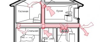
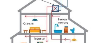
The importance of proper air exchange

The main purpose of ventilation is to create and maintain a favorable microclimate inside residential and industrial premises.
If the air exchange with the outside atmosphere is too intense, then the air inside the building will not have time to warm up, especially in the cold season. Accordingly, the rooms will be cold and not humid enough.
Conversely, with a low rate of renewal of the air mass, we get a waterlogged, excessively warm atmosphere, which is harmful to health. In advanced cases, the appearance of fungi and mold on the walls is often observed.
We need a certain balance of air exchange that will allow us to maintain humidity levels and air temperatures that have a positive effect on people’s health. This is a major problem that needs to be solved.
Air exchange depends mainly on the speed of air passage through the ventilation ducts, the cross-section of the air ducts themselves, the number of bends in the route and the length of sections with smaller diameters of air-conducting pipes.
All these nuances are taken into account when designing and calculating the parameters of the ventilation system.
These calculations make it possible to create reliable indoor ventilation that meets all standard indicators approved in the “Building Codes and Rules”.
Recommended rate
Calculating air speed yourself is not so easy. To do this, a complex formula is used, in which the main parameter will be the diameter and cross-sectional radius of the pipes, as well as the size of the ventilation grille. It is better to entrust the calculations to a specialist who can get the most accurate results.
It is worth noting that noise indicators play an important role, since if the norm is exceeded, it is necessary to increase the cross-section of the pipes. Sometimes the situation can be corrected by installing pipes made of a different material or eliminating one of the bends. The direct channel always reduces the indicator. When creating a building project, specialists take into account each site and make calculations.
Before installing the ventilation system, workers already know the dimensions of each pipe, length, width and direction, as well as the number of bends, without which it is almost impossible to install the structure. Even at the design stage of a building, experts take into account its purpose. After this, diagrams are drawn up based on the standards provided in a special document (SNiP).
It is believed that in a residential area the air speed in the air duct should not exceed 0.3 m/s. In the case of repair work, it is allowed to exceed this norm, but not more than 30%. In industrial premises with a large area, two ventilation systems are often used to increase the efficiency of air exchange.
Each of the systems does not operate at full capacity, since this reduces the efficiency of heating the room. In the event of a fire, one of the ventilation systems is forcibly stopped in order to reduce the air speed and prevent the fire of neighboring objects. It is for this purpose that special valves are installed, which can be closed if necessary.
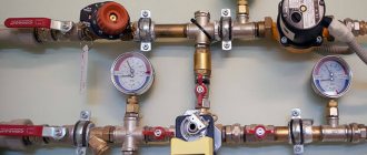
Adjustment
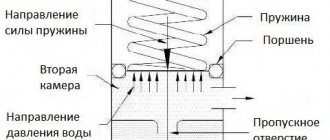
How to adjust the pressure in the elevator unit?
Support washer
To be correct, when using a retaining washer, it is not necessary to adjust the pressure, but to periodically replace the washer with a similar one due to abrasive wear of the narrow metal sheet in process water. How to replace the washer with your own hands?
The instructions are generally quite simple:
- All valves or valves in the elevator are closed.
- One vent on the return and supply is opened to drain the unit.
- The bolts on the flange are loosened.
- Instead of the old washer, a new one is installed, equipped with a pair of gaskets - one on each side.
Tip: in the absence of paronitis, washers are cut from a dilapidated car inner tube. Don't forget to cut an eyelet that will allow the washer to fit into the flange groove.
- The bolts are tightened in pairs, crosswise. Once the gaskets are pressed, the nuts are tightened until they stop, no more than half a turn at a time. If you rush, uneven compression will certainly lead to the gasket being torn off by pressure from one side of the flange.
Calculation algorithm
When designing, adjusting or modifying an existing ventilation system, air duct calculations must be performed. This is necessary in order to correctly determine its parameters, taking into account the optimal performance and noise characteristics under current conditions.
When performing calculations, the results of measuring the flow rate and speed of air movement in the air channel are of great importance.
Air flow is the volume of air mass entering the ventilation system per unit of time. As a rule, this indicator is measured in m³/h.
Movement speed is a value that shows how quickly air moves in the ventilation system. This indicator is measured in m/s.
If these two indicators are known, the area of circular and rectangular sections, as well as the pressure required to overcome local resistance or friction, can be calculated.
When drawing up a diagram, you need to choose a viewing angle from the façade of the building, which is located at the bottom of the layout. Ducts are shown as solid thick lines
The most commonly used calculation algorithm is:
- Drawing up an axonometric diagram that lists all the elements.
- Based on this scheme, the length of each channel is calculated.
- Air flow is measured.
- The flow rate and pressure in each section of the system are determined.
- Friction losses are calculated.
- Using the required coefficient, the pressure loss when overcoming local resistance is calculated.
When performing calculations on each section of the air distribution network, different results are obtained. All data must be equalized using diaphragms with the branch of the greatest resistance.
Calculation of cross-sectional area and diameter
Correct calculation of the area of round and rectangular sections is very important. An unsuitable cross-section size will not provide the desired air balance.
A duct that is too large will take up a lot of space and reduce the effective area of the room. If the channel size is too small, drafts will appear as the flow pressure increases.
In order to calculate the required cross-sectional area (S), you need to know the values of flow rate and air speed.
The following formula is used for calculations:
S = L/3600*V,
in this case L is the air flow rate (m³/h), and V is its speed (m/s);
Using the following formula, you can calculate the duct diameter (D):
D = 1000*√(4*S/π), where
S – cross-sectional area (m²);
π – 3.14.
If you plan to install rectangular rather than round air ducts, instead of the diameter, determine the required length/width of the air duct.
All obtained values are compared with GOST standards and products that are closest in diameter or cross-sectional area are selected
When choosing such an air duct, the approximate cross-section is taken into account. The principle is used: a*b ≈ S, where a is the length, b is the width, and S is the cross-sectional area.
According to regulations, the ratio of width to length should not be higher than 1:3. You should also use the standard size chart provided by the manufacturer.
The most common sizes of rectangular ducts are: minimum dimensions - 0.1 m x 0.15 m, maximum - 2 m x 2 m. The advantage of round air ducts is that they have less resistance and, accordingly, create less noise during operation.
Calculation of pressure loss due to resistance
As air moves along the line, resistance is created. To overcome it, the fan of the air handling unit creates pressure, which is measured in Pascals (Pa).
Pressure loss can be reduced by increasing the cross-section of the air duct. In this case, approximately the same flow rate in the network can be ensured
In order to select a suitable air handling unit with a fan of the required capacity, it is necessary to calculate the pressure loss to overcome local resistance.
This formula applies:
P=R*L+Ei*V2*Y/2, where
R – specific pressure loss due to friction in a certain section of the air duct;
L – section length (m);
Еi – total local loss coefficient;
V – air speed (m/s);
Y – air density (kg/m3).
R values are determined according to standards. This indicator can also be calculated.
If the duct cross-section is circular, the friction pressure loss (R) is calculated as follows:
R = (X*D/B) * (V*V*Y)/2g, where
X – coefficient. friction resistance;
L – length (m);
D – diameter (m);
V is the air speed (m/s), and Y is its density (kg/m³);
g – 9.8 m/s².
If the cross-section is not round, but rectangular, it is necessary to substitute an alternative diameter into the formula, equal to D = 2AB/(A + B), where A and B are sides.
Technical calculations are free and anonymous =)
- Heating Calculation of heat load based on aggregated indicators MDK 4-05.2004
- Collector diameter calculation
- Calculation of expansion tank for heating
- Calculation of the number of stages of the DHW heat exchanger
- Calculation of DHW heating
- Calculation of the length of compensators for thermal expansion of pipelines
- Calculation of water speed in a pipeline
- Dilution of propylene and ethylene glycol
- Calculation of the diameter of the balancing washer
- Checking the functionality of the elevator heating system
- kg/s to m3/h. Converting the mass flow rate of the medium into volumetric flow.
- Online replacement of Prado radiators with Purmo
- Examples of hydraulic calculations for heating systems
- Sanext Calculation of diameter and settings of Sanext DPV valve
- Calculation of the Sanext heating system floor collector
- Marking RKU Sanext
- Replacing Danfoss AB-QM valve with Sanext DS
- Quick replacement of L and T-shaped tubes with Stabil pipe
- Calculation of gravitational pressure
- Calculation of air conditioner power based on heat flow into the room
- Calculation of resistance in the VK pipeline
- Technical and economic calculation of heat and fuel
- Calculation of the painting area of a metal profile
- Technical unit converter
Calculation method
The most common option is when both parameters - pressure force and cross-sectional area - are unknown. In this case, each of them is determined separately, using its own formulas.
Speed
It is necessary to obtain dynamic pressure parameters in the designed area. It must be remembered that the air flow is known in advance, and not for the entire system, but for each section. Measured in m/s.
υ fak = L/(3600×Ff), where
L – air flow in the area under study, m3/h
Pressure
The ventilation system is divided into separate branches (sections) according to places where air flow changes or changes in cross-sectional area. Each one is numbered. Natural available pressure is determined by the formula:
Δre = h .g ( ρн –ρвн), where
h – difference in rise between the upper and lower points ρн and ρвн – density inside/outside
Densities are determined using the parameters of the temperature difference between the air inside and outside the room. They are specified in SNiP 41-01-2003 “Heating, ventilation and air conditioning”. Next comes the formula:
Σ(R . L .βш +Z) ≤Δ re, where
Σ(R . L .βш +Z) – the sum of the pressure flow in the area under consideration, where
R – specific friction losses (Pa/m); L – length of the section under consideration (m); βш – coefficient of roughness of the walls of ventilation ducts; Z – pressure loss in local resistances; Δpe – natural available pressure.
It is important to provide a small margin of pressure; 5-10% will be sufficient.
The selection of the air duct is carried out according to special tables. If a square or rectangular cross-section is required, then it is given according to the formula for the equivalent of a round channel:
deq = 2a. in /(a+b), where
a,c – geometric dimensions of the channel, cm
Step-by-step work with aerodynamic calculations in Excel
If you need to do an aerodynamic calculation, but you are not ready to calculate these colossal formulas by hand, then Excel can help.
The link contains an Excel file that can be downloaded or edited online. To get the result, you need to fill in only 6 columns of the table, and then the program will do everything itself. Let's take all the same offices for the reliability of the results. We introduce step by step:
- Air flow in each area.
- The length of each of them.
- Recommended speed. After filling, the file will already calculate the minimum required cross-sectional area.
- Based on the recommended area, you need to select the size of the air duct. Simply enter the height and width in column F and G, and the speed on the section and the equivalent diameter will be immediately calculated. As a result, the Reynolds number.
- The equivalent roughness is also entered manually.
- At each site, it will be necessary to calculate the amount of CMR and also enter it into the table.
- Enjoy the results of the calculations!
Let us recall that the aerodynamic calculation in Excel was made for rectangular steel air ducts at a supply air temperature of 20°C. If your parameters are different, replace the density, roughness and viscosity values with yours. The table fully complies with the calculation formulas and is ready for use. Successful aerodynamic calculations to you!!!
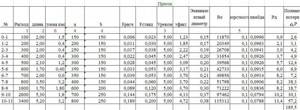
Ventilation system calculation form
Plot number (see Fig. 2.2)
P
D,
Pa Values of
R
are determined either from special tables or from a nomogram (Figure 3.2) compiled for steel round air ducts with diameter d
.
The same nomogram can also be used to calculate air ducts of rectangular cross-section a b
, only in this case the value
d
is understood as the equivalent diameter
d
e = 2
ab
/ (
a
+
b
).
The nomogram also shows the values of the dynamic pressure of the air flow corresponding to the density of standard air ( t
= 20 o C; φ = 50%; barometric pressure 101.3 kPa;
= 1.2 kg/m3). At density
dynamic pressure is equal to the scale reading multiplied by the ratio
/1,2
Fans are selected according to aerodynamic characteristics, showing the graphical interdependence of their total pressure, flow, rotation speed and peripheral speed of the impeller. These specifications are based on standard air.
It is convenient to select fans using nomograms, which are summary characteristics of fans of one series. Figure 3.3 shows a nomogram for selecting centrifugal fans of the Ts4-70 * series, which are widely used in ventilation systems of agricultural industrial buildings and structures. These fans have high aerodynamic properties and are silent in operation.
From the point corresponding to the found feed value L
c, draw a straight line until it intersects with the ray of the fan number (fan no.) and then vertically to the line of the calculated total pressure
fan
The intersection point corresponds to the fan efficiency
and the value of the dimensionless coefficient A
, which is used to calculate the fan rotation speed (min -1).
The horizontal scale of the nomogram shows the speed of air movement in the fan outlet.
The selection of a fan must be carried out in such a way that its efficiency is not lower than 0.85 of the maximum value.
Required power on the electric motor shaft to drive the fan, kW:
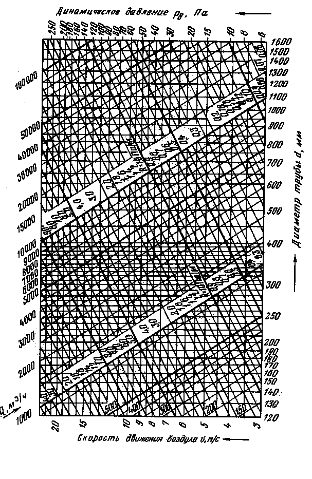
Fig. 3.2 Nomogram for calculations of round steel air ducts
Fig.3.3 Nomogram for selecting centrifugal fans of the Ts4-70 series
Stage three: linking branches
When all the necessary calculations have been carried out, it is necessary to link several branches. If the system serves one level, then branches not included in the main line are linked. The calculation is carried out in the same order as for the main line. The results are entered into the table. In multi-storey buildings, floor branches at intermediate levels are used for linking.
Linking criteria
Here the values of the sum of losses are compared: pressure along the linked sections with a parallel connected main line. It is necessary that the deviation is no more than 10 percent. If it is determined that the discrepancy is greater, then the linkage can be carried out:
- by selecting the appropriate cross-sectional dimensions of the air ducts;
- by installing diaphragms or throttle valves on the branches.
Sometimes all you need to make such calculations is a calculator and a couple of reference books. If you need to carry out an aerodynamic calculation of the ventilation of large buildings or industrial premises, then you will need an appropriate program. It will allow you to quickly determine the dimensions of sections and pressure losses both in individual sections and in the entire system as a whole.
https://www.youtube.com/watch?v=v6stIpWGDow Video can't be loaded: Design of ventilation systems. (https://www.youtube.com/watch?v=v6stIpWGDow)
The purpose of the aerodynamic calculation is to determine the pressure loss (resistance) to air movement in all elements of the ventilation system - air ducts, their shaped elements, grilles, diffusers, air heaters and others. Knowing the total value of these losses, you can select a fan that can provide the required air flow. There are direct and inverse problems of aerodynamic calculations. The direct problem to be solved when designing newly created ventilation systems is to determine the cross-sectional area of all sections of the system at a given flow rate through them. The inverse problem is to determine the air flow for a given cross-sectional area of operating or reconstructed ventilation systems. In such cases, to achieve the required flow rate, it is enough to change the fan speed or replace it with a different size.
By area F
determine the diameter D
(for a round shape) or height
A
and width
B
(for a rectangular) air duct, m. The resulting values are rounded to the nearest larger standard size, i.e.
D st
,
A st
and
B st
(reference value).
Recalculate the actual cross-sectional area F
fact and speed v fact
.
For a rectangular duct, the so-called equivalent diameter DL = (2A st * B st) / (A st + B st ), m.
Determine the value of the Reynolds similarity criterion
Re = 64100* D st * v fact.
For a rectangular shape
D L = D art.
Friction coefficient
λtr = 0.3164 ⁄ Re-0.25 at Re≤60000, λtr = 0.1266 ⁄ Re-0.167 at Re>60000.
The local resistance coefficient
λm
depends on their type, quantity and is selected from reference books.
Comments:
- Initial data for calculations
- Where to start? Calculation order
The heart of any ventilation system with mechanical airflow is the fan, which creates this flow in the air ducts. The power of the fan directly depends on the pressure that must be created at the outlet, and in order to determine the value of this pressure, it is necessary to calculate the resistance of the entire channel system.
To calculate pressure losses, you need a diagram and dimensions of the air duct and additional equipment.
Pressure in pipes of apartment buildings
From the contents of the previous sections, it becomes clear that the amount of heating in the central heating pipelines of high-rise buildings depends on the floor on which the apartment is located. The situation is as follows: if residents of the first two floors can roughly navigate using a pressure gauge installed in the basement heating unit, then the real pressure in the remaining dwellings remains unknown, since it drops with every meter of water rise.
Note. In new buildings with apartment-by-apartment heating distribution from a common riser, where floor-to-floor heating units are equipped, it is possible to control the coolant pressure at the entrance to each apartment.
Moreover, knowing the amount of pressure in a centralized network is of no practical use, since the owner cannot influence it. Although some people argue this way: if the pressure in the line has dropped, it means that less heat is supplied, which is a mistake. A simple example: turn off the return tap in the basement and you will see a jump in the pressure gauge needle, but the movement of water will stop and the supply of thermal energy will stop.
Let's sum it up
In conclusion, I would like to say that proper preparation of walls for future finishing work is almost of paramount importance. Especially when it comes to priming before puttying. Despite the common misconception that if the repair is cosmetic, then it is quite possible to get by with ordinary plaster, paint the walls or hang wallpaper without preliminary preparation and treatment of the surface of the walls - this is just another mistake of those who like to do everything “in a hurry”. The result of such negligence in relation to work that can be called art - repair - will be plaster falling off in pieces, mold and fungi crawling through the layers of paint and wallpaper, and the wallpaper will gradually slide to the floor or peel off in pieces.
Have you already guessed what the reason is? In the absence of a high-quality primer applied before applying putty.
Agree, it is better to do it once, but with high quality, and spend a couple of hundred rubles more than originally planned, but to do the work on the walls efficiently and for a long time, than in the future to spend money on repeated repairs, done once without proper attitude and responsibility.
You can pay 30-50% less for light, depending on what electrical appliances you use.