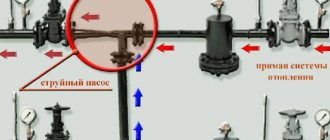
Steam systems often require different steam pressures. One steam generator can supply several consumers who require different coolant characteristics. In addition, for normal operation of the system, it is necessary to maintain a constant pressure in the main pipeline even with fluctuating steam flow, which is caused both by the needs of steam consumers and by its condensation. In order to meet all the conditions necessary for the operation of the system and maintain a constant reduction of steam, pressure regulators are installed on the steam line.
According to their purpose, the following pressure regulators are distinguished: pressure reducing valve (reducer or steam pressure regulator after itself), bypass valve (pressure regulator before itself), differential pressure regulator.
In this article, Andrey Shakhtarin, head of , will tell you what pressure regulators are, and in which cases, which one to install.
Types of water pressure regulators
There are five types of water pressure regulators:
- Flow-through:
- Membrane;
- Piston;
- Automatic;
- Electronic.
Based on the principle of installation and use, there are two types of regulators:
- Up to yourself;
- After myself.
The regulator “before itself” equalizes the pressure in the system located in front of it. Such regulators are used where it is necessary to protect the pipeline and plumbing fixtures from water hammer and high pressure. For example, in heating and cooling systems.
The water pressure regulator “after itself” equalizes the water pressure at the outlet. Such regulators are used where water is supplied to the end consumer:
- In the water supply system in the apartment;
- Irrigation systems;
- Wells, pumps, pump rooms;
- Water supply for technical needs.
As for the materials from which water pressure regulators are made, they can be:
- Cast iron;
- Steel;
- Brass;
- Titanium.
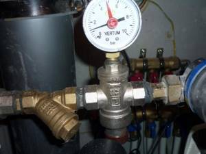
They also differ in configuration. Options may include:
- Pressure gauge;
- Mechanical cleaning filter;
- Ball Valves;
- Spare set of gaskets;
- Air vent.
How does a standard regulator work?
The operating principle of the regulator is quite simple to understand .
Water, with its pressure, activates the internal valve, moving it. The shutter of the device maintains its position thanks to the built-in spring. If the water pressure increases, the internal spring is compressed, causing the valve disc to move towards the reducer seat, thereby reducing the water pressure.
If the water pressure has decreased or was initially insignificant, the regulator valve opens and releases flow in the pipeline.
An equally important function of the gearbox is protection against water hammer, which can damage heating devices.
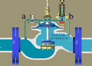
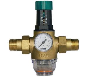
The principle of operation of a membrane water pressure regulator after itself
This pressure regulator consists of the following parts (see figure):
- A – Valve inlet;
- B – Valve output;
- C – Connection to the membrane chamber;
- D – Membrane chamber;
- E – Spring;
- F – Locking disc.
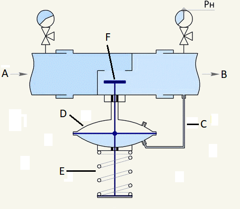
“Afterwards” water pressure regulator device.
It works like this:
- When the water pressure after the locking disc increases, it fills the membrane chamber;
- As the membrane chamber fills, the membrane presses on the rod connected to the locking disc;
- The disc closes the hole in the valve and the pressure after the valve decreases.
As the pressure decreases, the following happens:
- Water from the membrane chamber returns to the valve through the pipe;
- The pressure in the chamber decreases, the spring pulls back the locking disc;
- The flow of water through the hole in the valve increases and the pressure rises.
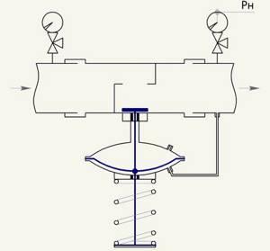
The principle of operation of the water pressure regulator after itself.
Types installed in the water supply system
There are several main types of devices in the pipeline system:

Piston. The pressure in it is controlled by pistons that open or close the valve of the device.
The device is regulated using a valve. Used in conjunction with cleaning filters. Without them, debris falling under the piston will break the gearbox from the inside.
- Membrane. The device is equipped with a spring-loaded membrane that controls the water pressure in the system. The regulator has holes on both sides for mounting a pressure gauge. Due to the absence of rubbing elements, diaphragm gearboxes are considered the most durable.
- Flow-through. The main positive feature of this device is the absence of moving parts. Water pressure is reduced by splitting the flow. The device is mounted together with an additional regulator for additional protection.
Most RDVs are supplied with ball and air valves, as well as water purification filters. In industry, devices with a throughput capacity of 20 cubic meters or more are installed. In everyday life, 3-5 cubic meters is enough.
How does a membrane water pressure regulator work?
The design of a water pressure regulator upstream is more complex than one that operates on the downstream principle. It consists of (see figure):
- A – Valve inlet;
- B – Valve output;
- C – Branch pipe from the valve inlet to the pilot regulator;
- D – Branch pipe from the membrane chamber to the valve outlet;
- E – Pilot regulator;
- F – Membrane chamber;
- G – Locking disc.
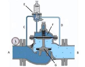
The water pressure regulator device is up to you.
The principle of operation of the water pressure regulator can be divided into two stages: increasing the pressure and decreasing it. When the valve inlet pressure increases, the following occurs:
- Water flows through the pipe from the inlet to the valve into the pilot regulator, where it presses on the spring;
- The pilot regulator opens the hole between the membrane chamber and the pipe to the outlet of the valve;
- Water leaves the membrane chamber, the spring pulls back the locking disc;
- The pressure at the valve inlet decreases.
When the pressure at the valve inlet decreases, the following occurs:
- Water from the pilot regulator is returned through the pipe to the valve inlet;
- The pilot regulator spring expands and the hole between the membrane chamber and the pipe to the valve inlet opens;
- The membrane chamber is filled with water and the locking disc closes the hole;
- The pressure at the valve inlet increases.
The principle of operation of the water pressure reducer.
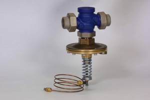
How are regulators arranged? Design features
Danfoss APT, DN32, article number - 003Z5704.
There are two types of regulators that have fundamental differences:
- The operation of the direct-acting does not require an additional energy source, since the fluctuations are controlled based on the indicators of the water masses. In this case, the valve opens at the moment of a certain discrepancy with the optimal pressure parameters. This process is carried out at a speed corresponding to the speed of parameter changes occurring in the system.
- Indirect-acting regulators can only operate if there is a separately connected power source. The function of measuring elements in such devices is performed by two sensors, through which a signal is transmitted towards the controller. In turn, the control device generates a signal sent to the control valve.
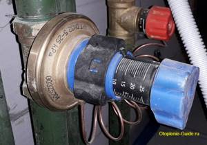
Danfoss ASV-PV, DN20, article number - 003Z5501.
The automatic direct-acting differential pressure regulator consists of:
- a set point device, which is played by a spring. Some devices are equipped with pneumatic mechanisms or lever-type devices;
- two impulse lines located directly under the valve body itself or built into the pipes;
- meter in the form of a membrane. In some cases, a bellows or piston element is used.
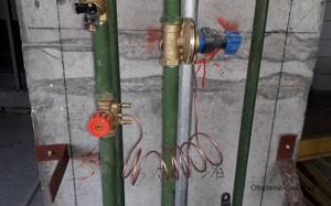
Danfoss ASV-PV, DN15.
Regulator valves are divided into unloaded and unbalanced. In addition, they come in both single and double saddle versions. Moreover, any of these devices can be connected to the pipeline via a threaded or flanged connection, as well as by welding pipes.
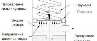
Piston water regulator: operating principle
In a piston regulator, the balance of incoming and outgoing pressure is achieved by a spring pushing the piston (see figure below). It works like this:
Water enters the first chamber, from which it passes into the second through an opening. When the pressure in the second chamber increases, it pushes the piston, which compresses the spring. The locking disc closes the passage hole and the pressure in the second chamber decreases.
When the water pressure decreases, the pressure in the first chamber decreases. The spring pushes out the piston and locking disc. Through the passage hole, water enters the second chamber and the pressure increases.
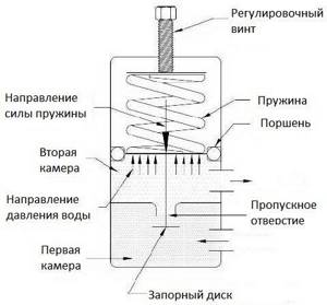
The device of a piston water pressure regulator.
The flow force can be adjusted by moving the spring and piston through the second chamber. For this purpose, such devices have an adjusting screw. By tightening it, you reduce the outlet pressure, and by unscrewing it, you increase it.
Operating principle of the differential pressure regulator
Currently, membrane-type regulators are predominantly used. Inside such a device there is a chamber with a centrally installed membrane, which is connected to the valve shutter. Due to its displacement to either side, the position of the shutter changes, as a result of which the amount of water masses flowing through the regulator is reduced or increased. The impact on the membrane is carried out through two impulse lines, through which signals are received coming from the supply pipe and the return pipe. The spring, which responds to different pressures, is compressed, thus acting on the membrane, which occupies a certain position.
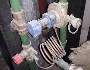
Danfoss ASV-PV, DN25.
How does an automatic pressure regulator work?
In its operating principle, an automatic regulator is similar to a piston regulator. The only difference is that the membrane acts as a piston (see figure), and the damper is spring-loaded.
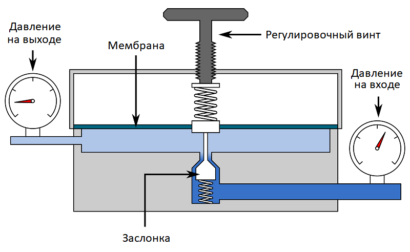
Automatic membrane pressure regulator device.
When the pressure of incoming water increases, it pushes the membrane upward. It pulls the flap and the hole is partially blocked. In this case, the pressure of the outlet flow decreases.
As the pressure of the incoming flow decreases, the membrane moves down, lowering the damper. The duct opening opens more and the outlet pressure increases.
A distinctive feature of automatic diaphragm valves is the presence of a second spring on the damper. It allows you to more accurately regulate pressure. The required outlet pressure is adjusted using the adjusting screw.
Types of regulator designs
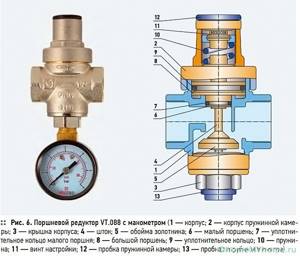
There are three design types of regulators:
- Piston
They are distinguished by their simplicity of design and low price, therefore they are the most common. A spring-loaded piston located inside closes the passage hole of the pipeline. This ensures constant outlet pressure. The control range is within 1-5 atm.
The piston does not wear out, which significantly increases the service life of such a device.
The disadvantage of this type of design is the moving piston, which requires only filtered water to be supplied at the inlet. The second disadvantage is the rapid wear of moving parts that limit the maximum flow of water.
Corrosion may occur on internal surfaces.
- Membrane
Flow regulation occurs due to the action of a spring-loaded membrane located in a separate, isolated chamber. The membrane opens and closes the control valve.
The internal cavity is divided by a membrane into two zones. One is in contact with water, and the other is well insulated. Thanks to this, dirty water does not flow through the membrane layer.
The design is reliable and unpretentious. The diaphragm regulator has rust protection inside. If used correctly, no maintenance is required.
Characterized by a wide pressure control zone and proportionality. It is possible to control the flow rate from 0.5 to 3 m3/hour.
The disadvantage is the appearance of cracks, ruptures and delamination on the membrane after a certain period of operation. Therefore, regular monitoring of the membrane condition is necessary.
Has a higher cost.
- Flow-through
The labyrinth in the middle of the body allows for dynamic pressure adjustment. Flow speed decreases when passing through divisions and many turns.
The regulator is installed in networks for irrigation and watering. There are no moving mechanisms in it, so parts made of plastic materials are used.
Before regulators of this type, additional installation of a valve or regulator in the inlet section is required. The operating control range of the device is 0.5-3 atm.
The flow regulator has a low cost.
- Electronic
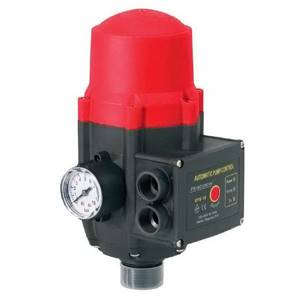
An electronic device ensures that a low-power pump is turned on when water is drawn from the network.
The design includes a housing, a diaphragm, boards, and connectors for connection. The regulator is equipped with a sensor to protect against water hammer and start pumping equipment “dry”.
The device operates silently.
The electronic device should be installed up to the first fence line. Underwater connections provide convenient integration into the pipeline. Before starting, the pump tank is filled with water.
The factory setting of the electronic regulator is 1.5 bar. Adjust the starting pressure value using a special screwdriver, taking into account that the nominal value should exceed the starting pressure by 0.8 bar.
Operating parameters of regulators:
- Maximum maximum pressure to ensure long-term operation. The parameter is regulated by GOST 26349-84.
- The value of the nominal diameter in accordance with the nominal diameter = m of the water supply system (GOST 28338-89).
- The throughput of the device, when the established control limits are maintained, in m3/hour.
- Operating range of regulation.
- The temperature range of operation of the device, which affects the ability to operate in heating and hot water supply lines, as well as at low air temperatures.
Electronic regulators
At the moment, these are the most advanced and accurate devices. They can work in modes before and after themselves. Their operating principle is as follows:
- A sensor at the inlet and outlet determines the water pressure;
- Signals from the sensors enter the control device;
- The device activates the locking mechanism or regulates the operation of the circulation pump.
Electronic water pressure regulators allow you to set the settings as accurately as possible. Due to this, they are used in systems designed for specific needs. But their cost is also high.
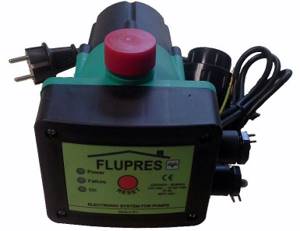
Electronic water pressure regulator.
Application area
Modern differential pressure regulators are most often used in water heating systems with hydraulic mode. The presence of such a device allows you to achieve the most stable pressure in the pipes involved in the operation of the heating network. If the device is installed correctly, the heating equipment will be reliably protected from zero flow associated with a system restart.
Danfoss ASV-PV, DN15.
Automatic regulators require virtually no maintenance. With relatively simple manipulations associated with setting up devices, they are able to maintain the specified parameters with fairly high accuracy.
Choose wisely
When choosing a water pressure regulator, you need to pay attention to the following:
- Maximum operating pressure of the device (it should be 20-30% higher than the maximum in the system);
- The diameter of the inlet and outlet must exactly match the diameter of the system pipes;
- The larger the pressure adjustment range, the better, but it is worth taking into account the features of the heating or water supply system;
- Before you settle on a type of regulator, make sure it will suit your needs. The option that is suitable for a water supply system cannot always be used in a heating system;
- When choosing an electronic regulator to connect to the circulation pump, check their compatibility.
Why adjustment is needed
First, let's find out what the pressure in the water supply should be.
Standard values
SP 30.13330.2012 gives a completely unambiguous answer to this question: at water collection points it should be within the range of 2 - 4.5 kgf/cm2.
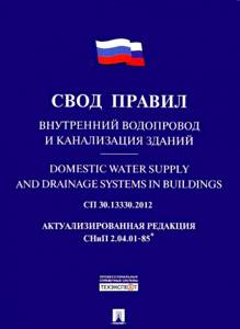
This document regulates the design and construction of internal water pipelines
Exceptions are allowed in two cases:
- The upper level can be raised to 6 kgf/cm2 if a low-rise building is being built in a multi-storey building;

A private house is connected to a common water supply line with multi-storey buildings
Reference: the atmosphere of excess pressure raises the water column to a height of 10 meters. For example, to supply water to the 10th floor of a building with a ceiling height of 2.7 meters (taking into account the thickness of the ceiling, each floor will have a total height of 3 meters), its minimum pressure should be 3*30/10=3 atmospheres.
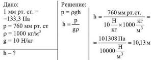
One atmosphere corresponds to a pressure of 10 meters
- The minimum pressure can be reduced to the value established by the manufacturers of the used plumbing equipment and household appliances using water. As a rule, the technical documentation for this equipment sets the lower limit at 0.3 kgf/cm2, which corresponds to a pressure of 3 meters.
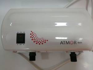
Atmor instantaneous water heater operates at a pressure of 0.3 - 6 kgf/cm2
And now we have to figure out why we need to regulate the pressure inside the building and why water is not always supplied to the water supply with the required pressure.
Low pressure
The reason for the lack of pressure can be:
- Overgrowing of steel pipes with deposits and rust. Over 10-15 years of operation, the throughput of a black steel pipeline may well decrease by 2-4 times. Not only that: as the internal cross-section narrows, the roughness of the walls increases, which again increases the hydraulic resistance of the water supply line;
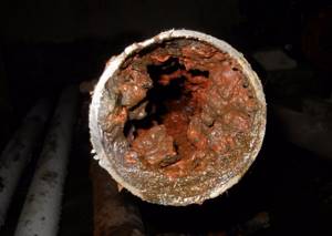
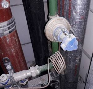
Typical condition of a steel pipe for cold water supply
Please note: not only main water pipelines suffer from deposits, but also steel bottlings, risers and liners. Increasing the water pressure solves the problem only for a while. A radical way to combat the decline in water supply capacity is to use modern corrosion-resistant materials (copper, stainless steel, polymer and composite pipes).
Polyethylene water supply does not rust or become overgrown with deposits
- Construction of multi-storey buildings in low-rise buildings without installation of booster pumping stations;
- Increasing the number of water consumers (read: connecting new buildings to the existing main water supply). In this case, as with overgrowing of pipes, a drop in water pressure is observed during peak discharge periods (usually in the morning and evening hours).
If the cross-section of the water supply is insufficient, interruptions in water supply occur during its peak flow
High pressure
When installing water supply in high-rise buildings, the problem of excessively high pressure on the lower floors arises.
Imagine a house 25 floors (75 meters) high. In order for the excess pressure in front of the mixer to be equal to two atmospheres on the top floor, at the level of the first floor it should be 2+(75/10)=9.5 kgf/cm2, which obviously exceeds the standards established by SP 30.13330.2012.
There are three possible solutions to this problem:
- Installation of intermediate pressure-increasing pumping stations in the middle of the building;
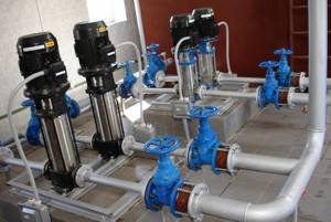
Boost pumping station
However: the layout of many buildings excludes the allocation of technical premises on intermediate floors. In addition, the noise of the pumps will disturb residents.
- Water supply to the upper and lower floors through different risers. In this case, a group of risers supplying the upper floors is served by a booster pump;
Please note: the disadvantage of this solution is the increased material consumption of the water supply system.
- Supplying water to risers with obviously excess pressure, and installing reducers at the entrances to apartments and other premises. Water supply pressure regulators will limit it in the internal water supply to values of 1-4.5 kgf/cm2, regardless of the pressure in the bottlings and risers. This is exactly the scheme that the notorious set of rules SP 30.13330.2012 prescribes for use in multi-storey buildings.
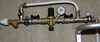
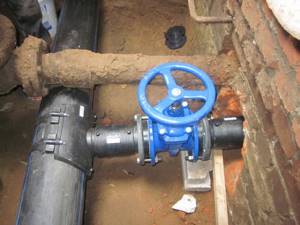
The water supply inlet is equipped with a reducer
A special case
In buildings built before the mid-70s of the 20th century, the hot water supply was dead-end: the water in the hot water taps and risers was renewed only when it was disassembled through taps.
This scheme has a number of rather unpleasant disadvantages:
- With a large bottling area, it is difficult to ensure that the water temperature at all water intake points meets regulatory requirements. As you move away from the heating point, it will decrease due to heat loss;
Reference: the standard water temperature in the hot water system is 60-75°C. It should be measured directly on plumbing fixtures.
- If there is no water supply for a long time, it has to be drained for a long time before heating;

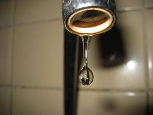
The problem of buildings with a dead-end hot water supply is the long drainage of cooled water in the morning
Meanwhile: mechanical water meters in apartments record water flow, not its temperature. You drain cold water, but pay for it at a much higher rate for domestic hot water.
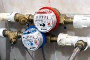
The meter records water consumption regardless of its temperature
- Heated towel rails only heat up when water is used. Hence the low temperature, dampness and mold in the bathrooms.
The DHW circulation system is free of all these disadvantages.
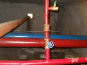
Sign of circulating DHW - two hot fills
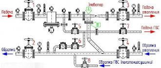
However, water circulation requires a pressure difference. When connecting hot water supply according to the “from supply to supply” or “from return to return” schemes, the difference can be created by throttling washers or a differential pressure regulator, which maintains its constant value for any changes in pressure in the heating network pipeline.
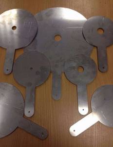
Throttle washers are placed on the flange between the hot water taps
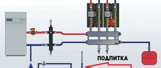
Differential pressure regulator: the building's water supply operates at a constant circulation rate, regardless of the parameters of the heating network
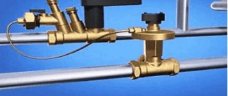
Correct installation of the water pressure regulator
Installing the pressure regulator is easy. When installing it or inserting it into the system, everything is done in the same way as when installing any plumbing fixture or shut-off valve. But there are certain rules that you should know.
In the apartment
Installing a water pressure regulator in an apartment requires compliance with the following rules:
- The regulator must be installed at the entrance to the heating system and regulate the pressure “after itself”;
- Before and after the regulator, it is necessary to install (if they are not present) ball valves in case of need for dismantling;
- Be sure to install a coarse filter in front of the regulator;
- If a conventional or automatic air vent is installed, the regulator must be located after it.
- Strictly observe the direction of water flow;
- Do not install the water pressure regulator “upside down”;
- The closer the regulator is to the riser, the better.
In a private house
When installing a pressure regulator in a private home, consider the following:
- You should be able to dismantle the regulator - install ball valves in front of it and after it;
- The pressure regulator “before itself” is installed in front of the pump, “after itself” - behind the pump;
- If the system does not have a coarse filter, install it in front of the regulator and circulation pump;
- If it is not water that circulates in the system, but a coolant, make sure that it will not damage the mechanisms and gaskets of the device, read the specification for the coolant;
- Observe the direction of flow when installing the regulator;
- Do not install the device upside down.
Why is it needed and how does the RDV work?
Water is supplied to both the centralized and autonomous systems by pumping equipment. Fundamentally, these schemes differ only in the number of branches, the diameter of the pipes and the number of shut-off valves. And pressure surges due to various technical reasons are possible in any of them. The water pressure regulator in the water supply system stabilizes the pressure and dampens the hydraulic shocks that occur in it.
In autonomous systems it is installed at the entrance to the house, in front of the meter, in centralized systems - in front of the apartment wiring. Such a mechanism will not hurt in private houses connected to a centralized water supply, despite the fact that there is a common water supply.
Regulator functions
The mechanism, which is also called a pressure reducer, acts as a stabilizer in the household water supply network. Without it, equipment designed for a certain pressure and responding to its changes fails faster. This applies not only to household appliances that consume water, for which water hammer becomes a serious test. But also electric boilers, gas water heaters, boilers, water meters.
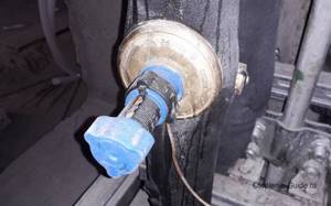
When the gearbox cannot be built into the beginning of the intra-house network, it is installed directly in front of the washing machine or other expensive equipment Source www.rmnt.ru
The pipelines themselves, especially the junctions and joints, also suffer from water hammer. With frequent pressure surges, they lose their tightness and begin to leak.
There is another reason why it is advisable to use a water reducer: it is convenient to use water dispensing devices. It’s not pleasant when a stream from a tap or shower head with adjusted temperature and pressure suddenly begins to randomly change these parameters.
Operating principle
Despite its modest size and simple design, the RDV copes with pressure regulation independently, without connecting additional equipment. And it does this automatically.
The principle of its operation is similar to how the flow of water is regulated by a valve tap, when unscrewing it the rod and piston rise and open a lumen of a certain cross-section. But in this case, as the pressure in the system increases, the piston remains motionless, and the force of the water flow increases. Whereas the water pressure valve in the reducer in such a situation changes its position and reduces the clearance.
At the outlet of the device, the pressure drops to the values set by the settingSource i.ytimg.com
We will trace the entire path of water through a system equipped with an RDV.
Water is supplied to the house from a well, a well or a centralized system using pumps that set a certain pressure.
Due to a pump malfunction, the tap on a branch being closed, or for some other reason, the pressure changes sharply, which threatens the equipment connected to the network with failure.
Passing through the reducer, the flow of water puts pressure on its operating element, which contracts and automatically reduces the clearance of the valve.
Changing the flow area does not allow water to move with the same pressure; it decreases and the water leaving the reducer flows to the points of consumption with standard pressure indicators.
In houses with water supply from a well or well, a hydraulic accumulator is often installed, equipped with a similar mechanism - a pressure switch. This device operates from an electrical network and is designed to turn on the pump when the pressure in the hydraulic tank drops, and turn it off when the specified parameters are reached. In this case, a water pressure reducer in the water supply system is not necessary, since the pressure will not exceed the maximum values set for the accumulator.
Autonomous water supply system with hydraulic accumulatorSource cdn.sovet-ingenera.com
But the pressure in the pipes will change within the limits specified by the relay. If the maximum pressure set for the hydraulic tank is more than 3 atmospheres, and for normal operation of household appliances it must be lower, then a regulator should be installed.
How to choose a device size
The initial data for selection are the following factors:
- Desired accuracy in instrument readings.
- Minimum overall dimensions of the space in which installation is intended.
- External operating conditions.
- Required speed.
- Equipment requirements.
- The complexity of routine maintenance.
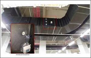
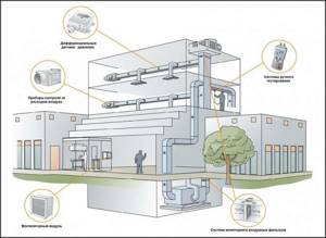
The general design of the ventilation system of a public or industrial building is quite complex and includes the use of devices for various purposes.
They require a wide range of pressure limits, typically from 2500 Pa to 250 Pa, with occasional requests up to 25 Pa. Traditional sensor products support only one calibrated full scale range to maintain the required sensor performance, requiring the use of 3-5 or even more separate systems to cover the required range of monitored quantities.
Therefore, in practice, proposals that allow one system to cover the entire required range while maintaining optimized calibrated air property variations are advantageous. With these devices, a variety of sensors can be optimized while maintaining industry-leading performance levels. Such devices, although specific for certain purposes, allow consumers to reduce the number of independent components in the ventilation system by 3...5 times or more, significantly saving on the cost of materials and energy resources. Installation and maintenance are also simplified.
Thus, to solve the assigned problems, the devices in question must ensure operation in the air pressure range from 25 to 2500 Pa, be connected to at least 3...5 calibrating devices, and provide the possibility of remote maintenance.
It is important to have multiple systems in place equipped with the sensors in question, allowing the user to change measurement ranges as needed. This balances indoor airflow and optimizes performance for each individual building duct system.