Functional features of a balancing valve for a heating system
Main balancing valve
The automatic balancing valve for the heating system for the main network differs from the radiator design in dimensions, spindle angle and fitting geometry.
Automatic balancer functions:
- Drainage of water from the heating system;
- connecting sensors to measure coolant parameters;
- installation of a pulse volute tube from a pressure corrector.
The number of turns that the balancer is capable of performing is from 3 to 5; this figure varies among most manufacturers. In order to change the position of the rod, you will need a wrench with a hexagon configuration. The adjustment is carried out based on the pressure difference in the heating network. During the setup process, when the flow rate of circulating water changes, the pressure loss in the pipeline and control valve also changes, which in turn leads to a change in the differential on the balancer.
The pressure drop in the network can be determined independently from the readings of pressure gauges installed on the return/supply of the in-house heating system. For example, with a supply/return pressure of 2.5 / 2.0 bar, the difference will be 2.5 – 2.0 = 0.5 bar. When the valve is automatic, it sets the differential itself according to the algorithm established by the design.
It should also be noted that not all heat supply systems require balancing. For example, if there are up to three short dead-end branches in the in-house wiring, equipped with 2 devices on each, their operation can be configured using ball valves or conventional shut-off and control valves.
Design and operating principle
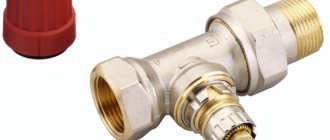
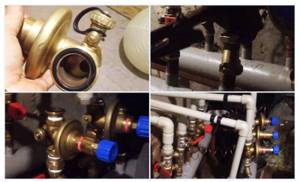
The radiator tap, designed for manual balancing of heating, consists of the following parts:
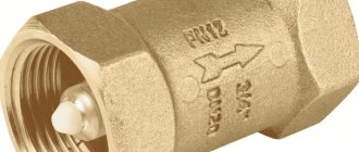
- Brass body with threaded pipe connections. Inside, a saddle is made using the casting method - a vertical round channel, slightly widening towards the top.
- A shut-off and regulating spindle with a working part in the form of a cone, which enters the saddle when twisted and limits the flow of water.
- O-rings made of EPDM rubber.
- Protective plastic or metal cap.
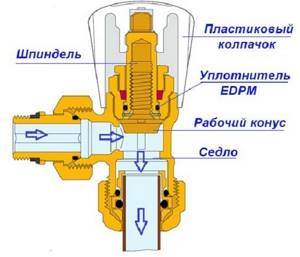
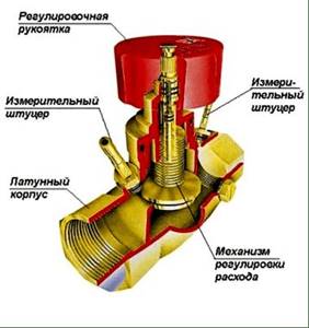
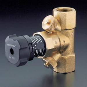
The figure shows a valve from Caleffi (website – https://www.caleffi.com)
Note. All well-known manufacturers - Danfoss, Herz, Caleffi and others - offer 2 types of valves - straight and angular. The principle of operation is the same, only the shape changes.
The device of the balancing valve is shown in more detail in the diagram above. It shows that rotation of the spindle leads to an increase or decrease in the flow area, and this is how the adjustment is made. The number of revolutions from the closed to the maximum open position is from 3 to 5, depending on the valve manufacturer. To turn the rod, you need to use a regular or special hex key.
Main taps differ from radiator taps in size, inclined position of the spindle and fittings designed for:
- coolant drain;
- connecting measuring instruments;
- connecting the capillary tube from the pressure regulator.
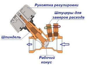
Main valve device for balancing heating branches
For reference. Radiator valve models, for example, from the Oventrop brand, are also equipped with a drain pipe.
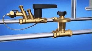
The range of balance cranes is constantly expanding due to the emergence of new high-tech products. An example is an Italian-made Caleffi vertical valve equipped with a flow meter.
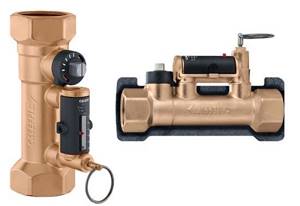
The Caleffi valve with flow meter can be mounted in 2 positions - horizontal and vertical
Types of valves and their design features
All new heating systems using radiator thermostats are considered dynamic. During operation, the thermostat installed on the heating device responds to any slight changes in the temperature conditions inside the room, thus changing the flow of heating water.
This creates a changing or dynamic operating mode in the heating system. It is a prerequisite for the introduction of automatic/dynamic balancing devices.
Classification of balancing valves by parameters:
- Type of coolant working medium: water, steam-water mixture, glycol composition;
- standard coolant parameters for volume flow, T and pressure;
- location points on the heating network: supply, return or bypass;
- purpose and number of floors of the heating facility; residential/public, single-story/multi-story;
- working function: automatic/mechanical.
- Their combination according to connection options is also practiced: threaded or flanged.
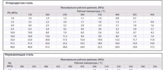
A variety of materials can be used to release valves. Static valves are most often made of brass, with a flanged/threaded connection, or cast iron, exclusively with a flanged connection. For dynamic modifications, in addition to brass/cast iron, they also use carbon steel, which is capable of providing the highest quality standard thermal and hydraulic characteristics of the system.
Manual balancers are required in order to adapt the heating network after installation, and automatic balancers change the characteristics of the heating network during the heating period.
When choosing a balancer modification, it is necessary to take into account various parameters:
- Type of heating circuit with natural/forced circulation.
- Thermal and hydraulic parameters of the network.
- installation point in the in-house system.
- adjustment parameters.
Mechanical balancer
Mechanical balancer
The mechanical valve has manual adjustment and works perfectly in a stable heating network. Works well for residential properties with not a very large number of heating devices. It facilitates repair and adjustment work, since when repairing a separate heating section there is no need to turn off the entire system.
Such modifications are very often equipped with measuring nipples capable of measuring the pressure in the system in the area where the valve is located. The main advantage of such regulators is their low price.
Mechanical balancer - the device works effectively in those facilities where the number of radiators is no more than 5 units. With more, the mechanics cannot cope and causes an imbalance in the heat supply circuit. When the thermostat on the 1st battery is closed, the coolant flow on the second increases. Due to this, the temperature of the water in some heating devices may rise to the boiling point, while in others it will remain cold. Only automatic balancers can solve this problem.
Automatic balancer
Automatic balancer
Installation of automatic units is carried out on branches/risers with a significant number of batteries. They differ from mechanical devices in the order of their operation. The balancer is adjusted to the position of the greatest throughput. When the hot water flow rate decreases by the thermostat on one of the batteries, the pressure increases. Then the impulse tube mechanism is activated, which analyzes the magnitude of the pressure drop. This approach allows for fine-tuning of the network.
The main advantages of automatic equalizers:
- The presence of a capillary tube that facilitates instant adjustment;
- the control unit does not change the pressure during operation, thereby preventing hydraulic vibrations in the network from disrupting the set mode;
- if necessary, special temperature independent zones can be installed in the general network;
- the high speed of adjustment of the balancer does not allow thermostats to rearrange their operation, which guarantees balanced operation of the entire intra-house heating system.
Peculiarities
Modern heating systems are characterized by uneven heat distribution across individual rooms. The amount of heat depends on the coolant flow, and the water flow is controlled by the balancing valve. If you do not use this device, the amount of heat received will decrease, moving away from its source. Accordingly, there will be different temperatures at different points in the network.
Previously, in simpler systems, this problem was solved by installing pipes with certain diameters or installing special throttle washers. The latter are characterized by a certain passage size, which ensures the flow of the required volume of water.
The design is a specific valve with which the flow of coolant is regulated. Sometimes, as an addition to this mechanism, two fittings are built in, which measure the pressure in different zones in relation to the control mechanism. Additionally, it connects to a capillary tube to coordinate with other controls.
There are two types of these valves: manual and automatic.
The first type, as you might guess from the name, is controlled manually. The products are inexpensive and therefore are the most common. By changing the pressure difference and water flow, they are able to adjust both individual sections and the entire system. In addition, at control points it will be possible to monitor the indicators of the working environment, and in the event of a breakdown, turn off any fragment and arrange repair work. Unfortunately, the adjustment of such valves is carried out under the condition of a constant flow of coolant. If it changes, the system will not be able to function. Therefore, it is better to install such models in private homes and with a simplified heating system.
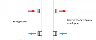
Automatic devices are attached to both the inlet and return pipelines. They are connected to each other by a thin tube, thanks to which the valve moves and shuts off the flow of water depending on pressure surges. Such a device is configured once and does not require further adjustment.
Valve models may differ depending on the coolant (steam, water or glycol solution), type of building (private house or ordinary high-rise building), installation location (on the supply or return pipeline), operating environment (at what pressure, temperature and volume of distilled water it operates device). Finally, valves can exhibit other properties, for example, regulate pressure and be equipped with additional devices, such as a measuring diaphragm.
Installation. Where is it installed?
Installation is carried out in the return branch circuit, which ensures a permanent supply of liquid to the batteries when operating one circuit for hot water supply and space heating. When installing balancing valves on each battery, installation is carried out in the lower part on the outlet pipe diagonally from the spherical coolant supply valve, which is mounted on top.
In a private cottage, differential pressure regulators are used for each battery, and for each outlet pipe they are provided with union nuts or another type of threaded connection. Automated installations do not require configuration. When using a two-valve design, the passage of the thermal energy source to the batteries furthest from the boiler is automatically increased.
Balancing is achieved by increasing the pressure on the circuits leading to the batteries closest to the boiler. The need to accurately calculate the indicators that are set on the valve is due to the features of the model. Manual valves typically require adjustment using calculations or measuring equipment.
In high-rise multi-storey buildings, valves are mounted on each common vertical pipeline (in the return line). When carrying out calculations, the given quantities of heat energy source supplied by an electric pump and the number of risers are used.
Purpose of the device
All branches of the heating system must receive the calculated amount of coolant. Previously, simple systems were controlled by using pipes of different diameters. In complex ones, special washers were installed, by moving which it was possible to change the cross-section of the pipeline. Today, a special valve is used that operates on the principle of a valve.
The balancing valve is equipped with two fittings, thanks to which
:
- the pressure of the coolant flow is measured before and after passing through the valve;
- a capillary tube is connected to allow adjustment.
Based on the readings of the device, it is possible to determine the pressure drop when water passes through the regulator, and calculate, according to the instructions, how many turns of the handle are required to optimize the operation of the heating system.
Note! A number of manufacturers offer balancing valves with a digital display, but such devices are more expensive.
Setting operating values
Experts offer two main options for setting up the balancing valve:
- using the handle adjustment scale;
- when connecting a differential pressure gauge to the valve.
The first option requires an accurate calculation of the setting value, which is calculated based on the following data:
- difference between upper and lower pressure;
- nominal diameter of the conductive hole (DN);
- flow in the riser.
To set the design flow rate, you need to use the handle to set the desired value, which, as a rule, consists of a whole number and tenths. First the whole part is set, then the tenths. The handle rotates clockwise from the fully open position. To fix the set value, depending on the model, either a hexagon is used, or the value is set by pressing the handwheel.
Balancing valve for heating system
Existing heat supply systems are conventionally divided into two types:
- Dynamic. They have conditionally constant or variable hydraulic characteristics, these include heating lines with two-way control valves. These systems are equipped with automatic balancing differential regulators.
- Static. They have constant hydraulic parameters, include lines with or without three-way adjustment valves, the system is equipped with static manual balancing valves.
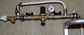
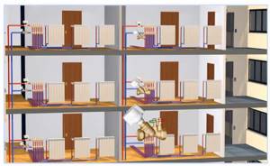
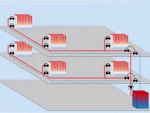
Rice. 7 Balancing valve in the line - installation diagram of automatic fittings
In a private house
In a private house, a balance valve is installed on each radiator; the outlet pipes of each of them must have union nuts or another type of threaded connection. The use of automatic systems does not require adjustment - when using a two-valve design, the supply of coolant to radiators installed at a large distance from the boiler is automatically increased.
This occurs due to the transfer of water to the actuators through a pulse tube under lower pressure than that of the first batteries from the boiler. The use of another type of combined valves also does not require calculating heat transfer using special tables and measurements; the devices have built-in control elements, the movement of which occurs using an electric drive.
If a manual balancer is used, it must be adjusted using measuring equipment.
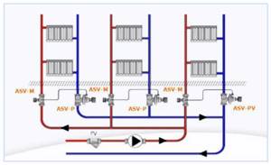
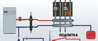
Rice. 8 Automatic balancing valve in the heating system - connection diagram
To determine the volume of water supplied to each radiator and, accordingly, balancing, an electronic contact thermometer is used, with which the temperature of all heating radiators is measured. The average supply volume per heater is determined by dividing the total value by the number of heating elements. The greatest flow of hot water should flow to the furthest radiator, a smaller amount to the element closest to the boiler. When carrying out adjustment work using a manual mechanical device, proceed as follows:
- Open all control valves all the way and turn on the water, the maximum surface temperature of the radiators is 70 - 80 degrees.
- Using a contact thermometer, measure the temperature of all batteries and record the readings.
- Since the furthest elements must be supplied with the maximum amount of coolant, they are not subject to further regulation. Each valve has a different number of revolutions and its own individual settings, so the easiest way is to calculate the required number of revolutions using the simplest school rules based on the linear dependence of the radiator temperature on the volume of passing coolant.
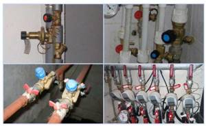
Rice. 9 Balancing fittings - installation examples
- For example, if the operating temperature of the first radiator from the boiler is +80 C., and the last +70 C. with the same supply volumes of 0.5 m3/h, on the first heater this indicator is reduced by a ratio of 80 to 70, consumption will go less, and the resulting volume will be 0.435 m3/h. If all the valves are not set to the maximum flow, but set to the average value, then you can take the heaters located in the middle of the line as a guide and similarly reduce the throughput closer to the boiler and increase it at the farthest points.
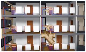
In a multi-storey building or building
The installation of valves in a multi-storey building is carried out in the return line of each riser; if the electric pump is far away, the pressure in each of them should be approximately the same - in this case, the flow rate for each riser is considered equal.
To set up in an apartment building with a large number of risers, it uses data on the volume of water supplied by an electric pump, which is divided by the number of risers. The resulting value in cubic meters per hour (for the Danfoss LENO MSV-B valve) is set on the digital scale of the device by rotating the handle.
How to balance a radiator network
Typically, installers of heating systems set the coolant flow rate on the batteries in a simple way: they divide the number of revolutions of the balancing valve by the number of heating devices and in this way calculate the adjustment step. Moving from the last radiator to the first, close the taps with the resulting difference in speed.
Example. On one “arm” of the dead-end system we have 5 radiators with Oventrop manual valves with 4.5 spindle turns. Divide 4.5 by 5, we get an adjustment step of about 0.9 turns. This means that we open the penultimate heating device by 3.6 turns, the third by 2.7, the second by 1.8, and the first by 0.9 turns.
The method is quite approximate and does not take into account the different power of batteries, and therefore can be used as a preliminary setting with adjustments during operation.

A contact thermometer that measures the surface temperature of pipes and radiators will help you balance your heating more accurately.
Our experienced expert Vladimir Sukhorukov offers another technique based on measuring the actual surface temperature of heaters. The step-by-step balancing instructions look like this:
- Open all balancing valves as much as possible and put the system into operating mode with a supply temperature of 80 °C.
- Use a contact thermometer to measure the temperature of all heating devices.
- Eliminate the resulting difference by tightening the taps of the first and middle radiators; do not touch the end ones. Open the near battery by 1-1.5 turns of the valve, the middle ones by 2-2.5.
- Allow the system to adapt to the new settings for 20 minutes and repeat the measurements. Your task is to achieve a minimum temperature difference between the battery farthest and closest to the boiler.
Note. The weather and outside temperature do not matter, only the difference in the heating of the radiators is important. By the way, in normal operating mode at 50-70 °C at the supply temperature delta will become even lower. How the system is hydraulically balanced using balancing valves, watch the video from an expert:
Valve installation
When installing the valve, it is necessary to place it in the direction of the arrow on the body, which indicates the direction of fluid movement, to combat turbulence, which affects the accuracy of the settings. Select straight sections of pipeline with a length of 5 diameters of the device and its location points and two diameters after the valve. The equipment is installed in the return branch of the system; a plumbing adjustable wrench is sufficient to carry out the work; installation is carried out in the following sequence:
- Before installation, be sure to flush and clean the pipeline system to get rid of possible metal shavings and other foreign objects.
- Many devices have a removable head; for ease of installation in pipes, it should be removed in accordance with the instructions.
- For installation, you can use flax fiber with appropriate lubricant, which is wound around the end of the pipe and the battery outlet fitting.
- The control valve is screwed onto the pipe at one end, the other is attached to the radiator with special washers (American adapter coupling), which is placed on the outlet radiator fitting or screwed into the valve, playing the role of a connecting coupling.
Rice. 10 Installation of balancing valves
Installation
The balancing valve, designed to control the heating system, is very easy to install with your own hands. Installation is carried out as if installing a regular ball valve. In principle, it is not particularly important how the valve itself will be placed in space, but the arrow on the body must correspond to the direction of water flow. Otherwise, the valve will begin to create resistance to the coolant. The temperature and pressure of different valves may vary, therefore, after studying the characteristics of your own heating system, it is better to find the most suitable option from the manufacturers.
It is necessary to place special protection in the form of a filter in front of the valve. This device will prevent debris and dirt from getting onto individual elements of the regulator. In addition, it is recommended to install the valve so that there are significant gaps of straight pipe before and after it. This will prevent the appearance of bends that affect the movement of water. Also, before starting installation, the pipes must be flushed.
Installation of the valve begins after checking the condition of the pipes is completed - it is necessary to check their integrity and the absence of debris. Then the location where the device will be placed is determined. The parameters of the straight pipe sections before and after the valve must correspond to the following figures: five diameters before the element and two diameters after the element or even more, this will eliminate turbulence.
Then the valve is screwed into the thread of the pipe, previously equipped with tow.
Threading on the pipe can be done with a die or other similar tool. For a quality connection to the valve to occur, the thread length must be up to seven turns.
Setting the balance valves
To balance the heating in a private house, select manual devices of the required diameter, selecting and configuring them using the appropriate diagram included in the passport. The initial data for working with the graph are the supply volume, expressed in cubic meters per hour or liters per second, and the pressure drop, measured in bars, atmospheres or Pascals.
For example, when determining the position of the adjustment indicator of the MSV-F2 modification with a nominal bore DN equal to 65 mm. at a flow rate of 16 cubic meters per hour. and pressure drops of 5 kPa. (Fig. 11) on the graph, connect the points on the corresponding flow and pressure scales and extend the line until the conventional scale intersects the coefficient Ku.
From the point on the Ku scale, draw a horizontal line for diameter D equal to 65 mm, find the setting with the number 7, which is set on the handle scale.
Also, for the selected diameter of the device, its adjustment is carried out using the table (Fig. 12), from which the number of spindle revolutions corresponding to a certain flow is determined.
Rice. 11 Determination of the position of the valve scale at a known pressure and a certain water supply
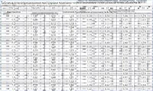
Rice. 12 Example table for manual configuration
Operating principle of the balancing valve
To understand how this device works, let’s briefly examine the principle of balancing heating systems. Imagine a dead-end branch of a system with several radiators - consumers of thermal energy. Through the pipe, such a quantity of coolant heated to the design temperature should be supplied to them so that it is enough for all heated rooms. We know this expense from the calculation.
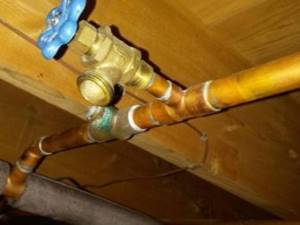
When the batteries are not equipped with thermostatic valves and the coolant flow for each of them is constant, a manual balancing valve is used for hydraulic adjustment. It is installed on the return pipeline at the point where it is inserted into the common pipeline. How this is done correctly is shown in the diagram:
Why use it
Installing balancing valves in the heating system, in addition to maintaining the same temperature of the radiators, in an individual home brings the following effect:
- Precise adjustment of the coolant temperature allows you to set its value depending on the purpose of the premises - in living rooms it can be higher, in utility rooms, storerooms, workshops, gyms, and food storage areas, you can set it lower using balancers. This factor increases the comfort of living in the house.
- Changing the coolant flow using a balance valve regulator depending on the purpose of the premises brings a significant economic effect, allowing you to save on fuel.
- In winter, when the owners are absent, constant heating of the home is necessary - with the help of balancing valves, you can adjust the heating system with minimal fuel consumption and maintain a constant temperature in all rooms. This advantage also saves financial resources for the owners.
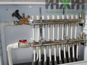
Rice. 3 Manual balancing valves for heating and hot water supply (DHW) systems in the house
How else is a balancing valve used?
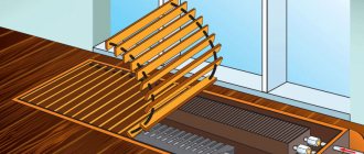
In addition to regulating individual branches and risers in the heating system, the device is also used for other purposes. For example, a balance valve is installed in the small circulation circuit of a solid fuel boiler when it is closed to a buffer tank. The point is to maintain the water temperature in the circuit at least 60 ºС and not install a mixing unit for this. But in this case, the flow rate in the boiler circuit should be higher than in the heating circuit. This is what the valve installed on the supply does.
Another installation option is that a balancing valve regulates the supply of coolant to the indirect heating boiler coil. The latter, as a rule, is connected directly from the boiler unit, so it would be correct to limit the amount of coolant for heating the boiler. It must be said that ideally it is better to equip all branches of the system with balance valves, including underfloor heating and hot water circuits. Such measures improve the quality of heating operation and definitely lead to energy savings.
Purpose and functions
Many people are directly interested in what this tap or valve is actually needed for. What functions does it perform?
This question can only be answered by first considering the conditions in heating systems.
A standard heating system constantly drives media through its pipes from one unit to another. The main heating is carried out by supplying media to radiators or other similar systems. The radiator, if there is a sufficient amount of liquid inside and normal temperature, transfers heat to the room with great efficiency.
However, this is how the pipeline system operates under conditions close to ideal. Unfortunately, ideal conditions are often unattainable or partially achievable.
In a pipeline with constantly heated water, the pressure level and temperature of the medium may change. This leads to uneven distribution of flow through the pipes. Which, of course, I would like to avoid.
Some pipes end up receiving more heat, others less . For a heating system, this scenario is the worst. This is what a balancing valve or tap is used for.
Balancing valve for heating system
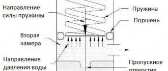
Its task is to automatically control the level of pressure and heating of the media, as well as adjust its supply in case of changes in the parameters described above.
The faucet is easy to set up and operates with a simple spring and a few additional elements. At the same time, the balancing valve performs truly titanic work, cutting off individual branches of the system into logical parts and monitoring the state in them.
On large pipelines, one tap will not solve the problem; you will have to install more of them. But believe me, it's worth it.
There are a lot of such products on the market from different manufacturers. The most popular brands are Stremax, Cimberio, Stad and others. They are the ones who have reliably held their position in the market for many years.
General operating principle and design
A standard balancing valve is very similar to a pipeline valve, but there are a few differences.
This is also a fitting, but a fitting designed not to completely shut off the system (although some models Shtremax, Cimberio, Stad can do such things as part of the standard balancing load) but to regulate it.
Valve design
The basis of balancing valves is a special spring, which is adjusted by rotating two knobs. Handles affect its rigidity. The stiffer the spring, the more pressure it can withstand.
The interaction of the spring with the level of nominal pressure makes it possible to easily control the flow force in the pipe, while taking into account its additional characteristics.
All mechanisms are sealed with rubber gaskets. Near the spring there is a cartridge that simplifies the operation of the valve. The flow is closed due to the movement of the spool towards the fitting seats. The spool is most often also controlled by the action of a spring.
In advanced models such as Stremax, Cimberio and Stad, you can set boundary conditions for the valve under which it will completely close or open the flow.
Using Flow Meters
Sometimes the valves are equipped with a flow meter. Using a flow meter gives us several advantages, including the ability to:
- follow the flow;
- fine tuning;
- automation of the regulation process.
At the same time valves with a flow meter are quite expensive and can cost you at least several times more than conventional ones.
As a rule, if a device is equipped with a flow meter, then it belongs to the highest class of fittings, therefore, automation will also be installed on it.
There are also advanced valves that operate entirely using electronic parts, capable of independently assessing the situation, equipped with sensors and controlled from a single center. In civil engineering, such solutions are almost never used due to their high cost.
Types and differences
Ballorex balancing valves and taps can be considered quite stable equipment, in terms of the availability of many varieties.
To a greater extent they repeat each other's design. The main division occurs due to several details.
First of all, they are divided according to the type of drive or control into:
- Manual.
- Automatic.
The former require manual configuration and control, the latter are complete automatic machines, mainly capable of organizing into a single system. The price difference between them is very significant.
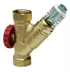
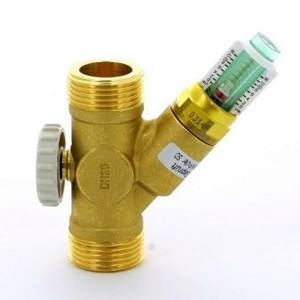
Fitting with adjustment and flow meter
Equally important is the presence of additional details. Cranes are often equipped with :
- flow meter;
- sensors;
- automation;
- protection;
- pressure gauges.
There are plenty of variations. You just need to understand that you don’t have to buy the most expensive and sophisticated option. It is quite possible that you will not need the same pressure gauge or flow meter at all. And it costs a fair amount of money.
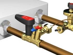
Where and when is the main valve installed?
Most private homes use manual radiator valves. They are quite enough for normal adjustment of water heating in cottages whose area does not exceed more than 500 m². Installation Installation of main-type balancing valves in the heating system is done in the following cases:
- in buildings where an extensive heating network with a large number of risers is installed;
- in apartment buildings that are heated by their own boiler room;
- when connecting a solid fuel boiler with a heat accumulator.
Once you have an idea of the purposes of balancing valves, you need to understand the specific locations of their installation. Radiator valves must be installed at the outlet of the heater, that is, on the return line, and main valves must be installed on the pipeline that brings cooled water from consumers to the boiler room. In the case when the element is paired with an automatic pressure regulator, it can be installed both in the return and supply pipelines, depending on how the circuit itself is designed.
Note: aluminum and steel radiators with bottom connections are already equipped with a balancing valve, which is built into the special fittings that are necessary to connect the connections to such devices.
We list the points in which it is not necessary to install control valves:
- in short-term dead-end systems, which have identical hydraulic “shoulders”;
- in the case when the batteries are equipped with thermostatic valves with presetting;
- in collector-type heating systems.
- on the last (dead-end) heating radiator;
Temperature regulators with presetting, which are installed on the water supply to the battery, also act as a balance valve, therefore it is necessary to install a shut-off ball valve at the outlet of the heating device. Such fittings are installed on the connections to the last radiator in the chain, since there is no particular point in adjusting it, and it must be completely open.
Principle of operation
Balancing will have to be done in the following cases:
- Initially, mistakes were made at the design or installation stage of the heating system;
- there was a radical replacement of batteries with those that do not correspond to the design;
- the pipeline design has changed;
- the system, due to lack of timely cleaning, became clogged.
Even one of the above situations can lead to problems with heating: oxygen-hydrogen plugs, temperature deviations and excessive consumption of energy required for heating will occur. As a result, apartment residents will become very uncomfortable in the premises.
You should begin installing the valve only after understanding the purpose of the device, as well as how it works. In short, the handle rotates - the section size changes due to the fact that the spool has blocked the flow. The cross-section has decreased - the hydraulic resistance has increased - the flows in different pipes have been leveled out.
Advantages of fittings
Manual balancing valves have many advantages. They are cheaper than automatic models. In addition, they are distinguished by the following features.
- Increased reliability.
The device operates stably even under conditions of increased loads and significant pressure fluctuations. - Maintainability.
This type of fittings has a simple design, which very rarely fails and can be easily repaired if necessary. - Easy setup.
Using the screw handle, you can set the required operating parameters in just a couple of minutes. - Balancing accuracy.
Several positions, clearly indicated on a special scale, allow you to fine-tune the operation of the system. - Functionality.
The valves are excellent for operating in systems with different operating environments and settings. - Blocking the flow.
If necessary, the device can serve as a shut-off valve. In this case, you can stop the flow without changing the settings made. - Easy installation.
The valve is quickly installed on the pipeline using flanges or internal threads, creating a strong and tight connection. - Removable handle.
When operating the valve in cramped conditions, the handle can be removed and the device can be controlled using a hex key. - Internal drainage.
The device has built-in pipes that can be used for quick two-way drainage of the system.
Main characteristics and features of the balancer
The Pulsar Compact valve is compact in size, which allows it to be installed in confined spaces. On the front side there is a clear, easy to read preset scale. The kit includes a setting key. In addition, the balancing valve consists of the following elements:
- locking handle;
- pointer;
- stock;
- frame;
- connecting pipes with internal thread.
The connecting element for the locking handle or servo drive can be supplied separately.
The balancing valve is available in different sizes for different pipe diameters.
Recommended Manufacturers
Several global manufacturers are engaged in the production of such shut-off and control valves. The operation of the heat supply depends on the quality of materials, accuracy of settings and design. Therefore, it is recommended to buy original models rather than analogues. This will increase the reliability of the system.
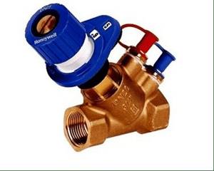
You can find balancers on the market from Valtec, Danfoss, Herz and Honeywell. They differ only in appearance, their functional features are the same. The table shows popular heating balancers from these manufacturers.
| Manufacturer | Mechanical balancer | Automatic balancer |
| Valtec | VT.042.G | VT.040.G |
| Danfoss | Leno MVT or MNT | AB-PM, APT or ASV |
| Herz | 4017 M | TS-V |
| Honeywell | Kombi-3-Plus | — |
These models differ in size and connection methods to the pipeline. Some of them are designed only for cold water supply, but most are universal and can be used for heating and water supply. An example is Danfoss products.