Home / Boiler rooms
Back
Published: 05/14/2019
Reading time: 2 min
0
7672
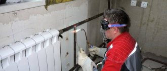
Boiler lining is a complex and high-tech process that includes installation of a system of fireproof and heat-insulating boiler enclosures designed to protect the room from gas waste and insulate the combustion chamber. This design is a combined system of brick, insulating materials, mortar, metal frame and sheathing.
Not afraid of high temperatures and changes, the influence of combustion products and gases. To increase efficiency and prevent heat loss, the design must be technically robust, not complicated in design and not interfere with the installation of the boiler.
- 1 What is boiler lining
- 2 Purpose of lining
- 3 Types and features of lining
- 4 Technology of lining boiler equipment
Introduction
This instruction is a guide to the production of brickwork during the installation of hot water boilers and is intended for the installation of hot water boilers and is intended for installation personnel directly involved in the execution of brickwork. The instructions provide methods for making linings from refractory concrete, ramming masses, coatings, etc.
When carrying out lining on hot water boilers, it is also necessary to follow the “instructions for the production of lining work during the installation of boiler houses and energy technology installations” volume 1; 2 issued by Soyuztechenergo in 1988 (hereinafter referred to as the “Soyuztechenergo” instructions). This instruction provides a more detailed detailed description of all types of lining work, requirements for quality control, as well as types and brands of lining materials, recommendations for use.
1. Brief description of the lining design and thermal insulation.
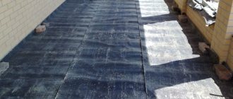
- The lining of hot water boilers is tube-based, lightweight. It consists of a layer of fire-resistant chamotte concrete, which is applied over a metal mesh of a heat-insulating layer and a sealing coating (plaster), also applied over the mesh and covered with fabric on the outside. On some types of boilers, instead of chamotte concrete, a 2 mm thick steel sheet casing is used. The total thickness of the lining is ~ 112 mm. The weight of one square meter of lining made on screen pipes is no more than 100 kg.
- Burner embrasures are formed from fireclay concrete, fireclay bricks, chromite mass, steel parts or other materials in accordance with the requirements of the drawing.
- Unheated parts of the collectors and curved surfaces of the screens are insulated with asbestos-diatom concrete.
- Ash bunker, gas boxes, pipelines, air heaters, etc. are insulated with heat-insulating mats or other heat-insulating materials padded under the mesh.
- On top of the thermal insulation of the elements, a layer of asbestos-cement plaster is applied over the mesh, followed by covering with fabric.
Lightweight lining
| Lightweight lining and its fastening.| Brick vault. |
Lightweight lining is used in boiler units with medium and high steam output. It is made in the form of two or three layers with a total thickness of no more than 300 - 500 mm. Its inner layer is lining, the middle layer is insulating, and the outer layer is brickwork. To protect the lining from mechanical damage and create the necessary seal, it is additionally sheathed on the outside with metal sheets 3-4 mm thick. Such lining is attached to the frame every 1 5 - 2 m in height.
| Exchange structures |
Lightweight lining does not have connections between the refractory and insulating layers, so individual parts of the lining can move freely relative to each other.
Lightweight lining of medium-capacity boilers is structurally carried out according to two main schemes - in the form of a monolithic scaffold lining and lining with weight transferred to the boiler frame using special unloading brackets. Pipe lining, in which heating surfaces are used as supporting elements, is not widely used in medium-pressure boilers.
The lightweight lining of the stud is attached to the pipes, the frame is made in the form of a pedestal. The boiler, starting from the 5-4 m mark, expands upward.
Lightweight lining usually consists of two or three layers. A layer of fireclay or red brick faces the inside of the flue. Fireclay bricks should be installed where the temperature of the inner surface of the lining exceeds 600 - 700 C, as well as in areas where slagging is possible. Behind screen pipes with thick screening and refractory ash, as well as along the walls of a water economizer, it is permissible to install high-quality red brick laid on a mortar of refractory clay and ground fireclay.
Lightweight lining attached to the boiler frame made of piece refractory and heat-insulating products. This lining design has a steel sheet casing.
| Layout of heavy lining and temperature at layer boundaries. |
Lightweight lining is used to reduce the temperature of the fire surface of the inner layer to 450 - 800 C due to shielding the walls of the combustion chamber.
Lightweight lining does not have the same stability and strength as heavy lining made in the form of walls. Therefore, sections of lightweight lining are attached to the beams and panels of the frame. To increase the density (impermeability) of the lining and its strength, the outer layer of insulation is covered with steel sheets (cladding) 2 - 3 mm thick. These sheets are welded to the frame.
Lightweight lining does not have the same stability and strength as heavy lining made in the form of walls, so sections of it are attached to the beams and panels of the frame. To increase the density (impermeability) of the lining and its strength, the outer layer of insulation is covered with steel sheets (cladding) 2-3 mm thick, which are welded to the frame.
Lightweight lining for newly developed powerful boilers, as a rule, is not used. However, its use is advisable for those boilers in which, due to the characteristics of the fuel burned, the lining is in difficult conditions and requires more frequent repairs.
| Monolithic lightweight pipe lining.| Prefabricated pipe lining of the DKVR boiler. |
Based on the method of transmitting mechanical loads, lightweight linings are divided into on-tube linings, which transfer loads to the boiler screen systems and through them to the boiler frame, and on-frame linings, which transfer loads directly to the boiler frame.
Reinforcement works
- The types and grades of steel used for concrete reinforcement, as well as the wire diameters and types of mesh must strictly correspond to the design ones.
- The lining fastening parts, reinforcement and mesh must be thoroughly cleaned of dirt, loose rust, adhering mortar, etc.
- When making reinforcement from individual intersection rods, it is advisable to weld them using resistance or arc welding. Manual tying of reinforcement should be done with annealed steel wire with a diameter of 1.6-2.0 mm. Tying reinforcement with aluminum wire is strictly prohibited.
- The reinforcement must be securely fastened to avoid displacement when laying concrete.
- The minimum installation distance of reinforcement from the concrete fire surface must be at least 25 mm
- Tensioning the mesh for reinforcing refractory concrete when lining the screens must be done without sagging or slackening. To do this, first the mesh is stretched parallel to the plane of the screen at the ends of the pins securing the lining, and then settles.
- The mesh in the places adjacent to the stiffening belts of the screen blocks must be carefully secured using hooks or rods (made of wire with a diameter of 5-6 mm), passed into the edge of the mesh and welded to the spacer combs. The welding pitch of hooks or rods should not exceed 150 mm. The mesh should be tied to the outer blocks with wire with a diameter of 1.6-2.0 mm, the tie step should be no more than 100 mm.
- The mesh for reinforcing sealing plaster should be attached similarly to the mesh for reinforcing refractory concrete. The mesh is stretched over the surface of the insulation, made of heat-insulating concrete, and must be fastened with wire staples driven into the concrete, and in places where the mats adjoin the mesh - with annealed steel wire with a pitch of 30-50 mm.
How to protect boilers with lining
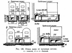
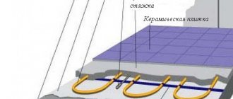
Scheme of smoke removal from cast iron boilers.
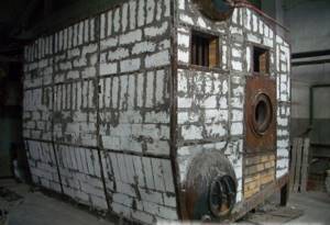
Lining is used only for those boilers that do not have all-welded screens. Such a shell is necessary to ensure that all combustion products exit the boiler correctly, and it also provides additional insulation. The simplest boiler lining can be seen in laundries, where brick walls are laid out for this purpose. It should be clarified that lining can be very complex, so it is best done only by specialists. Additional insulation is required only for steel boilers; for cast iron there is no particular need for this.
Types of boiler lining:
- Heavy (brick). It is used for boilers with low power, the height of the walls does not exceed 12 m.
- Lightweight (fire-resistant material is used).
- Lightweight (concrete). Has a small mass.
Carrying out brickwork works.
- The lining of the boiler elements is carried out before they are installed in the operating position. This should especially be taken into account when installing PTVM-30M boilers, since the distance between the rear wall and the convective part blocks is very small, which creates a number of inconveniences during bricklaying work. It is allowed to carry out brickwork work after installation of heating surfaces. On boilers equipped with RGMG-10,20,30 burners, as well as PGMG-30, 40 burners, the screens on which the embrasures are located must be lined before installing air ducts on them. In this case, special attention should be paid to the formation of the embrasure profile.
- Pins are inserted and welded into the holes of the strips welded to the screen pipes.
- Kraft paper coated with liquid glass is pinned onto the pins of the screens. Then steel mesh No. 20-2.0 is stretched in accordance with clauses 3.6; 3.7. It is possible to carry out lining without the use of kraft paper.
- In places where manholes, peepholes, etc. are installed, reinforcement made of wire with a diameter of 5 mm, with a cell size of no more than 100x100 mm, is welded to the pipes.
- Between the risers of the convection shaft, strips of plywood or other material are fastened with wire so that the gaps are completely closed. In areas covered by fins, stripes are not installed.
- The movable fastenings of the convective block coils are tightly insulated with asbestos cord or other heat-insulating material.
- A mesh No. 45-3.0 is stretched over the surface of the risers of the convective block. The use of mesh No. 20-2.0 is allowed.
- Before laying the concrete mixture, the correct installation and reliability of the mesh and reinforcement must be checked.
- Chamotte concrete is laid on the heating surface from Ø60 pipes with a thickness of 20 mm. On the surface of the Ø83 risers of the convective shaft, concrete is laid with a thickness of 30 mm.
- When lining individual blocks before their installation, concrete is not placed along the edges of the blocks (along their length). The width of the unconcreted edges of the mesh should be about 50 mm.
- It is recommended to prepare heat-resistant chamotte concrete in a forced-action concrete mixer, into the drum of which all dry materials are loaded and mixed thoroughly for 1 minute. The dosage of cement is carried out with an accuracy of ± 1% by weight, and of aggregates with an accuracy of ± 2%. After this, add the mixer (water) and mix the concrete mixture until completely homogeneous, but not less than 5 minutes. At an ambient temperature of +25ºС and above, the mixing water should be cold. The time from the moment of preparing the concrete mixture to the moment of its laying should not exceed 45 minutes. Preparation and laying of refractory concrete using alumina cement should be carried out at a temperature not lower than 7ºС.
- Control during the preparation of concrete mixture consists of:
- a) in checking the compliance of the materials used with the requirements of state standards and technical specifications.
- b) in monitoring the correctness and accuracy of the dosage of concrete components in accordance with the established composition.
- c) in checking the fineness of grinding and granulometric composition of aggregates
- d) checking the duration of mixing the concrete mixture
- e) checking the mobility of the concrete mixture at least once a month
- c) checking the thoroughness of cleaning the mixer during long (more than 1 hour) stops.
- Transportation of concrete mixtures to the place of installation should be carried out with the least number of overloads under conditions that prevent the mixture from separating. During transportation, loss of cement laitance and penetration of atmospheric precipitation into the concrete mixture is not allowed.
- Control over the transportation of concrete mixture consists of:
- a) taking into account the time from the start of preparing the concrete mixture until it is delivered to the place where the concrete is laid, which should not exceed the setting time of the cement (45 minutes for aluminous cement)
- b) in checking the cleanliness of the container and monitoring the taking of measures against laitance, as well as precipitation entering the concrete; c) in checking the absence of delamination of the concrete mixture.
- Laying the concrete mixture, including in the area of the burner embrasures, should be carried out in an even layer. Concreting must be carried out continuously (the interval between the completion of compaction of one and the supply of the next portion of concrete should not exceed 1 hour). Compaction of fireclay concrete is carried out using surface and internal vibrators or on vibrating platforms. In places inaccessible for compaction with vibrators, compaction of heat-resistant concrete by manual tamping is allowed.
- Control when laying concrete mixture consists of:
- a) in monitoring the thorough lubrication of the inner surface of the formwork, eliminating cracks and cleaning the formwork from dirt.
- b) in checking the frequency of the reinforcement, the presence of burn-out coating on the lining fastening parts, the correct location of the reinforcement and fastening parts and the reliability of their fastening.
- Drying concrete requires a certain temperature regime. The favorable air temperature for hardening conditions is from +15 to +25ºС, and the minimum air temperature at which concrete hardening is allowed should not be lower than 7ºС. If the air temperature exceeds +15ºС, then the surface of the laid concrete mixture should be covered with moistened matting, burlap, a layer of sawdust or sand. Concrete should be moistened during the day at the following intervals at maximum air temperature:
- 15-30ºС after 4 hours.
- 30-35ºС after 2 hours.
- 35-40ºС in 1.5 hours.
- over 40ºС after 1 hour.
- At night, the break between moisturizing can be increased, while the shelters should be kept wet at all times. For concrete based on alumina cement, heat and moisture treatment is not allowed.
- Quality control of refractory concrete is carried out by testing samples:
- a) the compressive strength of concrete is determined after drying it at a temperature of 100-110ºC, which must be at least 10 MPa (100 kgf/cm²).
- b) the residual tensile strength is determined after heating to 800ºC, which must be at least 7 MPa (70 kgf/cm²).
- c) the volumetric mass of concrete is determined, which must be at least 1800 m³/kg.
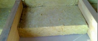
- Stitched mineral wool mats are installed on top of the chamotte concrete in accordance with GOST 211880-94
- It is allowed to replace mats with other heat-insulating materials with appropriate thermal properties. Before installing the mats, it is necessary to check the quality of the chamotte concrete layer and eliminate all defects (cracks, chipping of pieces, etc.).
- The installation of thermal insulation material is carried out after the concrete reaches 70% of its final strength.
- The outer surface of the strips of heat-insulating material is carefully leveled, and it is stitched together with wire. The voids between the strips are tightly filled with mineral wool or wool from another thermal insulation material. In places where the headset is installed, the thermal insulation is cut in place. The edges of the mesh are folded and stitched. Thermal insulation is fastened using Ø5 mm wire welded to the steel parts of the headset.
- The surfaces of the collectors facing the firebox are shotcrete with fireclay concrete, if required by the drawing.
- Wire reinforcement Ø5mm. in the form of staples 150-200 mm long. welded to the collectors in such a way that cells measuring 100x100 mm are formed. Rods made of Ø5mm wire are stretched over the brackets. in accordance with clause 3.3.
- Curvilinear surfaces of screens and unheated surfaces of collectors are insulated with asbestos-diatomaceous concrete and mesh No. 20-2.0 is stretched over its surface in accordance with clause 3.8. the edges of the mesh adjacent to the mats are sewn to the mesh securing the mats.
Preparation and application of sealing plaster.
- The surface of the heat-insulating layer of the lining is plastered with sealing magnesium coating. Replacement with asbestos-diatom plaster, ORGRES coating and asbestos-cement plaster is allowed.
- Fluffed asbestos used for preparing sealing plasters must be dry. If there are caked lumps and foreign inclusions, asbestos must be sifted.
- When preparing a solution of magnesium chloride from a crystalline product, the latter is dissolved in warm water to obtain a solution with a specific gravity of 1.2-1.25 g/cm².
- Plastic refractory clay must be dried, ground and sifted.
- Before applying sealing plasters, the mesh must be carefully tensioned and secured, and the mesh itself must be cleaned of debris, dirt, etc.
- The plaster is poured onto the mesh in small portions, and then carefully compacted and leveled. Magnesia plaster should be applied immediately to the entire thickness of the layer. It is advisable to apply asbestos-cement plaster in two or three layers, carefully punching it behind the mesh. When applying plaster, the same layer thickness must be maintained.
- If cracks appear in hardened plaster, its surface is rubbed over with a thin layer of plaster of the same composition.
- After drying the sealing plaster, its surface is pasted over (it is advisable to use calico with an adhesive composition of liquid glass and refractory clay) followed by coating with aluminum paint AL-177.
- Work on applying magnesium plaster is allowed to be carried out at an ambient temperature of not lower than +10ºС, and of asbestos-diatom plaster not lower than +5ºС.
- Wetting of sealing plasters by atmospheric precipitation during their hardening is not allowed.
- Sealing plasters are applied after the lining has completely dried.
Basic requirements for boiler lining
Tool for bricklaying works.
The insulating layer must be dense, without cracks. Sometimes special fire-resistant masonry is necessary. In this case, you can use fireclay bricks. It must be sorted, because there are places in the lining of boilers where the masonry must be especially strong; broken bricks cannot be used in them. The masonry seam must be airtight, and broken edges will not allow this to be achieved. The seams must be so perfect that even a whole brick is checked using a special template.
Close attention should be paid not only to the bricks, but also to the mortar. It must be cooked very well, stirred thoroughly
If the brick is fireclay, then the composition is prepared from a mixture of fireclay powder and refractory clay. The amount of powder will depend on how fatty the clay is. The higher the fat content of the clay, the more powder you will need. Sometimes stove makers add regular sand and table salt to refractory clay. This cannot be done when lining boilers.
Conventional masonry requires that the thickness of the mortar does not exceed 3 mm, complex masonry - even less. Therefore, the composition must be mixed very carefully, otherwise it will not be possible to achieve the desired result. If the masonry must be particularly careful, then only a liquid mixture is used. For just careful masonry, you can use a medium-thick solution, but for a regular one, the composition should be the consistency of sour cream.
You cannot use dirty water for cooking, as is usually done at many construction sites. The refractory mortar must not contain any impurities, such as lime residues. Therefore, it is kneaded only in a separate clean container. For low-heat areas, complex lime mortars can be used.
Stuffing the studded part of the burner embrasures with chromite mass.
- Burner embrasures are formed from fireclay concrete, fireclay brick, chromite mass or other materials in accordance with the requirements of the drawing.
- Before applying chromite mass, studded surfaces must be cleaned of metal, paint, scale, etc.
- After cleaning, the surface is blown with compressed air. Applying the mixture to a dusty surface is not allowed.
- Before applying the mass, the reliability of the reinforcement must be checked.
- When applying the mass manually, packing in several layers is not allowed.
- The density of the packing should be maximum, since the degree of compaction of the mass determines its durability. The presence of voids between the tenons and pipes, the possibility of pressing the stuffing with your fingers, should not be used.
- The outer surface of the compacted mass should not be smoothed.
- Work on applying the ramming mass must be carried out at an air temperature of at least +10ºС.
How to hide communications?
In addition to the gas boiler itself, it is necessary to hide all communications from view. The pipe through which gas is supplied to the boiler is prohibited from being walled up in the wall. It is desirable if the remaining pipes are within access for their maintenance. If communications are not covered, the look in the kitchen will be completely unaesthetic. To hide them externally, you can purchase special panels or a decorative box at a hardware store. It is not very difficult to make such a box yourself, then paint it to match the color of the interior or cover it with film to match the walls.
Advice. It is better if the decorative boxes are collapsible. Otherwise, they will have to be broken when the need arises to access any section of communications.
You will also need to hide the chimney pipe. To disguise it, you can make a decorative box with a heat-resistant inner surface or order a wall cabinet in the same style as the rest of the kitchen furniture. The material for making the cabinet must also be resistant to heat, since the pipe for removing combustion products heats up.
There are quite a large number of different options for how to hide a gas boiler in the kitchen. Therefore, when purchasing this useful equipment, there should not be any problems with how to hide it from view and not spoil the kitchen interior with the appearance of the unit.
Carrying out work on sealing joints of block linings.
- Before carrying out work on sealing the lining joints between the screen blocks, the correct installation of the latter must be checked.
- The edges of the mesh located in the clay concrete layer of adjacent screen blocks (width no more than 300 mm) must be sewn together with annealed wire with a diameter of 1.6-2.0 mm.
- Before concreting the lining joint, the previously laid concrete must be cleared and moistened.
- When concreting joints, for the convenience of applying chamotte concrete, it is allowed to add fireclay to its composition in an amount of up to 5%
- After installing mineral wool mats, mesh stitching must be carried out taking into account the requirements of clause 7.2
- The joints of the pipe lining of the front and side screen blocks in the area of the floor and ceiling must be carried out especially carefully.
- Concrete placed at the joints of the lining must be thoroughly compacted.
Solution
The mixture used for masonry is no less important. It should have a uniform structure without inclusions. A solution based on clay and fireclay powder is suitable for laying fireclay bricks. The degree of fat content of the clay determines the amount of powder. It is worth noting that salt and river sand cannot be added to the composition, despite the fact that such ingredients are often found in mortars for laying stoves.
The thickness of the mixture during complex lining should be within 2 mm; with conventional masonry, an increase of up to 3 mm is allowed. The result obtained directly depends on maintaining the proportions of the ingredients and thorough mixing. The consistency should be medium thick. The solution is mixed only with clean water, this guarantees the absence of lime and other impurities. It is recommended to prepare the composition in a separate, pre-cleaned container.
Thermal insulation of the external elements of the boiler.
- Thermal insulation of ash bins, gas boxes, air heaters, etc. made from heat-insulating mats with a total thickness of 80-100 mm. plastered with asbestos-cement plaster. It is allowed to pack thermal insulation material under the mesh.
- To attach thermal insulation to the insulated surface, pins 120-150 mm long are welded. Ø6mm. according to GOST 2590-88 with a pitch of 450 mm. After installing the thermal insulation and tensioning the mesh, the pins are bent.
- Descent, recirculation, bypass, steam removal pipelines and shot traps are insulated by packing thermal insulating wool under the mesh. Insulation with heat-insulating mats is allowed.
- After leveling the surface, asbestos-cement or other plaster with a thickness of 10-12 mm is applied to the heat-insulating layer.
- The finished plastered insulation must be even and smooth and firmly adhere to the insulated surface.
- Pasting and painting of the insulation is done after it has completely dried.
Order of conduct
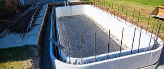
The lining work is carried out after the completion of hydraulic tests; in extreme cases, the foundation and the first row can be started simultaneously with the completion of the strength test. In general, it is enough to follow the requirements for lining, plan a detailed scheme in advance or take a ready-made one and follow it. Also, the main thing for the bricklayer is to follow these rules:
- The next row is placed only after the previous one is completely completed.
- Before laying each row, it is advisable to try on and fit all the bricks dry.
- Immediately cut off broken or damaged bricks during work.
- When taking a break from work, cut off the masonry with grooves (ledges) in different rows, and not vertically.
- Use exclusively a wooden or rubber hammer and compact each seam with it.
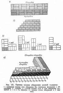
An example of masonry technique when working with brick.
Upon completion of the work, the lining must be dried: 10-12 days in natural mode with the combustion and smoke valves open, or 3-5 days in natural mode + several days at the minimum power of a continuously operating boiler.
Features of the production of lining works on certain types of boilers.
- On KV-GM-10,20,30-150 boilers, the lining of the front screen is heavy, the front wall is made of fireclay bricks. The thickness of the lining is 260 mm. The under is made of fireclay bricks in two rows. Fireclay bricks are laid on top of a foundation made of ordinary bricks. In this case, in accordance with the requirements of the drawing, the angle of inclination of the hearth and the gap between the screen pipes and the brick must be maintained. The interpipe space of the intermediate screen is filled with fireclay bricks. The front wall of KV-TS boilers is made of fireclay bricks. The embrasures of the throwers and pre-fireboxes are lined according to the drawings of the manufacturer of the TLZM and TCZM fireboxes.
- The design of the lining of gas-tight screens of boilers operating under pressurization differs in that chamotte concrete is not applied to the screen surfaces, but only thermal insulation is installed. Wire pins Ø6-8 mm are welded to the fins of the screens. GOST 2590-88 with a pitch of 350-450 mm.
- Mineral wool mats with a total thickness of 160 mm are pinned onto the pins. or a mesh is installed and sheathing is done with a metal sheet or coating on the mesh.
- In places where there are no fins between the pipes, pipe panels and risers are sheathed with a metal sheet 1.5-2.0 mm thick. to ensure gas tightness, then, in accordance with the requirements of the drawing, pins are welded at the junction of the sheet to the pipes or directly to the pipes.
Boilers “DKVR”
Systems of this series are designed to provide heated water and heat supply. They produce saturated steam and are often used in ventilation systems. The design has distinctive features in the form of vertically placed pipes and two drums. Boilers of this brand have many positive aspects:
- wide power range;
- use of any type of energy carrier, including fuel oil and gas;
- automated operation of the system;
- assembly of the structure can be carried out in the boiler room, without the need to dismantle the walls;
- lining of DKVR boilers is made from any materials suitable for the intended operating mode;
- the reliability of the aerodynamic and hydraulic system ensures a high level of efficiency.
Compositions of concrete, ramming masses and coatings.
- Heat-resistant fireclay concrete with alumina cement (composition per m³), kg:
- Aluminous cement Grade M-400 GOST 969-91 - 400 kg.
- Fireclay filler ZShB, class 4 GOST0 kg.
- Fireclay filler ZShB, class 2 GOST0 kg.
- Heat-resistant chamotte concrete with Portland cement (composition per m³), kg:
- Portland cement grade M-400 GOST0 kg.
- Fireclay filler ZShB, class 8 GOST0 kg.
- Fireclay filler ZShB, class 4 GOST0 kg.
- Fireclay filler ZShB, class 2 GOST0 kg.
- Thermal insulating asbestos diatomite concrete (composition per 1 m³), kg:
- Aluminous cement grade M-400 GOST 969-91 - 210 kg.
- Diatomaceous crumbs TU 36-888-83 - 435 kg.
- Dissolved asbestos GOST0 kg.
- Plastic chromite mass PHM-6 (composition per 1 m³), kg:
- Chromite mixture SKhG-3 TU 14-8-84-73 - 3300 kg.
- Liquid glass weight γ=1.4-1.5 g/cm³ GOST 13078-81- (200-300) kg.
- Sealing magnesium coating (composition per 1 m³), kg.
- Caustic magnesite powder MPK-75 GOST 1276-87 - 300 kg.
- Magnesium chloride solution γ=1.2-1.25 g/cm³ GOST 7759-73 - 450 kg
- Dissolved asbestos 5-6 grades GOST0 kg.
- Sealing coating ORGRES (composition per 1 m³), kg:
- Portland cement grade not lower than 300 GOSTkg.
- Fireproof clay TU 14-8-48-72 or TU 14-8-162-75 - 210 kg.
- Fireclay filler ZShB, class 7 GOST0 kg.
- Liquid glass weight γ=1.4-1.5 g/cm³ GOST0 kg.
- Dissolved asbestos 5-6 grades GOST0 kg.
- Asbestos-cement plaster (composition per 1 m³), kg. Dissolved asbestos 5-6 grades GOST0 kg.
- Portland cement GOST0 kg.
- Diatom chips with a maximum grain size of up to 5mm. TU36-888-83 -360 kg.