Types and types of air ducts
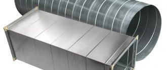
Before calculating the networks, you need to determine what they will be made of. Nowadays, products made of steel, plastic, fabric, aluminum foil, etc. are used. Air ducts are often made of galvanized or stainless steel; this can be organized even in a small workshop. Such products are easy to install and calculating such ventilation does not cause problems.
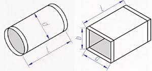
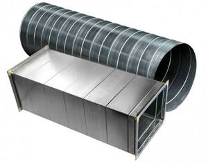
In addition, air ducts may vary in appearance. They can be square, rectangular and oval. Each type has its own advantages.
- Rectangular ones allow you to make ventilation systems of small height or width, while maintaining the required cross-sectional area.
- Round systems have less material,
- Oval ones combine the pros and cons of other types.
For an example of calculation, we will select round pipes made of tin. These are products that are used for ventilation of housing, office and retail spaces. We will carry out the calculation using one of the methods that allows us to accurately select the air duct network and find its characteristics.
Calculation of a duct heater
The calculation of an electric ventilation heater is carried out as follows:
P
= v * 0.36 * ∆ T
here v
- the volume of air passed through the heater in cubic meters per hour,
∆T
- the difference between the air temperature outside and inside, which must be provided to the heater.
This indicator varies between 10 - 20, the exact figure is set by the client.
Calculation of a heater for ventilation begins with calculating the frontal cross-sectional area:
Af=
R * p \3600 * Vp ,
here R
— volume of inlet flow, cubic meters per hour,
p
— density of atmospheric air, kg per cubic metre,
Vp
— mass air velocity in the area.
The mass velocity indicator is determined through the frontal area of the heat exchangers:
Vp
= R * p \3600 * A f.fact
For further calculation of the ventilation heater, we determine the amount of heat required to warm the air flow:
Q
=0.278 * W * c ( T p - T y),
here W
- warm air consumption, kg/hour,
Тп
- supply air temperature, degrees Celsius,
Тu
- street air temperature, degrees Celsius,
c
- specific heat capacity of air, constant value 1.005.
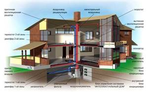
Maintaining a good indoor microclimate is a very important problem in the operation of any building. Removing polluted air and supplying clean and fresh air becomes the primary task in maintaining the required microclimate parameters. An additional function in this case is the preservation of heat in the premises.
This function has now begun to occupy a particularly important place in the design and operation of buildings, since many already constructed facilities do not meet modern regulatory documents and acts in this parameter. The most suitable solution to both problems is the use of modern ventilation systems
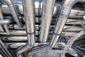
There are quite a large number of options for implementing these systems, each of which has its own pros and cons. But still there is one thing in them that unites them. This “something” is the ventilation pipes.
What data is needed to calculate duct parameters
To calculate the air duct, you must first determine two indicators:
- standards established for the supply of fresh flows per 1 m² of room per hour or air exchange rate, information is taken from regulatory sources. Using these data, knowing the volume of the room, you can easily determine the performance value of the ventilation system. Accordingly, the volume of air is calculated by multiplying the multiplicity by the volume of the room;
- according to sanitary standards. In this case, 60 m³ should be taken for each person permanently staying in the premises, and 20 m³ for a temporarily staying person.
The effectiveness of air purification in production depends on correct calculations
How to find the correct values
- About the minimum required air flow;
- About the maximum possible air flow speed.
- If the flow rate is higher than the specified limit, this will cause a drop in pressure. These factors, in turn, will increase energy consumption;
- Aerodynamic noise and vibration, if everything is done correctly, will be within normal limits;
- Ensuring the required level of tightness.
This will also improve the efficiency of the system and help make it durable and practical. Finding optimal network parameters is a fundamentally important point in design. Only in this case will the ventilation system last a long time, coping well with all its functions. This is especially true for large public and industrial premises.
What exactly to choose depends on your requirements, the priority of energy saving, and the very characteristics of the room. If you want to save energy, minimize noise and have the opportunity to install a large network, choose a rectangular system. If ease of installation is a priority or it is difficult to install rectangular-type structures in a room, you can choose products with a round cross-section.
Sc = L * 2, 778/V
The following formulas will help determine the actual area of the air ducts:
Algorithm for calculating the cross-section of air ducts
Calculation of the cross-section of air ducts involves determining the size of the air ducts depending on the flow rate of the air passed through. It is performed in 4 stages:
- Conversion of air flow to m3/s
- Choosing air speed in the duct
- Determining the cross-sectional area of the duct
- Determining the diameter of a round or width and height of a rectangular duct.
At the first stage of air duct calculation, the air flow rate G, usually expressed in m3/hour, is converted to m3/s. To do this, you need to divide it by 3600:
- G [m3/s] = G [m3/hour] / 3600
At the second stage, you should set the speed of air movement in the duct. The speed should be specified, not calculated. That is, choose the air speed that seems optimal.
The high air velocity in the duct allows the use of small cross-section ducts. However, the air flow will be noisy, and the aerodynamic resistance of the air duct will greatly increase.
Low air speed in the air duct ensures quiet operation of the ventilation system and low aerodynamic resistance, but makes the air ducts very bulky.
For general ventilation systems, the optimal air speed in the air duct is considered to be 4 m/s. For large air ducts (600x600 mm or more), the air speed can be increased to 6 m/s. In smoke removal systems, air speed can reach or exceed 10 m/s.
So, at the second stage of calculating air ducts, the air speed v [m/s] is set.
We recommend: What are multi-zone VRF air conditioning systems
At the third stage, the required cross-sectional area of the air duct is determined by dividing the air flow by its speed:
- S [m2] = G [m3/s] / v [m/s]
At the fourth, final stage, its diameter or the lengths of the sides of a rectangular section are selected for the resulting cross-sectional area of the air duct.
Basic formulas for aerodynamic calculations
The first step is to make an aerodynamic calculation of the highway. Let us remind you that the main air duct is considered to be the longest and most loaded section of the system. The fan is selected based on the results of these calculations.
Just don’t forget about linking the remaining branches of the system
It is important! If it is not possible to make connections on the branches of the air ducts within 10%, you need to use diaphragms. The diaphragm resistance coefficient is calculated using the formula:
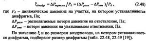
If the discrepancy is more than 10%, when a horizontal air duct enters a vertical brick duct, rectangular diaphragms must be placed at the junction.
The main task of the calculation consists of finding the pressure loss. At the same time, I select the optimal size of the air ducts and control the air speed. The total pressure loss is the sum of two components - pressure loss along the length of the air ducts (due to friction) and losses in local resistance. They are calculated using the formulas
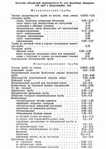
These formulas are correct for steel air ducts; for all others, an correction factor is introduced. It is taken from the table depending on the speed and roughness of the air ducts.
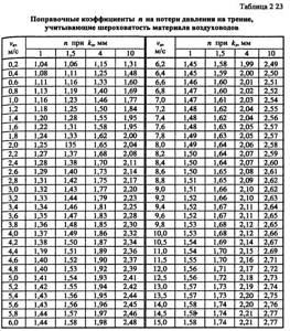
For rectangular air ducts, the calculated value is the equivalent diameter.
Let's consider the sequence of aerodynamic calculation of air ducts using the example of offices given in the previous article using formulas. And then we’ll show you what it looks like in Excel.
Calculation example
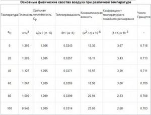
According to calculations, the air exchange in the office is 800 m3/hour. The task was to design air ducts in offices no more than 200 mm high. The dimensions of the room are given by the customer. Air is supplied at a temperature of 20°C, air density 1.2 kg/m3.
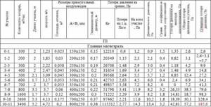
It will be easier if the results are entered into a table of this type
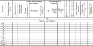
First we will do an aerodynamic calculation of the main line of the system. Now everything is in order:
We divide the main line into sections along the supply grilles. We have eight grates in the room, each with a capacity of 100 m3/hour. There were 11 sections. We enter the air flow at each section into the table.

- We record the length of each section.
- The recommended maximum speed inside the duct for office premises is up to 5 m/s. Therefore, we select the size of the air duct so that the speed increases as it approaches the ventilation equipment and does not exceed the maximum. This is done to avoid noise in ventilation. Let’s take an air duct of 150x150 for the first section, and 800x250 for the last section.
V1=L/3600F =100/(3600*0.023)=1.23 m/s.V11= 3400/3600*0.2= 4.72 m/s
We are satisfied with the result. We determine the dimensions of the air ducts and the speed using this formula in each section and enter them into the table.
- We begin calculating pressure losses. We determine the equivalent diameter for each section, for example the first dе=2*150*150/(150+150)=150. Then we fill in all the data necessary for the calculation from the reference literature or calculate: Re=1.23*0.150/(15.11*10^-6)=12210. λ=0.11(68/12210+0.1/0.15)^0.25=0.0996 The roughness of different materials is different.
- Dynamic pressure Pd=1.2*1.23*1.23/2=0.9 Pa is also recorded in the column.
- From Table 2.22 we determine the specific pressure loss or calculate R=Pd*λ/d= 0.9*0.0996/0.15=0.6 Pa/m and enter it in a column. Then at each section we determine the pressure loss due to friction: ΔРtr=R*l*n=0.6*2*1=1.2 Pa.
- We take local resistance coefficients from reference literature. In the first section we have a grille and an increase in the air duct in the sum of their CMC is 1.5.
- Pressure loss in local resistances ΔРм=1.5*0.9=1.35 Pa
- We find the amount of pressure loss in each section = 1.35+1.2=2.6 Pa. And as a result, the pressure loss in the entire line = 185.6 Pa. by that time the table will look like
Next, the remaining branches are calculated using the same method and linked. But we’ll talk about this separately.
Example of air duct calculation
As an example, let's calculate the cross-section of an air duct with an air flow of 1000 m3/hour:
- G = 1000/3600 = 0.28 m3/s
- v = 4 m/s
- S = 0.28 / 4 = 0.07 m2
- In the case of a round duct, its diameter would be D = root (4·S/ π) ≈ 0.3 m = 300 mm. The nearest standard duct diameter is 315 mm.
In the case of a rectangular duct, it is necessary to select A and B such that their product is approximately 0.07. It is recommended that A and B do not differ from each other by more than three times, that is, a 700x100 air duct is not the best option. Better options: 300x250, 350x200.
Manufacturers
For a long time, the leading role in the Russian air duct market was occupied by European manufacturers: the Polish company VTS Clima, companies from Sweden - Systemair (Kanalflakt) and Ostberg, German companies Wolter and Korf.
Today, Russian companies Arktos, NED, Moven, Venti LLC and a number of other companies that produce products of decent quality, in a large assortment of standard sizes of air ducts and fittings for them, compete with them. At the same time, the cost of Russian-made products is significantly lower than their European counterparts.
Formula for calculating the area of air ducts
The area of the air ducts is determined by multiplying the perimeter of the air duct cross-section by the length of the air duct:
- S = П·L, where П and L are, respectively, the perimeter and length of the air duct in meters.
It is important to remember the dimensions of the quantities in the formula above. Typically, the duct cross-section is specified in millimeters (for example, diameter 250 or section 500×250), and the length is specified in meters (for example, 5 meters). But it is necessary to substitute all values expressed in meters into the formula. Moreover, you must first calculate the length of the perimeter of the air duct section.
To simplify the task of calculating the area of air ducts, ready-made formulas for round and rectangular air ducts are used.
Summing up
The editors of Seti.guru hope that today's article was interesting and useful to our respected reader. If you have any questions, you can ask them in the discussions below, our team will be happy to answer them as soon as possible
If you have experience in installing ventilation systems or designing them (no matter whether positive or negative), we ask you to share it with other readers. This will be useful for novice home craftsmen taking their first steps in the field of ventilation. And finally, according to the already established good tradition, we suggest watching a short video on today’s topic, which will definitely be of interest to you
And finally, according to the already established good tradition, we suggest watching a short video on today’s topic, which will definitely be of interest to you.
Calculation of square meters (sectional area) of the air duct
The size of the ventilation pipe is influenced by many factors: flow speed, pressure on the walls, air volume. If you make calculations with an error, for example, reduce the cross-section of the main network, the speed of air masses will increase, noise will appear, pressure and electricity consumption will increase.
The calculation of the cross-sectional area of the duct is calculated using the following formula:
S = L × κ / ω, where:
- L – air flow, m³/h;
- ω – speed of air flow, m/s;
- κ – calculated coefficient equal to 2.778.
How to calculate diameter and length
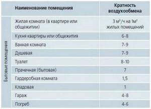
To independently calculate the diameter of the exhaust pipe, you need to know the size of the room and the rate of air exchange in the room. It can be selected for residential buildings according to the air exchange rate table:
Then perform the following calculations:
- Calculate the volume of each room by multiplying its three sizes.
- To determine the required volume of air, use the formula:
- All L values are rounded up so that the resulting numbers are multiples of 5.
- The inflow volume of each room is summed up.
- The standard speed value for residential premises is determined according to the table:
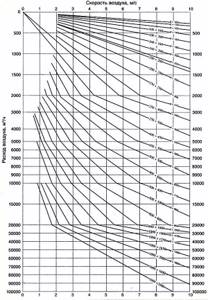
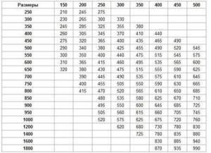
- Find the appropriate diameter of the ventilation pipes according to the diagram:
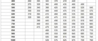
- The length of the outer section of the exhaust pipe is determined depending on its diameter according to the table, in which the column on the left represents the dimensions of the pipe width, and the cells indicate its cross-sectional area. The size of the air duct section introduced outside occupies the top line.
Calculation using the program
To calculate ventilation, you can use a special program. The optimal value of the supply air volume is taken here as the initial data, which is determined depending on the purpose of the room. The calculation also takes into account:
- average temperature inside and outside;
- geometric shape of air ducts;
- a manufacturing material that has different roughness and resistance to air flow.
Calculation of air speed in the duct
When calculating a ventilation system, one of the main indicators is the air exchange rate. In other words, how much air mass is needed to comfortably ventilate 1 m³ of a room in 1 hour. In this case, you can also refer to the development tables, but you should know that all the indicators in them are rounded, so more accurate data is obtained by doing your own calculations. The air exchange rate can be calculated using the formula:
N = V / W, where
- V – the amount of fresh air masses that enter the room in 60 minutes (m³/hour);
- W – room volume, m³.
You should know this! A comfortable air exchange rate for most domestic ventilation systems is 3-4 m/s.
You can carry out aerodynamic calculations and calculate the speed of air movement using the following formula:
ω = L / 3600 × S, where
- L – volume of air used per 1 hour;
- S – cross-sectional area of the air duct.
Air exchange standards for an apartment
Basic calculation requirements
When determining the final parameters of air ducts, it is necessary to take into account that determining the area of air ducts must ensure that:
- The temperature regime in the room is ensured. Where there is excess heat, its removal is provided, and where there is a deficiency, its losses are minimized.
- The speed of air movement does not in any way reduce the level of comfort of people in the room. Air purification is required in work areas.
- Harmful chemical compounds and suspended particles present in the air are present in a volume corresponding to GOST 12.1.005-88.
For individual rooms, a prerequisite for selecting the area of air ducts is to constantly maintain pressure and exclude air supply from outside.
When calculating line resistance, pressure loss is taken into account. In order for the flow of air mass to overcome resistance during movement, appropriate pressure is required
The category of premises where backup is required includes basements, as well as premises in which harmful substances can accumulate.
This is interesting: Air conditioning - do-it-yourself installation and connecting the system
Calculation of duct network resistance
Air flows experience resistance when transported through pipes, especially for pipes with a rectangular cross-section. To ensure normal system performance, you need to select a fan of appropriate power. It is difficult to manually determine these parameters on your own; in the project team, all calculations are performed using a program.
You should know this! For apartments with an area of 50−150 m², the standard resistance parameters of the air exhaust system range from 75 to 100 Pa for a flow speed of 3−4 m/s.
The resistance is not affected by the number of rooms served by the ventilation system; the value of the coefficient depends on the structure and length of the communication.
We recommend: Sliding wardrobes – a whim or a necessity?
Flow velocity directly dependent on resistance
Calculation methods for shaped products
An error in choosing the cross-sections of the shaped parts can lead to improper air flow circulation even with an error-free design. Many manufacturers provide nomograms in the explanatory note to the project. These are graphical calculations of a function for several variables, presented in the normative literature.
Engineering assistance for calculating air ducts says that there is a way to apply a ruler, with the help of which functional dependencies are worked out without using formulas. The cross-sectional area of the duct fittings, which is capable of balancing the noise level in the system, is taken from the monograms.
Follow these steps to determine the pipe dimensions for a branch or turn:
- find on the monogram the point of intersection of the air flow moved per hour and the optimal speed line for a given area;
- not far from this point, find the value of the suitable diameter.
Using the nomogram, it is easier to calculate the area of shaped parts of air ducts, and the decrease in pressure in the system at a set flow rate is specified.
Pressure loss on straight sections
To calculate the performance of ventilation equipment, you can simply add up the required amount of air masses and select a model that fits these parameters. However, the product passport does not take into account the air duct network. Therefore, when connecting it to the system, the performance will drop significantly depending on the resistance parameter in the pipeline. To determine the pressure drop in the system, it is necessary to clarify its decrease in flat areas, rotary and connecting elements. The pressure drop on level areas is determined by the formula:
Р = R × L + Еi × V2 × Y / 2, where
- R – specific pressure loss caused by friction during air movement, Pa/m;
- L – length of the straight section of the air duct, m;
- ω – air speed, m/s
- Y – density of air masses, kg/m³;
- Ei is the sum of pressure losses due to local resistances (branches, transitions, gratings, etc.), data can be taken from the reference book.
Straight ventilation section
Installation
Installation of metal air ducts is carried out according to the following scheme:
- assemble air ducts into separate sections;
- carry out marking of fastening points on the building envelope;
- install fasteners using a construction and assembly gun or welding equipment;
- fasten the sections into the system using traverses or clamps for suspension;
- all parts are joined using a seam or welded joining method.
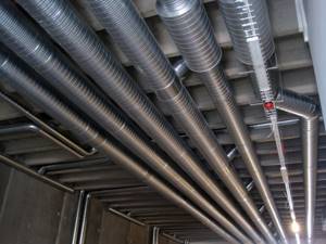
Wall and ceiling mounting
Air ducts are attached to the wall or ceiling, that is, in a vertical or horizontal position. Depending on the position of the system section, the material of the base structure and the dimensions of the channel, different fastening elements are used during installation: Z-shaped and L-shaped profiles.
For example, for fastening to brick walls or to reinforced concrete surfaces of horizontal sections, angle-shaped brackets with a hole at one end for suspension are used. A rubber seal is installed between the protruding part of the bracket and the wall, ensuring a tight fit and reducing noise from vibration. The length of the bracket itself depends on the size and weight of the ventilation duct.
Installation of vertical sections of the ventilation pipe using a mounting crossbar or clamps. The traverse is a supporting part, and lateral movements are limited by special pins.
How to collect correctly?
Before installation, air ducts are assembled in sections no longer than 15 m. For joining round metal pipes, different types of connections are used:
- flanged - the air ducts are attached to each other using a flanging method;
- bandage - use sheet steel strips and special mastics for sealing;
- using couplings and nipples - manufactured without sealing gaskets and with rubber seals;
- bell-shaped - connected by inserting the straight end of one air duct into the bell-shaped end of the other.
Rectangular galvanized pipes for ventilation are joined using;
- flanges - connected by spot or conventional welding, the welding areas are painted with fire-resistant enamel;
- tires - a special galvanized part in the form of corner inserts.
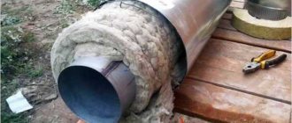
Thermal insulation
The installation of thermal insulation on sections of air ducts located outside the room or in unheated buildings is necessary to ensure uninterrupted operation of the entire ventilation system as a whole. Thermal insulation functions include:
- preventing the appearance of condensate on the outer and inner surfaces of pipes. A high level of humidity during the formation of condensation leads to corrosion damage to the walls of pipelines and the formation of mold on them;
- ensuring fire safety. The use of non-combustible materials increases the fire resistance of the ventilation system as a whole and especially the places where pipes for ventilation pass through the ceilings and roof of a private house;
- reduction of noise and vibration. Turbulence of the air flow and the operation of ventilation equipment create vibration and acoustic effects. A layer of insulating material will reduce the noise level and vibration of the ventilation system elements.
Thermal insulation of all types of air ducts, except sandwich pipes, is carried out in two ways: from inside and outside the pipeline. Mineral or fiberglass wool is used for these purposes. To strengthen the surface fibers, heat-resistant adhesives are used that do not emit toxic gases when heated or ignited.
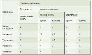
Recommended air speed values in the ventilation system, m/s
| Apartments | Offices | Industrial premises | |
| Supply grilles | 2.0-2.5 | 2.0-2.5 | 2.5-6.0 |
| Main air ducts | 3.5-5.0 | 3.5-6.0 | 6.0-11.0 |
| Branches | 3.0-5.0 | 3.0-6.5 | 4.0-9.0 |
| Air filters | 1.2-1.5 | 1.5-1.8 | 1.5-1.8 |
| Heat exchangers | 2.2-2.5 | 2.5-3.0 | 2.5-3.0 |
How to calculate the area of material used
Calculation of the optimal air duct area is directly dependent on factors such as the volume of air supplied to one or more rooms, its speed and air pressure loss.
At the same time, the calculation of the amount of material required for its manufacture depends both on the cross-sectional area (dimensions of the ventilation channel), and on the number of rooms into which it is necessary to pump, and on the design features of the ventilation system.
When calculating the cross-sectional area, it should be borne in mind that the larger it is, the lower the speed of air passage through the air duct pipes.
At the same time, there will be less aerodynamic noise in such a highway, and the operation of forced ventilation systems will require less electricity. To calculate the area of air ducts, you need to apply a special formula.
To calculate the total area of material that needs to be taken to assemble air ducts, you need to know the configuration and basic dimensions of the system being designed. In particular, to calculate for round air distribution pipes, quantities such as the diameter and total length of the entire line will be required. At the same time, the volume of material used for rectangular structures is calculated based on the width, height and total length of the air duct.
When making general calculations of material requirements for the entire highway, it is also necessary to take into account bends and half-bends of various configurations. Thus, correct calculations of a round element are impossible without knowing its diameter and angle of rotation. When calculating the area of material for a rectangular outlet, components such as width, height and angle of rotation of the outlet are involved.
It is worth noting that each such calculation uses its own formula. Most often, pipes and fittings are made of galvanized steel in accordance with the technical requirements of SNiP 41-01-2003 (Appendix N).
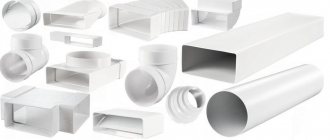
Location and features of plastic ventilation
Installation of plastic ventilation begins with drawing up a diagram. When developing it, the location of the hood is noted and holes are provided for removing condensate in the exhaust ventilation ducts. If the pipelines are very long, it is planned to install additional fans to improve air pressure. The diagram shows the installation locations of check valves.
To install you will need the following:
- roulette;
- pencil;
- ruler;
- side cutters;
- brush for applying sealant;
- hand gloves (to protect against cuts);
- hacksaw;
- silicone sealant;
- sandpaper;
- special clamps for fixing pipes;
- drill or hammer drill with drills;
- screws and dowels;
- plastic air ducts;
- shaped elements.
Installation sequence:
- At the preliminary stage, calculations are carried out, determining the cross-section and length of ventilation ducts, the need for connectors and adapters. The total number of outlet openings is also specified.
- Ventilation ducts are cut with a hacksaw so that the length coincides with the calculated one. The cut area is treated with sandpaper to eliminate irregularities and burrs.
- The pipes are connected to each other using special connectors or simply by putting one end on the other. If the latter method is used, then the element is buried 50 mm in length. In any case, the joint area is pre-coated with silicone sealant.
- One edge of the pipeline is attached to the hole in the ventilation duct in the wall.
- To check the tightness, turn on the fan. Assess the proper operation of the check valve and the absence of air leaks at the connections.
If a branched system is being assembled, then all the parts are first assembled on the floor into a single structure. Then they are connected to the main ventilation of the house and checked for proper operation.
Sanitary requirements of regulatory documents
The minimum amount of air supplied and removed from the rooms of the cottage by the ventilation system is regulated by two main documents:
- “Residential multi-apartment buildings” - SNiP 31-01-2003, paragraph 9.
- “Heating, ventilation and air conditioning” - SP 60.13330.2012, mandatory Appendix “K”.
We recommend: Artificial decorative home waterfall in the country: how to make a pond with a waterfall in the garden and in the yard from wild stone, diagram without a pump
The first document sets out sanitary and hygienic requirements for air exchange in residential premises of apartment buildings. There are 2 types of dimensions used - air mass flow rate by volume per unit of time (m³/h) and hourly multiplicity.
Reference. The air exchange rate is expressed by a number indicating how many times within 1 hour the air environment of the room is completely renewed.

Ventilation is a primitive way to renew oxygen in a home
Depending on the purpose of the room, supply and exhaust ventilation should provide the following flow rate or number of air mixture updates (multiplicity):
- living room, children's room, bedroom - 1 time per hour;
- kitchen with electric stove – 60 m³/h;
- bathroom, bathtub, toilet – 25 m³/h;
- for a furnace with a solid fuel boiler and a kitchen with a gas stove, a multiplicity of 1 plus 100 m³/h is required during the operation of the equipment;
- burning natural gas - three times renewal plus the volume of air required for combustion;
- pantry, dressing room and other utility rooms - multiplicity 0.2;
- drying or washing room – 90 m³/h;
- library, study – 0.5 times per hour.
Note. SNiP provides for reducing the load on general ventilation when equipment is not working or people are absent. In residential premises, the multiplicity is reduced to 0.2, in technical premises - to 0.5. The requirement for rooms where gas-using installations are located remains unchanged - an hourly one-time update of the air environment.

The release of harmful gases due to natural draft is the cheapest and easiest way to renew the air
Clause 9 of the document implies that the exhaust volume is equal to the inflow volume. The requirements of SP 60.13330.2012 are somewhat simpler and depend on the number of people staying in the room for 2 hours or more:
- If 1 resident has 20 m² or more of apartment area, the rooms are provided with a fresh influx of 30 m³/h per 1 person.
- The volume of supply air is calculated by area when there are less than 20 square meters per resident. The ratio is as follows: 3 m³ of inflow is supplied per 1 m² of housing.
- If ventilation is not provided in the apartment (there are no vents or opening windows), 60 m³/h of clean mixture must be supplied to each resident, regardless of the square footage.
The listed regulatory requirements of two different documents do not contradict each other at all. Initially, the performance of the general ventilation system is calculated according to SNiP 31-01-2003 “Residential buildings”.
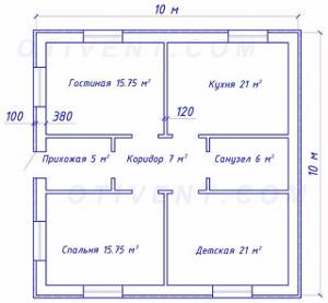
The results are checked against the requirements of the Code of Practice “Ventilation and Air Conditioning” and, if necessary, adjusted. Below we will analyze the calculation algorithm using the example of a one-story house shown in the drawing.
Section and dimensions
The choice of cross-sectional dimensions should be based on the standard value of the flow velocity. So for residential buildings this figure in branches is 4 m/s, for public buildings - 5 m/s, for industrial purposes - 9 m/s. At other speeds, the hum in the system will disturb people.
Standard dimensions according to VSN 353-86 and SNiP 41-01-2003 are:
- for round ducts: 100, 125, 160, 200, 250, 315, 355, 400, 450, 500, 560, 630, 710, 800, 900, 1000, 1120, 1250, 1400, 1600, 1800 and 2000 mm;
- for rectangular and square air ducts, the cross-sectional lengths of the walls vary from 100 mm to 3200 mm.
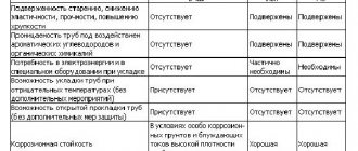
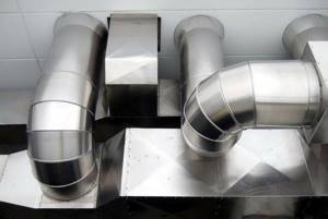
Which is better, round or rectangular?
The choice of using round or rectangular air ducts for the construction of a ventilation system is based on parameters such as the area of the building, the location of the ducts and their configuration, and the requirements for the noise level in the room.
The design also takes into account the temperature and humidity conditions and the decisions made on interior design. In rectangular ventilation systems, air leakage is possible due to the use of two flanges during installation; sections of round air ducts are connected using one fitting, so they are more airtight.
Round channels are much easier to clean than rectangular ones; they are less noisy, but look worse in the interior.
However, they are more difficult to hide behind decorative elements in the room.
Connecting elements and fittings
To connect sections of air ducts and connect ventilation equipment, various types of hardware parts and fittings are used. The list of such elements consists of:
- nipple - a part designed to ensure sealing of air duct connections. Typically, nipples have left and right-hand threads at the same time, which allows you to fasten two ends of pipes at the same time;
- couplings - a connecting element of air ducts with a circular cross-section;
- bends 30º, 45º, 60º, 90º - used to change the direction of air movement at a certain angle when avoiding obstacles during installation of the system;
- round transition - used for joining pipes of different diameters, connecting shaped elements with a circular cross-section;
- tee - parts for connecting two branches of pipelines with the main line;
- inserts of round or rectangular cross-section - replace the tee and allow you to connect elements into the finished structure;
- plugs - regulate air flow, protect the ventilation system from foreign objects and debris;
- ducks (S-shaped outlet) - helps to change the level of the air ducts;
- round umbrella - protect the outer part of the air duct from precipitation;
- crosses - parts for connecting three branches at right angles into one common air duct;
- transition from a rectangular section to a round one - used to connect parts of a ventilation system of different sizes.
Which section is used where?
Models with a rectangular cross-section are not the most ideal option for an air duct, this is due to unsatisfactory aerodynamics and more complex installation. However, with their help you can save space, since the walls of the pipe are as close to the surfaces as possible without additional fasteners. This advantage puts rectangular ducts in first place for arranging ventilation in residential premises and small offices.
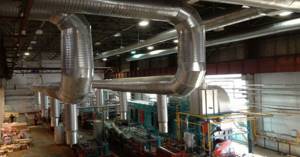
For an industrial ventilation system, practical and easy-to-use round air ducts are more suitable for exhaust hoods.
They have less air resistance and have a high level of rigidity and tightness. In addition, round exhaust pipes are less material-intensive, therefore, with the same throughput, they are cheaper, and they are much more profitable to use on large objects.