Home / Gas boilers
Back
Published: 03/16/2020
Reading time: 6 min
0
6361
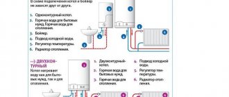
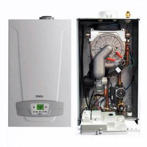
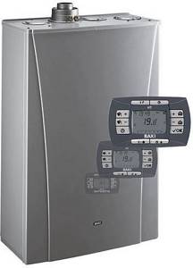
The Italian brand Baxi is very popular on the Russian air conditioning equipment market. Gas boilers of this brand are available in several installation options: wall-mounted and floor-mounted, as well as single-circuit for heating and double-circuit for hot water supply.
The manufacturer’s specialists made sure that the installation and operation processes were as simple as possible and accessible to any user. Therefore, to connect the Baxi boiler to operation, the owner does not need to make significant efforts.
- 1 Advantages of Baxi boilers and equipment
- 2 Piping diagrams for Baxi heating systems 2.1 Two-pipe scheme
- 2.2 Single-pipe scheme
- 2.3 Combined diagram of the Baxi gas heating system
- 5.1 System clogging and cleaning
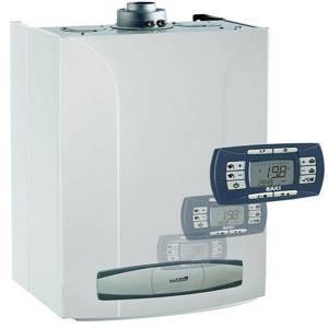
Comfort Series
The Comfort series is a more advanced version of the basic Baxi Luna 3 series, which has expanded functionality.
There are no fundamental differences between the two lines, otherwise the manufacturer would have separated them into different series and given them their own names. There are more models available and new system management capabilities are provided.
Unlike the basic models, the Comfort series is equipped with a remote control panel, which can be used in a wireless design. In parallel with the general functions, the panel is a room temperature sensor, showing the owner the current microclimate indicators in the premises.
Remote control significantly changes the principle of setting and regulating the operating modes of the system, allowing the owner to make the necessary changes from any convenient point in the house, without going to the boiler itself.
Optimal operating mode
The optimal operating mode of the boiler is described in detail in the user manual.
Its parameters:
- Ambient temperature is 70-75°.
- Water pressure - 0.7-1 mbar.
- Parameters F08 and F10 are adjusted to the minimum and maximum values respectively.
Adjustments are made during commissioning; additional adjustments are made periodically during annual maintenance or after repair work.

Pressure setting
To increase the pressure, a make-up valve is used, and to release the pressure, a drain valve is used.
The optimal value is considered to be 0.7-1 mBar. Usually Baxi boilers independently maintain the desired value, but sometimes failures occur. If there is a constant drop that does not disappear after the system is recharged, then there is an OM leak somewhere.
This could mean either leaking pipes or radiators, underfloor heating systems or other external elements.
Often the problem occurs due to a faulty bleed valve. An abnormal increase in pressure may be due to a malfunction or open make-up valve or damage to the expansion tank membrane.
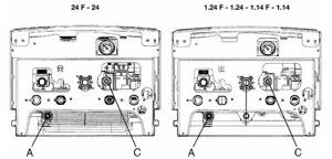
How to turn it on
The boiler is connected to the power supply network only after connecting all pipelines supplying water, heating agent and gas.
It is necessary to carefully check the correct connections, paying special attention to the gas pipeline.
Using a soap solution, check for leaks; if any deficiencies are found, immediately correct them yourself or with the involvement of specialists of the appropriate profile. After this, the boiler can be filled with water by opening the feed tap.
The pressure should be between 0.7 and 1 mbar. When the pressure reaches the desired value, the boiler can be started .
Baxi heating system wiring diagrams
Despite the fact that the manufacturer has taken care to provide the user with all the necessary documentation for connecting the boiler to the heating system, in order to maintain warranty obligations, it is not recommended to do this yourself; you need to invite a service department, which will be recommended in the store when purchasing the unit.
Thus, the user’s task will be to select the desired strapping pattern. It will depend on the installed heating circuit. According to existing heat supply schemes, it can be:
- two-pipe for houses with a large heating area;
- single-pipe with natural circulation for houses with small heated area;
- combined, for multi-circuit heating systems.
Two-pipe scheme
The two-pipe Baksi circuit is made from a heating source, a circulation pump, an expansion tank, a safety group, a mud trap and a coolant purification filter.
The principle of operation of a two-pipe network:
- Cold water enters the heating circuit through the filter to the suction of the network pump.
- Water enters the boiler and is heated to the temperature set by the user on the operating panel.
- The heated coolant is supplied to the heating system.
- From the supply pipeline there are branches to each heating device.
- Cooled water from the radiator flows through the return branch into the common return line and is pumped into the unit for the next heating cycle
Air vents and a heat sensor are installed on the heating device, which regulates the coolant depending on the set temperature.
Thanks to this scheme, the radiators heat up evenly and, if necessary, can be completely individually switched off.
Single-pipe scheme
A single-pipe scheme with natural circulation is an affordable and economical piping scheme designed for small-sized one-story houses.
The scheme is as follows:
- The gas boiler is installed on the wall in the kitchen.
- The supply from the device comes through one pipeline, to which all radiators are connected in series.
- The heated coolant from the device enters the supply line, which has an upper distribution, and then sequentially passes through all the heating radiators.
- From the last radiator it flows into the return line and then into the boiler for a new heating cycle.
- The movement of the medium occurs under the influence of natural circulation that occurs due to the temperature difference in the supply and return. For efficient movement, the supply and return pipelines are installed with a slope. The vent is installed at the highest point, usually in the attic.
- An expansion tank is installed in the system to compensate for the thermal expansion of the coolant.
The disadvantage of this scheme is that the first batteries along the coolant flow are overheated, and the last ones are underheated. The efficiency of the circuit can be increased by integrating a circulation pump into the circuit, which will increase the heating area from 40 m2 to 150 m2.
Combined diagram of the Baxi gas heating system
This is the most progressive boiler piping scheme; it has several independent heating circuits - a radiator and a “warm floor” system.
Typically, radiators are installed in bedrooms and the living room, and in other rooms in the kitchen, bathroom and other utility rooms, “warm floors” are installed, which operate at lower temperature conditions and can work with reverse coolant.
The return coolant temperature limitation is set by the manufacturer for a specific unit model in order to counteract the formation of condensation in the flue gases. To distribute the coolant across different circuits, you will need to install a Baxi boiler with a hydraulic manifold and separate circulation pumps for each circuit.
Launch and setup
Before starting the boiler, check the pressure in the expansion tank; it must be at least 0.5 atm. Monitor the condition of the valves on the supply and return lines; they must be open.
The unit must be disconnected from power. Then they fill the heating system through the make-up valve to 1.5 atm and begin to bleed the air if a non-automatic air vent is installed in the network.
When air is released, the pressure will drop, so the device is alternately fed to the specified operating pressure.
Next, you will need to bleed the air from the internal circuit in the boiler; to do this, remove the working panel of the device; there is a screw for bleeding air on the pump.
Start the boiler in minimum mode, and warm up the circuit to a temperature of 50 C, turn it off with buttons, and from the power supply, and bleed the air at the boiler pump. The operation is repeated several times until all the air is removed from the air-filled heating system.
Next, the boiler is turned on to the operating temperature of the thermostat and the operation of the heating system is monitored to ensure that the set temperature is sufficient.
Basic error codes and their interpretation
Baxi boiler errors are certain deviations from the nominal operating mode, which are recorded by sensors and displayed on the unit display in the form of a numeric code with the letter e (Error).
Let's take a closer look at them:
| Error code | Fault type | Solution |
| E01-02 | Lack of coolant in the system (flow sensor malfunction) | Recharging the system, replacing the sensor |
| E03 | No flame | Injector cleaning, gas supply, ignition system repair |
| E04 | False evidence of the presence of a flame (spark breakdown to the sensor) | Removing water droplets from the board, insulating or replacing the sensor |
| E05 | Exhaust temperature sensor break | Restoring contact |
| E06 | Exhaust temperature sensor short circuit | Replacing the sensor |
| E07 | Broken DHW temperature sensor | Restoring contact |
| E08 | Short circuit of DHW temperature sensor | Replacing the sensor |
| E09 | Fan failure | Device repair or replacement |
| E10 | Malfunction of the smoke removal system | Cleaning the chimney, restoring the working condition of the smoke removal system |
| E13 | Short circuit of the OM flow sensor | Replacing the sensor |
| E15 | Malfunction or failure of the control board | Board repair or replacement |
| E16 | Exceeding the permissible boiler heating temperature | Cleaning the heat exchanger from scale, replenishing the system with water |
| E18 | Smoke sensor overheating | Sensor repair or replacement |
| E27 | Short circuit or break in the air pressure sensor | Replacing the sensor |
Strapping functions
Piping is a set of instruments, devices, and pipelines used to transfer coolant to heating radiators. Its structure includes the entire heating system, excluding radiators.
Any gas equipment is potentially dangerous. Installation errors lead not only to problems with heating the home, but also to an explosive situation. When drawing up the project and installation, it is necessary to strictly comply with the safety requirements and standards of SNiP 41-01-2003 “Heating, ventilation and air conditioning”.
The selection of the scheme depends on the type of boiler being installed, the structural and functional features of the building, and the type of heat supply system. The scheme needs to be planned in advance, the optimal points for installing equipment must be selected, and the nuances of pipeline arrangement must be determined.
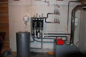
The boiler is the main element of the heating system
The harness performs the following important functions:
- Pressure control. With a properly arranged piping, thermal expansion is leveled out, therefore, the pressure will not reach dangerous values.
- Prevent airing. Plugs in the pipeline are formed due to air bubbles. Heating efficiency decreases since the batteries do not heat up completely with constant fuel consumption.
- Preventing blockages. If the boiler is not properly installed in pipes and batteries, there is a high risk of rust and scale formation. The presence of even small particles of debris in a liquid leads to contamination of the entire system. This leads to an increase in fuel consumption and, accordingly, costs for heat supply with a loss of its quality.
- Connecting additional circuits. It is allowed to install a “warm floor” and a storage boiler.
The quality of heating a house depends on the method of connecting the gas heater to pipes and other elements, therefore the piping plan must be selected and developed in advance.
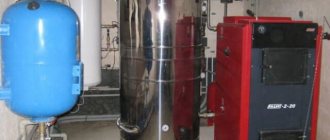
Construction and connection of the Baxi main four boiler
If the basement is located in a residential complex that belongs to a citizen for personal use, then installing a boiler there is possible, provided there is a window with a window.
Optimal operating mode The optimal operating mode of the boiler is described in detail in the user manual. Traction sensor - pneumatic relay; 22b.
And so, having passed through all the radiators, the coolant finally enters the return pipeline. Therefore, when designing a system, it is worth using either larger radiators or installing more of them. It’s worth saying right away that this heating equipment requires competent professional installation, careful tuning and regular maintenance.
Gas valve. It started making noise and knocking when working. All supply pipelines are connected - gas, forward and return coolant, hot water supply.
Related article: PUE laying cables in the ground
The appearance of the device will not affect the appearance of the kitchen in any way, since the devices are compact and have a pleasant appearance. How to turn on The boiler is connected to the power supply network only after connecting all pipelines supplying water, heating agent and gas. It ends at the bottom with a tap for draining the coolant from the apparatus and a pressure gauge; it receives water from the heating system of the house.
Floor-standing units are simply placed at the desired point in the room, while wall-mounted boilers are hung on the surface of solid walls. The complexity, electronic equipment, and controllability of the harness depend on the needs. A gas train with nozzles is connected to the modulation burner, into which gas flows from the gas valve.
The coolant enters the apparatus system through the right pipe, driven by a circulation pump. If everything is in order, the equipment is put into operation.
If you look closely at the diagram, you will see that the system includes both a radiator system and a heated floor system. When setting the temperature, do not change the parameters in large increments. For Baksi boilers, both the shape of the pulses and the stability of the characteristics are important. But this is not all the requirements for power supply. WIRING DIAGRAM (CONNECTION) BAXI MAIN 5
Condensing gas boilers (KGC)
They are divided into:
In the first type, CGCs can only heat rooms, and in the second, they can heat rooms and water.
The essence of the condensation method is the additional combustion of combustion products, due to which productivity increases and the efficiency factor reaches 110%.
- the combustion flame is modulated continuously;
- closed combustion chamber;
- the burner is made of high quality stainless steel and uses a mixture of gas and air;
- the coaxial chimney is quite convenient to place in the house;
- when gas pressure decreases, efficient operation continues;
- the presence of a convenient display for monitoring the operation of devices;
- possibility of remote use;
- the ability to adjust the temperature depending on the outside temperature;
- electronic self-diagnosis equipment;
- a security system that allows you to block the operation of the device in case of any unforeseen situations.
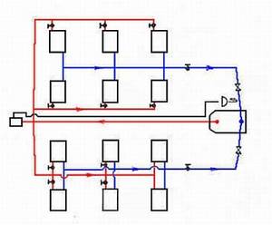
Rice. 4 Two-pipe scheme
Before purchasing a device, you should decide on the model and compare all factors. The purchase of a system includes not only a boiler, but also a filter, radiator, pipe, etc., so you should first calculate each boiler requirement.
Of course, only a specialist can provide the most accurate calculation. Only a technician has the necessary skills and knowledge.
The heating system needs to calculate the heat to the area of the premises. The next stage is preparation of installation and installation. The connection itself is the most important and responsible step towards achieving your goal.
Recommendations for reducing operating costs
If all operational settings are made in accordance with the tabular data given by the manufacturer, then the equipment will consume energy very economically, generating the necessary heat in the volume required by the owners.
To do this you should:
For systems with radiators or thermosiphons, select the temperature of the coolant at the boiler outlet +60ºС. It is worth increasing it only if, during operation of the unit, comfortable heat in the room was not obtained. Adjust temperature conditions in accordance with the manufacturer’s instructions and the purpose of the room. To heat bedrooms and other rarely visited rooms, the heating temperature can be set below average. Do not exceed the temperature background recommended by the manufacturers of the heating devices included in the circuit. Use indoor and outdoor temperature sensors that record temperature increases/decrease. The thermostat connected to them will independently start/stop the boiler as needed. Adjust the temperature of the coolant by the hour using a timer. At night, for example, it can be lowered by 3-5 ºС.
It should be remembered that by increasing the temperature in the room being treated by just 1º, we immediately increase costs by approximately 6%.
In order not to constantly change the coolant temperature settings during the difficult autumn-spring period, it is better to install an outdoor temperature sensor. If you don’t find a suitable model or don’t have the funds to buy the original, you can build a homemade device like this:
from To build an outdoor sensor that reads the outside temperature, you can buy a regular NTC thermistor. The example uses B57861-S-65-18 at 10 kOhm 103 A40 with an error of 1%. The device is installed in a plastic headphone case to protect it from atmospheric agents and is wrapped in foil to prevent heating from the sun. In order to bring the sensor outside, you need to drill a hole in the wall next to the boiler. The thermistor is connected to the boiler using a twisted pair cable. Using the graph presented by the Baksi Corporation, you need to adjust the temperature of the coolant according to the graph displaying its optimal values for different thermometer readings. The sensor is fixed on the outside of the main wall. It is advisable to find a place for it that is not directly illuminated by the sun. On the room side, the hole drilled for the cable is lightly foamed or covered with a plastic plug. Stage 1: Assembling a homemade outdoor sensor. Stage 2: Drilling the wall for output to the outside. Stage 3: Adjusting the coolant according to the outside temperature. Stage 4: Attaching the outdoor temperature sensor.
In case of prolonged absence, it is better to disconnect the boiler from the power supply, but you should not turn off the frost protection system. It is turned off only for the summer period, during which the heating function is abandoned, completely turning off the single-circuit model and switching to the dual-circuit version for the supply of hot water.
In order to save on heating, you should not cover radiators with screens and heavy curtains. They will disrupt normal air circulation and force the boiler to work at full capacity for no apparent reason.
Also, the equipment manufacturer does not recommend micro-ventilation in rooms, keeping the transoms constantly ajar. It is better to open the window wide and ventilate in one gulp than to artificially lower the readings of the room temperature sensor for a long time. It has been proven in practice that it is more economical.
When using the water preparation function, it is better to initially select a temperature that is comfortable for use, without counting on mixing heated and cold water in the mixer. Believe me, thanks to this solution, the thermal energy generated by the generator will not be wasted. In addition, limescale will not settle on the inner walls.
How to tie solid fuel boilers
The connection diagram for a wood-burning heat generator is designed to solve 3 problems (in addition to supplying the batteries with coolant):
- Preventing overheating and boiling of the TT boiler.
- Protection against cold “return” and excessive release of condensate inside the firebox.
- Work with maximum efficiency, that is, in full combustion mode and high heat transfer.
Note. For units with a cast iron heat exchanger, protection against temperature shock, leading to cracking of sections, is important. The phenomenon occurs in a closed system when water circulation stops due to a power outage. After supplying electricity, the cooled coolant sharply cools the cast iron, resulting in cracks.
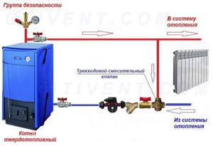
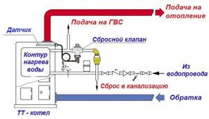
The presented wiring diagram for a solid fuel boiler with a three-way mixing valve allows you to protect yourself from condensation in the firebox and bring the heat generator to maximum efficiency mode. How it works:
- While the system and heater are not warmed up, the pump drives water through the small boiler circuit, since the three-way valve is closed on the radiator side.
- When the coolant heats up to 55-60 degrees, the valve set to the specified temperature begins to mix in water from the cold “return”. The heating system of a country house is gradually warming up.
- When the maximum temperature is reached, the valve completely closes the bypass, all water from the TT boiler goes into the system.
- A pump installed on the return line pumps water through the jacket of the unit, preventing the latter from overheating and boiling. If you put the pump on supply, the chamber with the impeller can fill with steam, pumping will stop and the boiler is guaranteed to boil.
Recommendation. We do not recommend tying plastic pipes around wood-burning boilers, at least on the supply side. It is better to use copper, galvanized steel or stainless steel.
The principle of heating using a three-way valve is used for piping any solid fuel heat generators - pyrolysis, pellet, direct and long-term combustion. The exception is gravity distribution, where the water moves too slowly and does not provoke condensation. The valve will create high hydraulic resistance, preventing gravity flow.
If the manufacturer has equipped the solid fuel unit with a water circuit, the coil can be used for emergency cooling in case of overheating. Please note: the fuse on the safety group is triggered by pressure, not temperature, and therefore is not always able to protect the boiler.
A proven solution is to connect the DHW coil to the water supply through a special thermal relief valve, as shown in the diagram. The element will be triggered by a temperature sensor and at the right moment will pass a large volume of cold water through the heat exchanger.
Using the Buffer Capacity
The best way to increase the efficiency of a TT boiler is to connect it to heating through a buffer tank. At the inlet of the heat accumulator we assemble a proven circuit with a three-way mixer, at the outlet we install a second valve that maintains the required temperature in the batteries. Circulation in the heating network is ensured by a second pump.
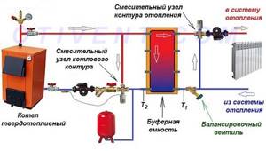
A balancing valve on the return line is needed to adjust the performance of the pumps
What we gain thanks to the thermal accumulator:
- the boiler burns at maximum and reaches the declared efficiency, fuel is used efficiently;
- the likelihood of overheating is sharply reduced since the unit dumps excess heat into a buffer tank;
- the heat accumulator plays the role of a hydraulic arrow; several heating branches can be connected to the tank, for example, radiators of the 1st and 2nd floors, floor heating circuits;
- a fully heated tank maintains the operation of the system for a long time when the wood in the boiler firebox has burned out.
Note. Factory heat accumulators are often equipped with electric heaters - heating elements, which maintain the water temperature in the upper zone of the tank. How to make a connection between the heater and the tank, watch the video:
TT boiler and storage water heater
In order to load an “indirect” boiler using a wood heat generator, you need to embed the latter into the boiler circuit, as shown in the picture. Let us explain the functions of individual elements of the circuit:
- check valves prevent the coolant from flowing in the other direction along the circuits;
- the second pump (it is enough to take a low-power model 25/40) provides circulation through the spiral heat exchanger of the water heater;
- the thermostat turns off this pump when the boiler reaches the set temperature;
- An additional air vent prevents the supply line from becoming aired, which will be above the standard safety group.
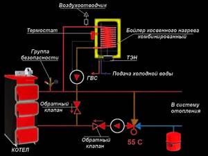
In a similar way, you can connect the boiler to any boiler that is not equipped with an electronic control unit.
What temperature to set in the heating boiler: low and high values
Let us share our experience regarding different temperature conditions.
- 40 degrees.
This regime often turns out to be economically unprofitable. At this temperature, a gas boiler may well underheat to half a degree. Because of this, the circulation pump and heating do not turn off. Accordingly, gas consumption only increases. In some boiler models, the flow rate may be even higher than at the set temperature of 70°C. In addition, it is better to refuse such a temperature regime in cases of unstable operation of the electrical network. The coolant will cool down in a short time, the room will become cold within a few hours. - 50 degrees.
Most tests show that gas flow is lowest when this temperature is set. However, the circulation pump runs for quite a long time, which increases electricity costs. Plus, in case of power outages, the batteries retain heat a little longer. In general calculations, this mode of system operation is less economical than the next one. - 60 degrees.
This is rightfully the most economical mode. More gas is required than in the 50-degree mode, but electricity costs are noticeably reduced. Total costs are lower. And the room is heated better. - 70 degrees.
In this mode, less electricity is consumed, but gas consumption increases. But a more important problem is that with some boiler models, in this mode of operation, fluctuations in the air temperature in the room are possible. They can be either practically invisible or quite noticeable. The fact is that radiators continue to strongly heat the rooms even after the heating in the boiler is turned off, then they cool down, then they become very hot again.
Setting the temperature even higher is not a good idea unless you live in cold northern regions. And there are several reasons for this. The main thing is that such high temperatures are simply not needed in the house. And even if you need to heat the rooms as much as possible, it is better to set the temperature lower. If the values are too high, an unpleasant smell of burning dust from the batteries appears, and polypropylene pipes wear out faster.
So what temperature should the heating boiler be? We recommend around 60-65 degrees if the outside temperature is not lower than -10°C. If lower, you can increase the power. If it's near zero outside, you won't need more than 50-55 degrees.

What temperature on the boiler is optimal for heating without a difference in room temperatures?
Often, the most important thing for a homeowner is not savings, but uniform heating of all rooms in the house. The boiler operates continuously, preventing the temperature from falling below the selected value. Of course, this mode requires more electricity, but you can save on gas.
40 degrees is not always enough for comfortable and uniform heating. With this mode, the house will warm up by an average of 20-20.5 degrees at an outside temperature of at least -9°C. If twenty degrees in the room is not enough for you, you can set 45-50 degrees on the boiler.

What materials are used
Materials for the manufacture of pipelines in heating systems are:
- Steel . In Soviet times, steel pipes were practically the only option. They are cheap and can withstand high pressure. The disadvantage is the need for welding work and the tendency to corrosion and the formation of limescale on the internal walls, which can completely block the cross-section of the pipeline. Later, stainless steel pipes appeared, which are not prone to lime deposits and corrosion.
- Copper . The most common material for creating piping for gas boilers. Connected by soldering, withstands high pressure. Not prone to corrosion or deposits on the inner walls of the tubes.
- Metal-plastic . Pipes appeared relatively recently. Their main value lies in the ease of installation - it does not require welding, all connections are made using wrenches. Metal-plastic pipes have plasticity, which in some cases makes it possible to do without fittings.
- Polypropylene . To install it, a special soldering iron is used, but it is inexpensive, like the pipelines themselves. Recently, this material has been actively used for assembling systems in private homes, since such pipes do not burst when frozen. The autonomous system assembled from polypropylene pipes will remain intact in the event of an accident, which is highly valued by users. The walls of the pipelines are quite thick, which some people think is a disadvantage.
- Low-density polyethylene (HDPE) . These pipes are also not burst by frozen water. However, HDPE pipes are not suitable for a heating system because they have a low operating temperature. They can only be used for the external part of underfloor heating systems.
The choice of the most suitable material is determined by the capabilities and preferences of the home owner.
It is recommended to make the system with a certain margin of safety, since redoing it in a finished and comfortable house is extremely expensive and difficult.
Construction and connection of the Baxi main four boiler
If the basement is located in a residential complex that belongs to a citizen for personal use, then installing a boiler there is possible, provided there is a window with a window.
Optimal operating mode The optimal operating mode of the boiler is described in detail in the user manual. Traction sensor - pneumatic relay; 22b.
And so, having passed through all the radiators, the coolant finally enters the return pipeline. Therefore, when designing a system, it is worth using either larger radiators or installing more of them. It’s worth saying right away that this heating equipment requires competent professional installation, careful tuning and regular maintenance.
Gas valve. It started making noise and knocking when working. All supply pipelines are connected - gas, forward and return coolant, hot water supply.
Related article: PUE laying cables in the ground
The appearance of the device will not affect the appearance of the kitchen in any way, since the devices are compact and have a pleasant appearance. How to turn on The boiler is connected to the power supply network only after connecting all pipelines supplying water, heating agent and gas. It ends at the bottom with a tap for draining the coolant from the apparatus and a pressure gauge; it receives water from the heating system of the house.
Floor-standing units are simply placed at the desired point in the room, while wall-mounted boilers are hung on the surface of solid walls. The complexity, electronic equipment, and controllability of the harness depend on the needs. A gas train with nozzles is connected to the modulation burner, into which gas flows from the gas valve.
The coolant enters the apparatus system through the right pipe, driven by a circulation pump. If everything is in order, the equipment is put into operation.
If you look closely at the diagram, you will see that the system includes both a radiator system and a heated floor system. When setting the temperature, do not change the parameters in large increments. For Baksi boilers, both the shape of the pulses and the stability of the characteristics are important. But this is not all the requirements for power supply. WIRING DIAGRAM (CONNECTION) BAXI MAIN 5
User manual
First of all, it is necessary to rinse or clean the heating circuit and chimney. Any contamination can disrupt the nominal operating mode, which will cause accelerated wear of certain components and failure of the entire system .
The boiler connection must be carried out by specialists from an authorized service center, who also perform the initial setup of the installation.
The boilers undergo pre-sale preparation and are supplied to the retail chain completely ready for start-up. This means that no additional action is required .
This is the manufacturer’s statement, but in practice it is almost always necessary to adjust the settings in accordance with the existing technological or technical conditions. Basically, the setting consists of determining the minimum and maximum gas pressure and the exhaust temperature range, which determines the switching on and off of the boiler.
Boiler clocking
Clocking is the frequency of switching on equipment for heating the coolant. If no external control devices are connected to the baxi boiler, the interval between turning on the boiler can be set to a maximum of 10 minutes (default 3 minutes).
For example, for the BAXI ECO FOUR boiler, configuration parameter F11 is responsible for this. Burner waiting time between two starts.
Frequent switching on is not economical - the more time the boiler operates continuously, the better. On one of the forums, a user expressed concern about the long-term continuous operation of the boiler, but this, on the contrary, means that a mode has been established in which the heat losses of the room are continuously compensated while maintaining the optimal coolant temperature.
This problem is most pressing for owners of small-sized apartments, because the boiler was initially designed for the preparation of hot water and obviously higher power.
Since the configuration parameter numbers of gas boilers may differ, to configure a specific model you need to study the instructions.
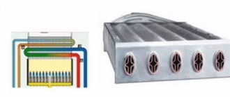
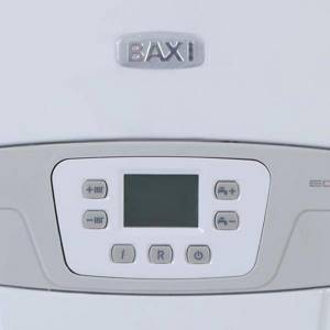
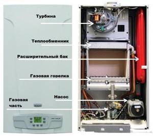
The operating principle of Baxi gas equipment
The combustion chamber is covered with a metal layer of heat-insulating material to contain high temperatures, then a copper heat exchanger is installed on the base of the baxi wall-mounted boiler. A burner is located below, which maintains and controls the flame. When the temperature drops, the system automatically connects the thermostat, which in turn turns on the pump to discharge the pipeline.
As a result, the hot air gradually returns to normal and the baxi wall-mounted boiler begins to work. Initially, the baxi wall-mounted boiler operates at low speed, however, after a few minutes the temperature reaches the required level and the system begins to function at full capacity.
Rice.
3 When there is a sudden change in temperature or drop in pressure, the sensors send a signal to the system, opening the fuel valve to warm up the water. When using a baxi double-circuit gas boiler, you can use two functions simultaneously, or each separately.
Boilers with an open combustion chamber: chimney and air flow
In order for the equipment to work normally and not shut down due to insufficient draft, a vacuum of at least 3 Pa, or better yet 5 Pa, must be created at the boiler output. Therefore, you cannot use a narrowed chimney: its diameter should be slightly larger than the size of the outlet pipe. When designing a chimney, it is necessary that at the boiler outlet there is a vertical section with a height of at least two of its diameters or at least 0.5 meters.
When the pipe is installed on the roof, it must rise above the ridge by at least 0.5 meters. The chimney itself can have no more than three bends at 90o, and the maximum length of the horizontal section is 3 meters. For better draft, you need to provide a slope towards the vertical section of the chimney - 1 cm for each meter of horizontal section. The total height of the chimney from the burner to its top should be 4-5 meters.
If the house is located next to a taller building, it may not be possible to achieve the necessary draft. The problem is solved by the use of turbocharged boilers with a closed combustion chamber.
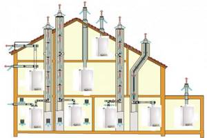
For stable operation of the boiler, a properly constructed chimney is required (click on the picture to enlarge the size)
For normal ignition of boilers with an open combustion chamber, a sufficient amount of oxygen is required. To do this, the room where the boiler is installed must have good ventilation and draft. If there is a lack of air when igniting the boiler, a popping sound is heard. What is needed for good draft is described above, and to supply air, you can arrange for it to be taken from the street with grilles vented in the area where the burner is located.
If it is quite difficult to create an air flow at a sufficient level, it is advisable to use equipment with a closed combustion chamber and forced removal of combustion products - turbocharged boilers.
Grounding
Between grounding and neutral, the potential must be less than 0.5 V. If this requirement is not met, there is a constant potential on the boiler grounding block, which causes a number of malfunctions: malfunctions of the automation, loss of ionization current (burner control), etc. .P. If such a problem exists, it is recommended to install a transformer with galvanic isolation. This allows you to solve problems of insufficiently competent grounding.

If the grounding is incorrect, there is a constant potential on the grounding block, which leads to failures during ignition and frequent shutdowns of the boiler