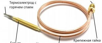
Full technical description of gas valve Eurosit 630
Full technical description of gas valve Eurosit 630
Today, this is the most common gas valve installed on non-volatile gas boilers of Russian and foreign production. Below we provide you with detailed information on this device, which, in our opinion, can be very useful not only for professionals. Information provided by SIT Group.
If you are interested in directly diagnosing the malfunction of AOGV boilers with imported units, we bring to your attention "Faults of AOGV with a Honeywell or Eurosi unit"
So. What is Eurosit 630, essentially? This is a multifunctional gas supply regulator with a modulating thermostat and the function of full modulating activation of the main burner. Eurosit 630 is a non-volatile device, which makes it unique for solving problems of any kind, say, operating a boiler from a gas holder or from liquefied gas cylinders, without the use of electricity sources. The valve is available in various designs and is used without any additional complications in gas convectors, gas boilers, grills and other wide variety of gas-consuming equipment that requires precise temperature control.
Basic technical capabilities
In parentheses we give a function designation that will help in understanding the two working schemes below.
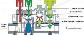
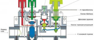
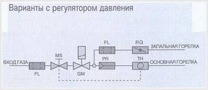
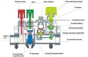
1. Control knob with positions “off”, “ignition”, “temperature”. (MS) 2. Thermoelectric flame protection system (we are talking about a thermocouple) with blocking the gas supply to the main burner after switching off (the blocking is available after switching off the boiler, i.e. it means protection from unauthorized activation, for example children). (GM) 3. Maximum gas flow adjustment device (RQ) or, optionally, a pressure regulator. (PR) 4. Minimum gas flow adjustment screw. (by pass) 5. Modulation thermostat with the function of completely turning off the main burner. (TH) 6. Gas outlet to the pilot burner with a gas flow adjustment screw. (RQ) 7. Inlet filter and pilot burner filter. (FL) 8. Connections for measuring gas pressure. 9. Gas supply, optionally, from the side or from below. 10. Options for gas connections of the multifunction regulator: pipe with external thread or pipe connection using a nut with a seal.
Two variants of operating schemes (with and without pressure regulator)
Technical data of the Eurosit 630 valve (EN 126 standard)
For reference. The EN 126 standard applies to control devices with two or more functions, one of which is gas shut-off.
Connections 1/2 ISO 7 Operating position - any Gas used (families) - 1,2 and 3 Maximum gas input pressure - 50 mbar Regulator setting range from 3 to 18 mbar Operating ambient temperature from 0 to 80C Pressure regulator (optional) - Class. C Torsional and bending stability - Group 2 Thermoelectric protection system (using SIT thermocouples) Ignition time less than 10 sec. Reset time less than 60 sec. Rated glass of ignition cycles - 10,000 Manual reset system: estimated number of reset cycles - 10,000
Characteristics
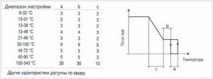
The characteristics of the thermostat with the function of completely turning off the main burner are shown in the following table and graph:
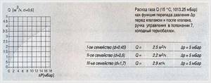
Gas consumption
EXPLOITATION
Ignition of the pilot burner
Make sure the control knob is in the "off" position, turn the control knob to the "spark" position. Press the control knob and light the pilot while holding the control knob for a few seconds. (Fig. 1)
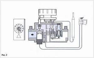
Release the control knob and check that the pilot burner is lit (Fig. 2). If the pilot burner goes out, repeat the ignition procedure. If all other attempts to start the pilot burner have not resulted, either the gas control thermocouple is faulty, or the circuit between the “poor draft” thermal relay and the breaker is broken.
Temperature selection
Turn the control knob to the position corresponding to the selected temperature (Fig. 3)
Duty position
When turning the control knob from the selected temperature position to the “spark” position, the main burner goes out, but the pilot burner remains lit. That is, in essence, this position puts the boiler on, like “a car idling.” Is the boiler working? Yes. Is it warm? No.
IMPORTANT! This mode allows you to cool the boiler when there is a necessary sharp change in the operating temperature of the boiler from higher to lower. Otherwise, without cooling the boiler in this way, you can easily “crush” the modulation thermostat cylinder (in Russian, bellows-thermocylinder assembly (like the Zhukovsky boiler)
Turning off the boiler
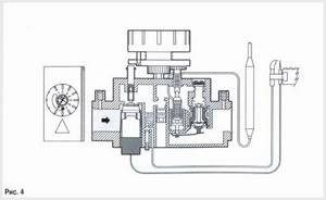
Turn the control knob to the "Off" position. (Fig. 4)
ATTENTION! Restarting the device after an unexpected emergency shutdown can be done approximately a minute after the boiler is turned off. Because turning the knob to the “pilot” position is possible only after the flame control thermocouple has cooled. (i.e. the handle should bounce up rather than remain pressed down). While the thermocouple produces thermoEMF, the thermoelectric flame control device is in the blocking position.
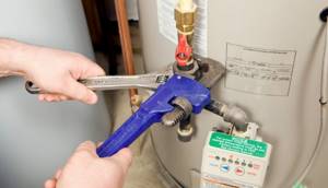
Installation
The gas valve Eurosit 630 complies with current safety standards. Installation on gas consuming equipment must be carried out in accordance with the specific requirements that exist for this equipment.
Firstly , compliance with the requirements regarding thermoelectric protection must be checked. Now we will explain what we are talking about here. Those who have ever seen, this is especially widespread in cases with Economy automation units on domestic gas boilers, where the solenoid valve button, which “bounces” all the time, is tied with tape or secured in a pressed position with whatever you like so that the boiler works. The malfunction here is 90% obvious - the thermocouple is faulty or has poor contact with the solenoid valve. The thermocouple replacement procedure usually takes 2-3 minutes. But for some reason, no. The button is attached, and when the igniter goes out for any reason (and there are any number of them), the flow of gas into the house is always open, as they say, wide open. Secondly. Compliance with gas pressure requirements. Here we are talking about the presence of a pressure reducer. This applies, you understand, to the operation of the valve on liquefied gas, be it a gas tank or cylinders. At first glance, the requirement is simple, but practice sometimes shows something completely different. Moreover, we are talking here not so much about Eurosit 630 gas valves, but about gas valves, for example, Sigma 845.
A small but useful digression
When the specified pressure requirement is not met, do you know what happens? The Sigma 845 gas valve is installed on a huge number of wall-mounted and floor-standing gas boilers. Moreover, the boilers are not cheap, serious, volatile, with control boards, electric ignition, etc. What we have? Usually this is what. The guys came to do the heating. Done. Does the work need to be submitted? Necessary. Boiler, for example, BAXI floor-standing. There is a gas tank, there is a reducer at the output. They twist and turn, but no one understands what the pressure gauge shows at the outlet. It seems like it should be 2750 Pa or about 300 mm water column, but there the scale is three orders of magnitude coarser than necessary. You can't see anything on this one. The boiler either gives a “no gas” error or does not start at all. Or it will work for half an hour, and then that’s it. Who is to blame when there is no gas? Of course, the gas valve! In the end, do you know what they do? They remove the valve from a completely new boiler and start blowing into it from all sides. It's sulking from here, it's not sulking there. The result is complete panic! Buying the most common one with a factory setting of 300 mbar, to the great amazement of everyone, turns out to solve the problem. It is clear that this requirement also applies to Eurosit 630. But it is non-volatile, there is no board, it will not give us any errors, but it will affect the consumption. And the pilot flame. When you see a column of flame 15 centimeters high FROM THE IGNITER, you will understand what we are talking about. It is very important to carefully understand the gas pressure requirement. Now let's move on to the mechanics.
Mechanical connections
General recommendations
Never damage sealing parts! Never loosen the assembly screws! Avoid shocks, falls, hitting the valve, etc. And further. Never remove the labels on the valve! The information that is indicated there is very important for you and me, because what if we find a replacement later? The valves, of course, have differences, but more on that later. This will come next. Remove dust protection caps only during installation. Make sure gas flow is in the direction indicated by the arrow on the regulator body. Take care to ensure that foreign materials do not enter the valve during installation. Packing foam especially likes to get into all the holes. It just sticks to everything! The plant indicates that some versions of Eurosit 630 may be supplied without certain parts. This note, of course, was primarily written for ourselves, but it won’t hurt you to know it either.
So, together we check the availability of the following components according to Fig. A: - minimum gas flow adjustment screw - 3 - maximum gas flow adjustment screw (sometimes called) - 2 If there are no screws, insert the screws into the corresponding holes 14 and 15.
Gas connection
1. Use 3/8" threaded pipe. It is also possible to connect a D12 mm tube using an O-ring and nut. 2. The valve has two holes in the inlet channels 10 and 12 and two holes in the outlet channels 11 and 13. The holes that we are not using must be closed with plugs.
Igniter connection
This is pin 8. A standard igniter with a diameter of D1/4" is usually screwed into this hole. This is the usual standard configuration. But it is also possible to insert tubes with a diameter of D4 mm, D6 mm with cone seals and corresponding nuts. At the end of the work, be sure to check all connections for leaks.
Installation and adjustment parameters. Complete list for professionals
1. Check the inlet and outlet pressure using gas pressure measuring fittings 6 and 7. After measuring the pressure, carefully plug the fittings. 2. Setting the maximum and minimum gas flow is carried out only with a cold thermal cylinder. 3. Setting the maximum gas flow (version without pressure regulator) Fig. A Turn knob 4 to position 7. Fully tighten adjustment screw 2, and then gradually turn it out until the required gas flow is achieved. ATTENTION! Once fully tightened, do not remove the screw more than two full turns. 4. Disabling the maximum gas flow function. Fully tighten adjustment screw 2, and then turn it out two turns and lock it. Disabling can also be done by replacing adjustment screw 2 with a plug. In this case, the plug must be completely screwed in. 5. Setting the maximum gas flow (version with pressure regulator) Fig. A. Turn the control knob to position 7. When turning adjustment screw 2 clockwise, the gas flow increases. 6. Disabling the pressure regulator function. Turn adjustment screw 2 fully clockwise. 7. Setting the minimum gas flow. Slowly turn the control knob clockwise to the minimum power position (as close as possible to the main burner start position). When turning adjustment screw 3 counterclockwise, the gas flow increases. 8. Setting the gas supply to the igniter. When screw 5 is turned clockwise, gas consumption decreases. 9. Disabling the function of setting the gas supply to the igniter. Fully tighten adjustment screw 5, and then turn it out two turns and lock it. 10. Changing the type of gas. Set the gas pressure at the outlet of the reducer or use a ready-made reducer with a factory setting. We remember that flame separation or breakthrough is strictly prohibited at the maximum and minimum gas pressure, respectively.
Repair of gas valve Eurosit 630
The manufacturer allows only one type of repair work - replacement of the magnetic block. This usually happens when the thermocouple is fully operational and the entire circuit from the thermal relay to the breaker is also operational. All other work, and especially work of the “Kulibin + 0.5 ppm” or “who knows what” class, is strictly prohibited.
Now about the difference between Eurosit 630 blocks. How do they usually differ from each other?
The blocks differ mainly only in the range of temperature control. Standard operating mode for gas boilers is from 40C-90C. Although, on boilers with a power of 11.6 kW there were valves with a temperature range from 40C to 72C. This does not affect the operation of the boilers in any way, therefore, valve 0630068, which supports the range 40C-90C, practically solves any problem.
To quickly assess the situation, we provide a list of temperature conditions that can be indicated on the label of your unit. Attention. Not to be confused with ambient temperature! Such data is also on the block label. Be careful!
Operating temperature range of the Eurosit 630 gas valve: Link to the complete catalog of all Eurosit 630 valves on our website.
The dimensions and thread data of the Eurosit 630 block are given below
Main types and advantages of automatic devices for gas heating boilers
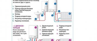
Today there are two types of automatic devices for heating boilers: volatile and non-volatile. Which of the two groups of automatic controls for a gas boiler is better, we will consider in detail.
…
Non-volatile
This group includes mechanical devices for controlling work processes inside the boiler. Advantages of this group:
- these devices have a lower price;
- manual adjustment is not difficult to operate the device;
- The device units are completely autonomous and do not depend on electricity.
The principle of manual adjustment: the arrow on the temperature scale sensor is set to the desired temperature. After turning on the boiler in operating mode, the thermostat controls the set temperature. A thermocouple, which is a transducer that measures operating temperature, is two metal rods (an alloy of iron and nickel) that respond to changes in temperature. Depending on the temperature value, the rod either decreases or increases. Since the rod is connected to the valve, the valve, under the influence of the rod, accordingly increases or decreases the fuel supply to the burner.
Two sensors have been added to modern mechanical automation units: thrust and flame.
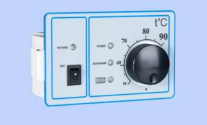
Electronic devices
A volatile device is an electronic device that regulates the gas supply using a tap. What are the functions of this type of automation for a gas boiler:
- close and open the gas supply valve;
- set automatic boiler mode;
- monitor the operation of the burner using a temperature sensor;
- in case of an unusual situation or a programmed shutdown, stop the boiler operation;
- visually demonstrate the operation of the boiler, water temperature, etc.
In the most modern electronic devices, the functions have been expanded, adding:
…
- control and monitoring of pump operation;
- protection of the heating system from low temperatures;
- protection of the heating system in case of valve failure;
- independent diagnostics and identification of defects in individual elements of the device.
Thanks to this innovation, there is a guarantee of uninterrupted operation of the boiler in compliance with conditions and temperatures. And the fault diagnosis system will help keep the device working much longer, because it is easier to prevent than to make major repairs. These are compelling arguments when asking: which automation is better for gas boilers.
To prevent any problems during a power outage or power surges, you can protect yourself by installing a stabilizer and an uninterruptible power supply.
Automatic 630 EUROSIT. Adjustment.
Today, the Rostov Boiler Equipment Plant CJSC Rostovgazoapparat produces Siberia boilers, widely known in our country. The author of these lines had the honor of installing such a boiler in his own home. Everything would be fine, but in severe frosts problems with the insufficient power of this device began to appear. At first, I was guilty of power, since the area of the heated house is 95 square meters. m. and the declared boiler power is 11.6 kW. Naturally, the power reserve is small, since the recommended reserve should be + 30% of the area of the house. My boiler must be at least 12.5 kW. that is, for heating 125 sq.m. Now a brief background for buyers of Siberia boilers.
WARNING
Some versions of the multifunction gas regulator are supplied without certain parts.
Therefore, when installing regulators, it is necessary to check the presence of the following components: • minimum gas flow adjustment screw 3
(
Fig. A
) • maximum gas flow adjustment screw
2
(
Fig. A
) or, optionally, pressure regulator
2'
(
Fig. A*
) If not, perform installation as follows: • check that the accessory code is correct • insert the minimum gas flow adjustment screw into hole
14
(
Fig. B
), the maximum gas flow adjustment screw or pressure regulator into hole
15
(
Fig. B
) • insert the accessories and wrap completely.
Tightening torques: - adjustment screws 7Nm - pressure regulator: 1Nm Gas connection
Use a gas pipe with Rp 3/8 ISO 7 thread. Tightening torque: 25 Nm.
It is possible to connect a tube diameter of 12 mm using an o-ring and a nut (codes 0.958.025 and 0.957.007). Tightening torque 15 Nm. The valve has two inlet ports 10
and
12
(
Figure D
) and two outlet ports
11
and
13
(
Figure D
).
Holes that have not been used must be closed with plugs (code 0.972.058). Tightening torque 7 Nm. Connecting the pilot burner
pin
8
(
Fig. D
) Tubes with diameters of 4 mm, 6 mm or 1/4? can be used.
Use nuts and o-rings of the appropriate size. Tightening torque 7 Nm. ATTENTION
After completing the work, check the connections for leaks.
Setting the maximum and minimum gas flow
These settings are made with a cold bulb.
Setting the maximum gas flow
(version without pressure regulator) - (
Fig. A
).
Turn control knob 4
to position
7
.
Fully tighten the adjustment screw 2
, and then gradually turn it out until the required gas flow is achieved.
WARNING
Once fully tightened, do not back out the screw more than
two
turns.
Disabling the maximum gas flow function
Fully tighten the adjustment screw
2
, and then turn it out two turns and lock it.
Disabling can also be done by replacing adjustment screw 2
with a plug (code 0.972.057). In this case, the plug must be completely screwed in.
Setting the maximum gas flow
(version with pressure regulator) - (
fig. A*
).
Turn the control knob to position 7
.
When turning the adjustment screw 2' clockwise (VERSION WITH PRESSURE REGULATOR)
, the gas flow increases.
Disabling the pressure regulator function
2'
adjustment screw fully clockwise.
Setting the minimum gas flow
Slowly turn the control knob clockwise to the minimum power position (close to the main burner off position).
When turning adjustment screw 3
counterclockwise, the gas flow increases. It is also possible to use screws with calibrated holes (optional) instead of screws for adjusting the maximum and minimum gas flow. In this case, the screws must be tightened with a tightening torque of 7 Nm.
Setting the gas supply to the pilot burner
When screw
5
clockwise, gas consumption decreases.
ATTENTION
After completing all adjustments and adjustments, check the tightness of the seals and the correct operation of the equipment. Flame separation or breakthrough is strictly prohibited at the corresponding maximum and minimum gas pressure. After completing the adjustment work, secure the seals and/or adjustment screws with paint.
I present questions and answers from the old site; if you don’t find anything useful for yourself, write below in the comments.
Main characteristics and operating principle of the SABC system
SABC gas boiler safety automation is a system designed to ensure safe, efficient and economical operation of the equipment. The system is pneumatic and does not depend on the electrical network; it is installed on non-volatile structures. It is noteworthy that the system can work not only on gas boilers, but also on devices operating on solid fuel and combination boilers.
The operation of the gas automation safety system is based on sensor indicators: coolant temperature, firebox; presence of traction; gas pressure. The system takes into account any change in values, their deviation from the norm.
SABC automation consists of the following elements:
- gas pressure regulator;
- sensors: draft, combustion, temperature, pressure, thermocouple, pressure gauge, etc.;
- fuel supply blocking element;
- gas burner design;
- a control unit that controls and directs the operation of the heating system.
To understand the principle of operation, it is necessary at the same time to briefly familiarize yourself with the main details of the system. So, on the control unit there is a handle, when turned, the lever mechanism exerts pressure on the gas valve. As a result of turning on the gas valve, the burner starts. Afterwards, the system sensors are activated, taking readings of temperature, thrust and other operating values.
Each sensor immediately reacts to changes and deviations from the norm in its indicators. For example, a draft sensor is a plate that, when the draft indicators decrease and, accordingly, the temperature in the chamber increases, deforms and puts pressure on the valve that closes the gas supply. The temperature sensor works in the same way. As you can see, automation of boilers makes it possible not to monitor the operation of devices hourly, relying on the autonomous operation of the system.
All work on connection, configuration and preventive inspection is carried out only by a specialist with the appropriate qualifications.
Features of operation of automation in gas heating boilers
For safe use and long service life, it is necessary to follow a number of rules when using gas heating appliances. Before turning on the device, carefully read the user manual; gas is not to be trifled with.
All work on installation, connection, settings, including firmware of the control unit must be performed by specialists licensed for such activities. Regular inspections of the device by a technician, diagnostics of the microprocessor of the control unit, and viewing of reports from the device’s memory module are required.
Inspect for defects or wear of individual parts. It is extremely rare to completely change the automation; all parts can be changed as they wear out. If serious damage is detected, repairs should be carried out. During this period, heating appliances should not be used.
Fan control
Let's consider the principle of fan control in automatic and manual modes. In the first case, the temperature controller automatically selects the fan rotation speed according to the type of fuel selected in the program and the temperature sensor readings. The fan speed can be changed from 0% to 100% in 10% increments. When the set boiler temperature is reached, the programmer maintains it by smoothly adjusting the fan power. And when the temperature exceeds the set value by 5 °C, the fan turns off completely. If the temperature of the outlet coolant drops below a preset value, the programmer turns on the fan and then smoothly regulates its power, preventing the temperature from lowering. Thus, stability of the set coolant temperature is achieved.
Using the programmer, you can set the type of fuel used - this helps to use fuel more efficiently. When heating with wood, wood briquettes, pellets, you must select the “Firewood” function; peat briquettes, brown or hard coal – “Coal”; “Shtyb” – selected when firing with anthracite (fine coal). The specifics of the programmer's operation in manual mode are shown in the graph in Fig. 2. A fan with a constant power in the range from 0 to 100% forces air into the combustion chamber. The required power can be set in 10% increments in the programmer menu. The automation turns off the fan when the set temperature is reached. When the temperature in the boiler drops below the set hysteresis value, the fan automatically turns on. In this mode, the automation is programmed to periodically “blow through” the boiler. In the controller menu you can set the duration and frequency of this function. It is also useful when connecting non-standard heating systems.
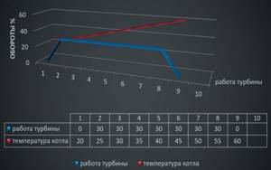
Rice. 2. Fan operation schedule in manual mode
In manual mode, the boiler is extinguished by turning off the fan when the temperature drops below the set value, since the programmer determines this as complete burnout of the fuel and further operation of the fan is impractical.
Connecting the chronothermostat
A special case of using automation in the form of a normally open contact thermostat is the use of a chronothermostat. On the thermostat itself, time periods are set and two or three heating levels are set: the lowering temperature is “night” and the temperature is “day”. But in any case, the coolant temperature will be the one set from the control panel.
+ The boiler heating differential is set based on the user's needs.
— The temperature set from the control panel is adjusted manually.