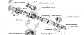
Calculation of ventilation ducts is one of the stages of ventilation calculation and consists of determining the size of the air duct depending on the air flow that must pass through the duct in question. In addition, problems arise in determining the surface area of the air duct. Let's look at them in more detail.
To calculate air ducts, we recommend using the online calculator located above. The initial data for the calculation are air flow and the maximum permissible air speed in the air duct.
The advantage of our calculator is that as a result of the calculation you will find out not only the recommended cross-section of round and/or rectangular air ducts, but also the actual air speed in them, equivalent diameter and pressure loss per 1 meter of length.
Read about calculating the area of air ducts in a separate article.
Algorithm for calculating the cross-section of air ducts
Calculation of the cross-section of air ducts involves determining the size of the air ducts depending on the flow rate of the air passed through. It is performed in 4 stages:
- Conversion of air flow to m3/s
- Choosing air speed in the duct
- Determining the cross-sectional area of the duct
- Determining the diameter of a round or width and height of a rectangular duct.
At the first stage of air duct calculation, the air flow rate G, usually expressed in m3/hour, is converted to m3/s. To do this, you need to divide it by 3600:
- G [m3/s] = G [m3/hour] / 3600
At the second stage, you should set the speed of air movement in the duct. The speed should be specified, not calculated. That is, choose the air speed that seems optimal.
The high air velocity in the duct allows the use of small cross-section ducts. However, the air flow will be noisy, and the aerodynamic resistance of the air duct will greatly increase.
Low air speed in the air duct ensures quiet operation of the ventilation system and low aerodynamic resistance, but makes the air ducts very bulky.
For general ventilation systems, the optimal air speed in the air duct is considered to be 4 m/s. For large air ducts (600x600 mm or more), the air speed can be increased to 6 m/s. In smoke removal systems, air speed can reach or exceed 10 m/s.
So, at the second stage of calculating air ducts, the air speed v [m/s] is set.
At the third stage, the required cross-sectional area of the air duct is determined by dividing the air flow by its speed:
- S [m2] = G [m3/s] / v [m/s]
At the fourth , final stage, its diameter or the lengths of the sides of a rectangular section are selected for the resulting cross-sectional area of the air duct.
General information
Aerodynamic calculation is a technique for determining the cross-sectional dimensions of air ducts to level out pressure losses, maintain the speed of movement and the design volume of pumped air.
With the natural ventilation method, the required pressure is given initially, but the cross-section must be determined. This is due to the action of gravitational forces, which encourage air masses to be drawn into the room from the ventilation shafts. With the mechanical method, a fan operates, and it is necessary to calculate the gas pressure, as well as the cross-sectional area of the box. Maximum speeds inside the ventilation duct are used.
To simplify the technique, air masses are taken as a liquid with zero percent compression. In practice, this is true, since in most systems the pressure is minimal. It is formed only from local resistance, when it collides with the walls of the air ducts, as well as at places where the area changes. This was confirmed by numerous experiments conducted according to the methodology described in GOST 12.3.018-79 “System of Occupational Safety Standards (OSSS). Ventilation systems. Methods of aerodynamic tests".
The technique involves selecting the area and cross-sectional shape for each section of the ventilation system. If we take it as a whole, then the definition of losses will be conditional, not corresponding to the real picture. In addition to the movement itself, the injection is also calculated.
Calculations of air ducts for ventilation, based on aerodynamics, are carried out with a varying number of known data. In one case, the calculation starts from scratch, and in the other, more than half of the initial parameters are already known.
Example of air duct calculation
As an example, let's calculate the cross-section of an air duct with an air flow of 1000 m3/hour:
- G = 1000/3600 = 0.28 m3/s
- v = 4 m/s
- S = 0.28 / 4 = 0.07 m2
- In the case of a round duct, its diameter would be D = root (4·S/ π) ≈ 0.3 m = 300 mm. The nearest standard duct diameter is 315 mm.
In the case of a rectangular duct, it is necessary to select A and B such that their product is approximately 0.07. It is recommended that A and B do not differ from each other by more than three times, that is, a 700x100 air duct is not the best option. Better options: 300x250, 350x200.
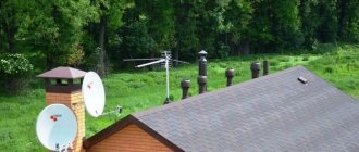
Features of determining the length of ventilation pipes
Another important parameter when designing ventilation systems is the length of the outer pipe. It unites all the channels in the house through which air circulates and serves to remove it outside.
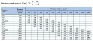
Calculation according to the table
The height of the ventilation pipe depends on its diameter and is determined from the table. Its cells indicate the cross-section of the air ducts, and the column on the left shows the width of the pipes. Their height is indicated in the top line and is indicated in mm.
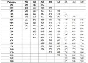
Selecting the height of the ventilation pipe according to the table
In this case, you need to take into account:
- If the ventilation pipe is located next to the chimney, then their heights must match to avoid smoke penetration into the premises during the heating season.
- When the air duct is located from the ridge or parapet at a distance that does not exceed 1.5 m, its height must be more than 0.5 m. If the pipe is located within 1.5 to 3 m from the roof ridge, then it cannot be lower his.
- The height of the ventilation pipe above a flat roof cannot be less than 0.5 m.
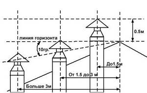
Location of ventilation pipes relative to the roof ridge
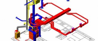
Using the Software
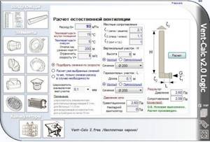
An example of calculating natural ventilation using special programs
Calculating natural ventilation is less labor-intensive if you use a special program for this. To do this, first determine the optimal volume of air flow, depending on the purpose of the room. Then, based on the data obtained and the features of the designed system, a calculation of the ventilation pipe is made. In this case, the program allows you to take into account:
- average temperature inside and outside;
- geometric shape of air ducts;
- roughness of the internal surface, which depends on the material of the pipes;
- resistance to air movement.
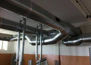
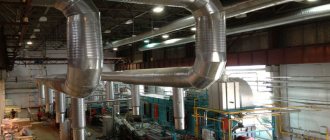
Ventilation system with round pipes
As a result, the required dimensions of ventilation pipes are obtained for the construction of an engineering system that must ensure air circulation under certain conditions.
Correct calculation of the parameters of ventilation pipes will allow you to design and build an effective system that will make it possible to control the level of humidity in the premises and provide comfortable living conditions.
Source
Calculation of equivalent diameter of air ducts
The equivalent diameter of a rectangular duct is calculated by the formula:
- Deq_pr = 2 A B / (A + B), where A and B are the width and height of the rectangular air duct.
For example, the equivalent diameter of a 500×300 duct is 2·500·300 / (500+300) = 375 mm. This means that a 375mm round duct will have the same aerodynamic drag as a 500x300mm rectangular duct.
The equivalent diameter of a square duct is equal to the side of the square:
- Deq_q = 2 A A / (A+A) = A.
And this fact is very interesting, because usually the larger the cross-sectional area of the air duct, the lower its resistance. However, the round shape of the air duct section has the best aerodynamic performance. That is why the resistance of square and round ducts are equal, although the cross-sectional area of a square duct is 27% larger than the cross-sectional area of a round duct.
In general, the formula for the equivalent duct diameter is as follows:
- Deq = 4·S / P, where S and P are the area and perimeter of the air duct, respectively.
Using this formula, you can confirm the correctness of the above formulas for rectangular and square ducts, and also ensure that the equivalent diameter of a round duct is equal to the diameter of this duct:
- Dround = 4·π·R2 / 2·π·R = 2R = D.
In addition, a table of equivalent duct diameters
Features of aerodynamic calculations
Axonometry
Aerodynamics calculations are performed strictly when the required volumes of air masses are calculated. This is the basic rule. The installation points of air ducts and deflectors are also determined in advance.
The graphical part for calculating aerodynamics is an axonometric diagram. It indicates all devices and the length of sections. Then the overall network is divided into segments with similar characteristics. Each section of the network is calculated separately for aerodynamic resistance. After determining the parameters in all areas, they are transferred to the axonometric diagram. When all the data is entered, the main air duct line is calculated.
Related Posts
- Calculation of the area of air ducts and fittings, aerodynamic and other indicators
- Pros and cons of air distribution from the floor
- How to attach air ducts to the wall yourself
- Features and procedure for calculating exhaust and supply ventilation
- Soundproofing ventilation: device features and installation methods
- Air exchange in residential premises: what you need to know for a comfortable life
- Calculation of general and local ventilation of production premises
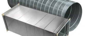
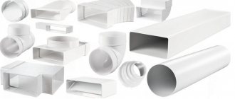
- Dimensions and types of plastic air ducts for ventilation
- DIY cellar ventilation in the garage
- Ventilation shaft in a multi-storey building
- Ventilation grille with non-return valve
- Installing ventilation in a private house with your own hands: step-by-step instructions
- Features and installation of galvanized air ducts for ventilation
- What should be the diameter and length of the exhaust duct?
- Breathe easily or ventilation systems of a frame house
- Plastic ventilation pipes for hoods: types, their characteristics, application
- Why does the hood blow in the opposite direction in an apartment?
- Air handling units with built-in cooling
- Ventilation laboratory
- Types of ventilation in the bath
- Ventilation in a suspended ceiling
- Subtleties of crimping a heating system
- Online calculation of the capacity of round and rectangular profile pipes
- How to calculate the cross-sectional area of a pipe
- Features and arrangement of chicken coop ventilation
Read with this
- Calculation of the area of air ducts and fittings, aerodynamic and other indicators
- Pros and cons of air distribution from the floor
- How to attach air ducts to the wall yourself
- Features and procedure for calculating exhaust and supply ventilation
- Soundproofing ventilation: device features and installation methods
- Air exchange in residential premises: what you need to know for a comfortable life
- Calculation of general and local ventilation of production premises
- Dimensions and types of plastic air ducts for ventilation
- DIY cellar ventilation in the garage
- Ventilation shaft in a multi-storey building
Calculation of the ventilation system
Tables and formulas for calculating ventilation.
This material was kindly provided by my friend Spirit.
According to sanitary standards, the ventilation system must ensure that the air in the room is replaced in one hour, this means that in one hour a volume of air equal to the volume of the room must enter and be removed from the room. Therefore, the first step is to calculate this volume by multiplying the area of the room by the height of the ceilings. If you have a room with an area of 40 m2 with a ceiling height of 2.5 m, then its volume will be 40 * 2.5 = 100 m3. This means that the capacity of the supply and exhaust systems should be 100 m3/h. This is the minimum consumption, I recommend twice as much. You are looking for a fan with this performance, or better yet even more, because the performance is indicated on the condition that there is no back pressure, and when you put a filter in the supply system, back pressure will appear and reduce the performance. If you have a capacity of 200 m3/h, then in a 125mm pipe the approximate flow velocity will be 4.5 m/s, in a 100mm pipe - 6.5 m/s, and in a 160mm pipe - slightly less than 3 m/s. It is believed that comfortable air speed for humans is up to 2 m/s. If you have an anemometer, then knowing these numbers you can check the performance of the ventilation system.
Next, let’s say you want to install a heater in the supply duct. Using the fourth table you can determine its power. Let’s say it’s -10°C outside, but you want it to be +20°C in the room, which means the temperature difference is 30°C. We find the line 200 m3/h, look at the intersection of the 30°C column, and get a power of 2010 W. It is clear that this is in the absence of other heat sources, so in reality significantly less will be required.
The next point is the calculation of humidity. Warm air holds more water than cold air. Therefore, when heated, its humidity decreases, and when cooled, it increases. Let’s say it’s -10°C outside with 80% humidity, and the air in the room heats up to +20°C. The water content in one cubic meter is 2.1*0.8=1.68 g/m3, and the humidity of the heated air will be 1.68/17.3=0.097, that is, approximately 10%. How much water must be evaporated to obtain a humidity of, say, 50% at a flow rate of 200 m3/h?
Answer: 200*(17.3*0.5-1.68)=1394 g/h=1.4 kg/h
Source