Washing machine Hotpoint-Ariston VMSL 501 B, white
15699 ₽ More details
Washing machine Candy CS34 1052DB1/2-07, white
16099 ₽ More details
Built-in washing machines
Air ducts of supply or exhaust ventilation systems can be made of different materials and have different configurations. Moreover, their overall dimensions depend entirely on two other parameters, and the formula for calculating air speed reflects this dependence well. These two parameters are the air flow rate moving through the channel and the speed of its movement.
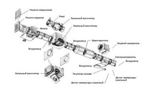
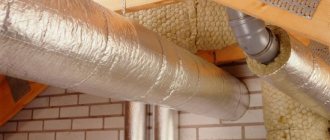
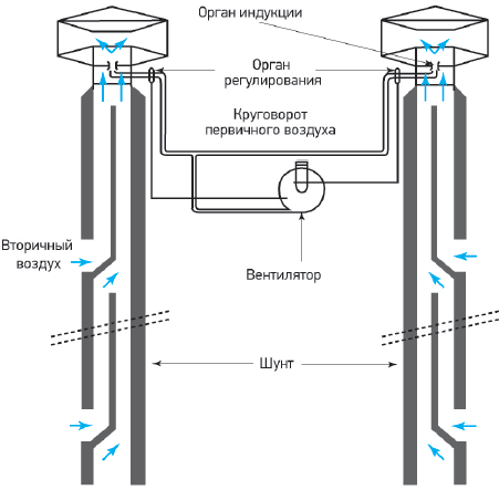
Air duct arrangement diagram.
Definition of natural ventilation
With natural ventilation, air enters through supply valves or cracks in wooden windows.
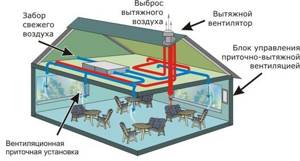
Ventilation is responsible for comfortable conditions in a private and multi-storey house. In the multi-apartment sector, ventilation risers and shafts are provided that remove exhaust air outside the building (to the roof). To normalize the microclimate, the removal and influx of fresh air masses is required.
In apartments with old wooden frames, air enters the living area through loosely closed doors. Modern requirements for interior decoration are tightening sealing measures, and metal-plastic fillings of openings with double-glazed windows are characterized by the absence of cracks. Unpleasant odors from the bathroom and kitchen are removed through the shaft, but inside the apartment there is an area of rarefaction in which the residents feel uncomfortable.
Variety of ventilation systems
Currently, the construction industry offers a wide range of ventilation systems designed for any area and purpose of premises. Their main classification is the division into supply and exhaust types. In the first case, air enters the room through air ducts, where its pressure increases. As a result of this process, the air escapes outside through doors, windows and other openings that are located in the room.
The supply system has a complicated mechanism: before the air enters the room, it passes through the air intake grille and valve and ends up in the filter element. After it it is sent to the heater, and then to the fan. And only after this stage it reaches the finish line. This type of ventilation system is suitable for rooms with a small area.
A combined version of supply and exhaust systems is considered the most effective method of ventilation. This is due to the fact that polluted air does not stay in the room for a long time, and at the same time fresh air constantly enters. It is worth noting that the diameter of the air duct and its thickness directly depend on the desired type of ventilation system, as well as the choice of its design (regular or flexible).
Based on the way air masses move in a room, experts distinguish between natural and mechanical ventilation systems. If the building does not use mechanical equipment to supply and purify air, then this type is called natural. In this case, there are often no air ducts. The best option is a mechanical ventilation system, especially when there is no wind outside. This system allows air to move in and out of the room through the use of various fans and filters. Also, using the remote control, you can set comfortable temperature and pressure levels inside the room.
In addition to the above classifications, there are general and local ventilation systems. In production, where it is not possible to remove air from sources of pollution, general ventilation is used. In this way, harmful air masses are constantly replaced by clean ones. If polluted air can be eliminated near the source of its origin, then local ventilation is used, which is most often used in domestic living conditions.
Proper organization and standards
Natural ventilation has different effectiveness in winter and summer. The temperature difference between the outgoing and incoming masses causes an acceleration of the inflow, which is typical for cold times. In summer, the temperature outside the window is higher than room values, and the air speed in natural ventilation slows down. The work of air exhaust shafts becomes less efficient.
Regulatory acts and conditions for calculating systems are set out in the document SNiP 41.01 - 2003 “Heating, air conditioning and ventilation”. Requirements for the operation of natural air ducts are also contained in SP 73.13320 - 2012 “Internal sanitary systems of buildings”. Organizing the inlet flow means using special valves in the window frames and walls of the building to optimize air exchange.
Some economic aspects of air duct sizing
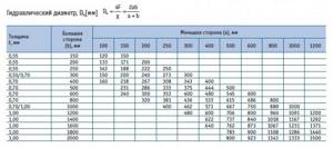
Table for calculating the hydraulic diameter of the duct.
When calculating the size and speed of air in the air duct, the following dependence is observed: as the latter increases, the diameters of the channels decrease. This has its advantages:
- It is much easier to lay smaller pipelines, especially if they need to be suspended at a great height or if the installation conditions are very cramped.
- The cost of channels of smaller diameter is also correspondingly less.
- In large and complex systems that extend throughout the building, additional equipment (butterfly valves, check valves and fire dampers) must be installed directly into the ducts. The sizes and diameters of this equipment will also decrease and their cost will decrease.
- The passage of pipelines in an industrial building can become a real problem if its diameter is large. Smaller sizes will allow you to pass as needed.
The main disadvantage of this choice is the high power of the ventilation unit. High air speed in a small volume creates high dynamic pressure, the resistance of the system increases, and its operation requires a high-pressure fan with a powerful electric motor, which causes increased electrical energy consumption and, accordingly, high operating costs.
Another way is to reduce the speed of air flow in the air ducts. Then the parameters of the ventilation unit become economically acceptable, but many installation difficulties arise and the high cost of materials arises.
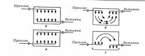
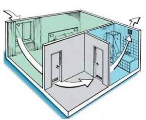
Scheme of organizing air exchange during general ventilation.
The problem of a large pipe passing places overloaded with equipment and utility networks is solved by many turns and transitions to other types of sections (from round to rectangular or flat-oval). The cost problem has to be solved once.
During Soviet times, designers, as a rule, tried to find a compromise between these two solutions. Currently, with rising energy prices, there is a tendency to use the second option. Owners prefer to solve financial issues one-time and install more economical ventilation, rather than pay high energy costs for many years. A universal option is also used, in which in main air ducts with high flow rates the flow speed is increased to 12-15 m/s in order to reduce their diameters. Further along the system, a speed of 5-6 m/s is maintained on the branches, as a result of which the pressure losses are equalized. The conclusion here is clear: the speed of air flow in the channels plays an important role for the economy of the enterprise.
Features and application of natural ventilation
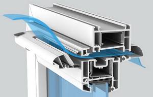
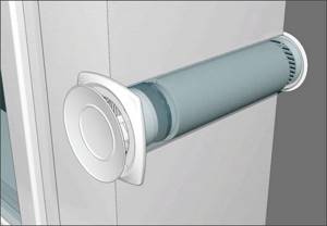
In a room with metal-plastic windows, supply valves are installed on them.
The air in unorganized air ducts is removed using drafts in the channels, usually located in the bathroom, toilet and kitchen. Gravity occurs in proportion to the temperature difference between the external and internal atmosphere and the height of the riser from the ventilation grille to the head of the pipe on the roof.
Through artificial channels and valves are used when there is insufficient draft in ventilation shafts:
- the ventilator is placed in an external wall or frame, the device increases the volume of air, but its operation also depends on the climate;
- the breather simultaneously cleans and ventilates the incoming air using one or a set of filters and membranes, and is mounted in the wall of the house;
- forced circulation refers to the installation of fans in a window or wall niche.
Windy weather plays a role. If you open the transom in the summer, the jet under pressure will squeeze the air into the exhaust shaft. Wind load can be used to operate deflectors, which are installed on the head and improve traction by turning. Natural ventilation remains the cheapest method of ventilation and does not require installation or operation costs.
Parameter values in various types of air channels
Modern ventilation systems use installations that include the entire complex for supplying and processing air: cleaning, heating, cooling, humidification, sound absorption. These units are called central air conditioners. The flow rate inside it is regulated by the manufacturer. The fact is that all elements for processing air masses must operate in optimal mode to ensure the required air parameters. Therefore, manufacturers manufacture installation housings of certain sizes for a given range of air flow rates at which all equipment will operate efficiently. Typically, the flow velocity inside a central air conditioner is in the range of 1.5-3 m/s.
Main and branch channels
Main air duct diagram.
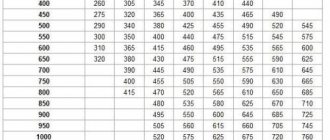
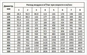
Next comes the turn of the main main air duct. It is often long and transits through several rooms before it begins to branch out. The recommended maximum speed of 8 m/s in such channels may not be observed, since laying conditions (especially through ceilings) can significantly limit the space for its installation. For example, at a flow rate of 35,000 m³/h, which is not uncommon in enterprises, and a speed of 8 m/s, the pipe diameter will be 1.25 m, and if it is increased to 13 m/s, the size will become 1000 mm. Such an increase is technically feasible, since modern air ducts made of galvanized steel, manufactured by the spiral-wound method, have high rigidity and density. This eliminates their vibration at high speeds. The noise level from such work is quite low, and against the background sound from operating equipment it can be practically inaudible. Table 2 shows some popular diameters of main air ducts and their throughput at different speeds of air mass movement.
table 2
| Flow, m3/h | Ø400 mm | Ø450 mm | Ø500 mm | Ø560 mm | Ø630 mm | Ø710 mm | Ø800 mm | Ø900 mm | Ø1 m |
| ϑ = 8 m/s | 3617 | 4576 | 5650 | 7087 | 8971 | 11393 | 14469 | 18311 | 22608 |
| ϑ = 9 m/s | 4069 | 5148 | 6357 | 7974 | 10093 | 12877 | 16278 | 20600 | 25434 |
| ϑ = 10 m/s | 4521 | 5720 | 7063 | 8859 | 11214 | 14241 | 18086 | 22888 | 28260 |
| ϑ = 11 m/s | 4974 | 6292 | 7769 | 9745 | 12335 | 15666 | 19895 | 25177 | 31086 |
| ϑ = 12 m/s | 5426 | 6864 | 8476 | 10631 | 13457 | 17090 | 21704 | 27466 | 33912 |
| ϑ = 13 m/s | 5878 | 7436 | 9182 | 11517 | 14578 | 18514 | 23512 | 29755 | 36738 |
Scheme of an ejection ventilation system.
Side branches of air ducts distribute the supply or exhaust of the air mixture to individual rooms. As a rule, a diaphragm or throttle is installed on each of them - a valve to regulate the amount of air. These elements have considerable local resistance, so maintaining a high speed is impractical. However, its value may also be outside the recommended range, so Table 3 shows the throughput of air ducts of the most popular diameters for branches at various speeds.
Table 3
| Flow, m3/h | Ø140 mm | Ø160 mm | Ø180 mm | Ø200 mm | Ø225 mm | Ø250 mm | Ø280 mm | Ø315 mm | Ø355 mm |
| ϑ = 4 m/s | 220 | 288 | 366 | 452 | 572 | 705 | 885 | 1120 | 1424 |
| ϑ = 4.5 m/s | 248 | 323 | 411 | 508 | 643 | 793 | 994 | 1260 | 1601 |
| ϑ = 5 m/s | 275 | 360 | 457 | 565 | 714 | 882 | 1107 | 1400 | 1780 |
| ϑ = 5.5 m/s | 302 | 395 | 503 | 621 | 786 | 968 | 1215 | 1540 | 1957 |
| ϑ = 6 m/s | 330 | 432 | 548 | 678 | 857 | 1058 | 1328 | 1680 | 2136 |
| ϑ = 7 m/s | 385 | 504 | 640 | 791 | 1000 | 1235 | 1550 | 1960 | 2492 |
Not far from the point of connection to the main line, a hatch is installed in the channel; it is needed to measure the flow rate after installation and adjustment of the entire ventilation system.
Indoor channels
Ventilation air exchange rate.
Distribution channels connect the main branch to devices for supplying or extracting air from the room: grilles, distribution or suction panels, diffusers and other distribution elements. The speeds in these branches can be maintained as in the main branch, if the power of the ventilation unit allows this, or they can be reduced to the recommended ones. In Table 4 you can see the air flow rates at various speeds and channel diameters.
Table 4
| Flow, m3/h | Ø100 mm | Ø112 mm | Ø125 mm | Ø140 mm | Ø160 mm | Ø180 mm | Ø200 mm | Ø225 mm |
| ϑ = 1.5 m/s | 42,4 | 50,7 | 65,8 | 82,6 | 108 | 137 | 169 | 214 |
| ϑ = 2 m/s | 56,5 | 67,7 | 87,8 | 110 | 144 | 183 | 226 | 286 |
| ϑ = 2.5 m/s | 70,6 | 84,6 | 110 | 137 | 180 | 228 | 282 | 357 |
| ϑ = 3 m/s | 84,8 | 101 | 132 | 165 | 216 | 274 | 339 | 429 |
| ϑ = 3.5 m/s | 99,9 | 118 | 153 | 192 | 251 | 320 | 395 | 500 |
| ϑ = 4 m/s | 113 | 135 | 175 | see Table 3 | ||||
The speeds recommended for exhaust and supply grilles, as well as other air distribution devices, must be observed.
The air coming out of them or when being sucked in encounters many small obstacles and produces noise, the level of which must not be exceeded. The sound of the flow coming out of the grate at high speed will definitely be heard. Another unpleasant point: a strong air jet hitting people can lead to illness.
Ventilation systems with natural impulse are usually used in residential and public buildings or in administrative buildings of industrial enterprises. These are various types of exhaust shafts located in the internal partitions of rooms, or external vertical air ducts. The speed of the air flow in them is low, rarely reaching 2-3 m/s in cases where the shaft has a significant height and good traction occurs. When it comes to low flow rates (about 100-200 m³/h), there is no better solution than natural exhaust. Previously and to this day, roof deflectors that operate due to wind load are used in industrial premises. The air speed in such exhaust devices depends on the strength of the wind flow and reaches 1-1.5 m/s.
Calculation and formulas
For natural ventilation, the size of the valve and its capacity are important.
Calculations for a ventilation system involve determining the optimal conditions under which air enters and exits most efficiently.
Calculation of room ventilation includes sections:
- determination of flow speed;
- calculation of air volume;
- calculation of the parameters of the inlet or channel.
When calculating, the frequency of air exchange according to the standards is taken into account, hygienic and sanitary standards, and the area of the room are taken into account. There are technical calculations that calculate the renewal of the microclimate, heat removal, changes in humidity, and the degree of pollution.
Air speed calculation
You can increase the speed of air outflow using a deflector.
The parameter is defined as the speed of flow at each point, and the value does not depend on the direction. Some rooms have uneven air movement, which leads to loss of body heat. The average value of the air speed is taken, which is selected between lower and higher cooling efficiency.
The calculation of the ventilation system in terms of air speed is based on the exchange rate and is found using the formula B = M / 3600 S, where:
- B—speed of moving masses (m/s);
- M—air consumption rate (m3/h);
- S is the cross-sectional area of the air duct (m2).
Consumption is determined at the rate of 60 m3/hour per person if he is continuously in the room and 20 m3/hour if his stay is considered temporary. Such standards are prescribed in sanitary and hygienic rules.
Air volume calculation
The atmosphere is purified due to air exchange in the room. The air mass must be changed several times per hour so that the level of pollution is within acceptable limits. The number of replacements is called the air exchange rate, on the basis of which the flow rate is determined.
The multiplicity index can be calculated using the formula N = V / Y, where:
- N — frequency of air replacement (times/hour);
- V is the amount of air replenishing the room per hour (m3/h);
- Y is the volume of the required room (m3).
The indicator is given in special tables so as not to calculate it for rooms of the same size and functionality.
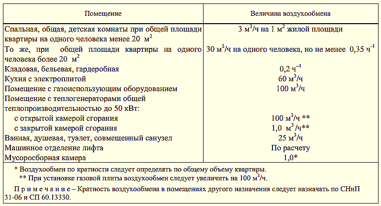
Recommended multiplicity:
- residential premises - 3 m3/h for 1 square area;
- kitchen – 6 – 8 m3/h;
- bath, shower, laundry - 7 - 9 m3/h;
- wardrobe, pantry - 1 - 1.5 m3/h;
- garage, cellar - 4 - 8 m3/h.
If the multiplicity is below normal, fresh flows will not arrive, and the microclimate will not be updated; harmful microorganisms and gases will accumulate in it. When air exchange increases more than expected, the atmosphere dries out and cools, which leads to diseases of the respiratory system.
Channel diameter calculation
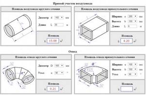
Calculation of rectangular and round pipes for ventilation
After determining the volume and flow rate, the cross-section of the outlet channel is calculated.
The diameter of the ventilation duct of a non-residential premises is calculated using the formula, which is the inverse of calculating the speed S = B / 3600 M, where:
- S—area (m2);
- B—flow velocity (m/s);
- M - flow rate (m3/h).
The result is used to calculate the diameter D = 1000 √ (4 S / π), where:
- D is the resulting diameter (m);
- S—calculated cross-sectional area (m2);
- π is a mathematical number (3.14).
The diameter result is compared with the parameters of the finished product and a product similar in size is selected. Determining the size of the channel, flow rate and air exchange rate is a complex calculation, so it is easiest to calculate ventilation by contacting specialist engineers.
The importance of air exchange for humans
According to construction and hygiene standards, every residential or industrial facility must be provided with a ventilation system.
Its main purpose is to maintain air balance and create a microclimate favorable for work and rest. This means that in the atmosphere that people breathe, there should not be an excess of heat, moisture, or pollution of various kinds.
Violations in the organization of the ventilation system lead to the development of infectious diseases and diseases of the respiratory system, decreased immunity, and premature spoilage of food.
In an excessively humid and warm environment, pathogenic microorganisms quickly develop, and pockets of mold and mildew appear on walls, ceilings and even furniture.
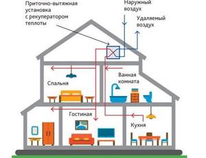
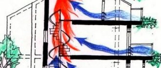
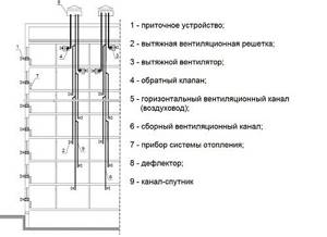
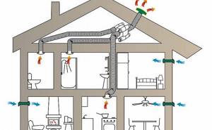
Ventilation diagram in a two-story private house. The ventilation system is equipped with a supply and exhaust energy-saving unit with a heat recuperator, which allows you to reuse the heat of the air removed from the building
One of the conditions for maintaining a healthy air balance is the correct design of the ventilation system. Each part of the air exchange network must be selected based on the volume of the room and the characteristics of the air in it.
Let’s assume that in a small apartment there is sufficiently well-established supply and exhaust ventilation, while in production workshops it is mandatory to install equipment for forced air exchange.
When constructing houses, public institutions, and workshops of enterprises, they are guided by the following principles:
- each room must be provided with a ventilation system;
- it is necessary to observe hygienic air parameters;
- enterprises should install devices that increase and regulate the air exchange rate; in residential premises - air conditioners or fans if there is insufficient ventilation;
- in rooms for different purposes (for example, in patient rooms and an operating room, or in an office and a smoking room), it is necessary to equip different systems.
In order for ventilation to meet the listed conditions, you need to make calculations and select equipment - air supply devices and air ducts.
Also, when installing a ventilation system, it is necessary to choose the correct air intake locations in order to prevent contaminated flows from flowing back into the premises.
In the process of drawing up a ventilation project for a private house, multi-storey residential building or industrial premises, the air volume is calculated and installation locations for ventilation equipment are outlined: water exchange units, air conditioners and air ducts
The efficiency of air exchange depends on the size of the air ducts (including house shafts). Let's find out what the standards for air flow speed in ventilation are, specified in the sanitary documentation.
Image gallery
Photo from
Ventilation system in the attic of a house
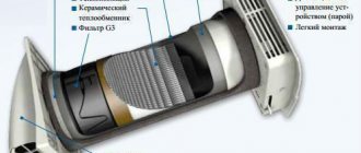
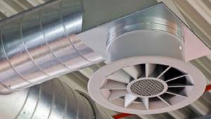
Supply and exhaust ventilation equipment
Rectangular plastic air ducts
Local resistance of air ducts
Purpose of calculation
Correct calculation allows you to balance the incoming and outgoing air flows.
The correctly selected size of ventilation shafts, risers and channels allows you to equalize the incoming and outgoing air volumes. As a result, the risk of respiratory diseases is reduced, comfort and sleep are improved, and performance increases.
If the calculation results in a volume of inflow mass greater than that of the outgoing mass, it is recommended to take the value at the maximum index. The Internet offers an online calculator to get the results; you only need to substitute individual values.
Recommended air exchange rate standards
As already mentioned, the speed of air flow through ventilation ducts is not standardized. But SNiP specifies recommended values for the speed of movement of air masses, which must be guided by when designing ventilation.
The permissible air speed in the air ducts is shown in the table:
| Type of duct and ventilation grille | Ventilation circuit type | |
| Natural | Forced | |
| m/s | ||
| Supply grilles (blinds) | 0.5-1.0 | 2.0-4.0 |
| Supply shaft channels | 1.0-2.0 | 2.0-2.6 |
| Horizontal composite (prefabricated) channels | 0.5-1.0 | 2.0-2.5 |
| Vertical channels | 0.5-1.0 | 2.0-2.5 |
| Grilles near the floor | 0.2-0.5 | 2.0-2.5 |
| Supply grilles near the ceiling | 0.5-1.0 | 1.0-3.0 |
| Exhaust grilles | 0.5-1.0 | 1.5-3.0 |
| Exhaust shaft channels | 1.0-1.5 | 3.0-6.0 |
The maximum recommended air flow speed in residential areas should not exceed 0.3 m/s. It is allowed to exceed it for a short time by up to 30%, for example, during repair work.
Proper duct equipment
Galvanized boxes can be round, square and rectangular in shape. Pipes are often installed to organize the supply flow in industrial and public premises. For installation, clamps are used that are attached to the ceiling with studs. Rectangular boxes are suspended on rigid traverses, where the height is adjusted with a control nut. Rubber gaskets are required.
Flexible air ducts up to 5 m long are laid without intermediate supports, longer pipelines are fixed with hangers and clamps on studs to avoid deflection. Despite the flexibility, such highways have certain radii beyond which it is not recommended to turn the route.
Causes and sources of noise in ventilation systems
Sources of noise in ventilation systems can be grouped as follows:
- Ventilation unit. In it, the source of increased noise is the rubbing parts of the electric motor and the fan. The situation is noticeably worsened by wear of the bearings, which is accompanied by crunching and grinding sounds, or incorrect selection of the size of the fan impeller.
- Air ducts. In them, noise appears as a result of the movement of air flow, changes in its direction and speed. When choosing air ducts, the thickness of their walls, cross-sectional area, the presence of seals, and the correct installation of distribution devices, valves, dampers and duct fittings are important.
The following errors in the design and installation of a ventilation system can increase noise:
- incorrectly selected power of the ventilation unit;
- the walls of the air ducts are too thin;
- incorrect selection of the air duct section;
- poor-quality installation, which leads to rubber seals and gaskets falling out of the joints of the air duct elements.
Noise from a ventilation system can travel in two ways: through the air (acoustic) or through building structures (structural). You need to fight them in different ways.
Ventportal
V. P. Gusev , Doctor of Engineering. sciences, head laboratory for noise protection of ventilation and engineering-technological equipment (NIISF)
In most cases, a very effective measure to combat noise in a ventilation system is the rational choice of parameters and quality of this system at the design stage, in particular, the choice of composition, length, optimal amount of supplied air, choice of fan, size of air ducts and flow rate in them, layout fittings.
When designing a ventilation system, it is necessary, first of all, to select air exchanges (amount of air) without excessive reserves, since with an increase in the amount of air, the speed of its movement in the air duct elements and their hydraulic resistance or transverse dimensions increase. The consequence of this is an increase in the flow of sound energy entering the room.
The resistance of the ventilation system is determined by the configuration and size of the air duct network, provided that the resistance is equal to the developed pressure of the fan.
The configuration of the ventilation system is usually determined by the layout conditions, and the dimensions are determined by efficiency, minimal dimensions and low noise generation in the shaped elements.
Assessment of the influence of ventilation system parameters on its noise level
The influence of the parameters of the ventilation system on its noise can be assessed using two equations, known from the works of E. Ya. Yudin, that are valid in the absence of back pressure, when the network resistance is equal to the total pressure of the fan:
- equation for the noise level in the room:
(1)
- equation of the air duct network in abstract coordinates:
(2)
where y is the pressure coefficient; f—flow coefficient; Q, D — air flow and diameter of the fan pipe (air duct); Fc is the cross-sectional area of the fan pipe (air duct); xc is the resistance coefficient, taking into account losses in shaped elements and straight sections of air ducts; B is a value that includes the fan similarity criterion and sound absorption in the room.
From equation (1) it is clear that at a constant operating point (y, f) on the dimensionless characteristic of the fan, the value D2/Fc is constant for a given xc.
This equation also makes it possible to evaluate the influence of duct network parameters, namely:
a) for a given network configuration and duct sizes, reducing the flow rate reduces the noise level by DL = 60lg Q2/Q1;
b) increasing the transverse dimensions of the air ducts reduces the noise level by an amount equal to DL = 50lg Fс2/Fс1;
c) reducing the network resistance coefficient is also an important means of reducing noise (DL = 30lg xc2/xc1), therefore one should strive to use shaped elements of a more advanced aerodynamic shape.
From equation (2) it follows that reducing the coefficient of hydraulic resistance of air ducts, increasing their cross-section and reducing, if possible, productivity results in energy savings. The power consumed by the fan is proportional to the product of air flow and the developed pressure, which is proportional to the square of the air speed through the duct.
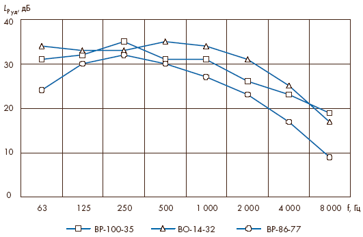
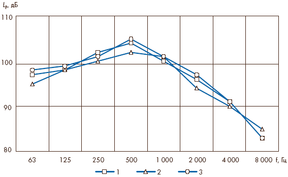
| Picture 1. Specific sound power levels of fans (discharge side) |
On the one hand, increasing the air flow speed makes it possible to reduce the cross-sectional area of the air duct, making it compact and thereby reducing manufacturing and installation costs. On the other hand, an increase in air flow speed will lead to the need to use high-pressure fans, and with the same performance as low-pressure fans, they consume higher (additional) energy and, therefore, have higher operating costs.
In each specific case, a compromise solution should be sought between these conflicting requirements.
Layout and layout of the ventilation system
When laying out and planning the ventilation system, it is advisable to be guided by the following considerations:
1. There should be no rooms near the ventilation chamber with a low level of intrinsic noise (when such rooms are located away from the ventilation chamber, noise transmission through the air ducts is reduced).
2. Extensive networks of air ducts or location of rooms at large distances from the fan should be avoided; in rooms that are located close to the fan, conditions are created that are unfavorable from an acoustic point of view, in which the peripheral speed and power of the fan, determined by the pressure for the distant area, are excessively high for the near room, and the amount of air entering the near room is unacceptably large, and Thus, the branch has to be throttled, thereby increasing the noise emitted by the system.
3. Throttle valves should be located as far as possible from the room being served, and behind them (in front of the grilles) end silencers or flexible air ducts with sound absorption should be provided.
4. In the air duct network, maximum air flow rates should be set based on the standards existing in ventilation practice, taking into account acoustic requirements.
5. The air distribution system must have minimal hydraulic resistance, since the generation of noise by a fan, regardless of its type, increases with the growth of the static pressure it develops.
6. At high noise levels, we must not forget about the use of silencers, providing places for their installation; Lack of space for a muffler is a common problem with many designs.
7. Aerodynamic, acoustic regulation and adjustment of the installed ventilation system should be carried out together, achieving the lowest noise level when supplying a given amount of air.
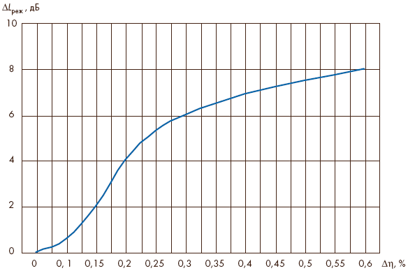
| Figure 2. Correction for fan operating mode. hD, % - deviation from hmax mode |
Fan selection
When selecting a fan, it is important to pay attention to the following conditions:
1. The fan must have the lowest specific sound power level (noise criterion) and the spectral composition of the noise corresponding to the specified operating conditions, with other optimal parameters and maximum efficiency (hmax).
2. The fan power must correspond to the hydraulic losses in the air duct network, i.e. its aerodynamic parameters must be selected in accordance with the technical needs of the project.
3. The use of fans with less than 12 blades should be avoided; they often generate intense tonal components of aerodynamic noise at the blade frequency and its harmonics; their intensity depends on the design of the fan, on the flow fluctuations at the impeller inlet and on the response of the air duct system.
4. The connected air ducts on the suction and discharge sides should be 2-3 times larger than the maximum size (diameter) of the fan pipe, they ensure uniform air flow; deviations from such patterns can significantly affect both the aerodynamic and acoustic characteristics of the fan.
5. In ventilation systems with controlled air flow, special attention should be paid to the effect of changing aerodynamic parameters on the sound power of the fan, for example, reducing the air flow by changing the angle of the blades can significantly increase the noise level.
6. Reducing the fan noise level can be achieved by reducing the rotation speed of the impeller within acceptable limits while maintaining its power (air flow and pressure).
7. It is recommended to install flexible inserts between the fan pipes and air ducts to relieve stress and prevent the transmission of vibration from the fan.
| Figure 3. Noise characteristics of fan VTs-14-46 No. 5 (discharge side):
|
Methods for measuring noise characteristics
Most types of fans are characterized by the existence of three independent paths of noise propagation: through the suction and discharge air ducts and through the walls of the housing into the surrounding space, i.e. the fan is considered as a combination of three separate noise sources. As a source of noise, a fan is represented using dimensionless and dimensional noise characteristics [1].
The dimensionless noise characteristic is the dimensionless spectrum of fan noise. It allows, based on the results of noise measurements of a fan of the same size D and at a peripheral speed u, to find the noise spectrum of the same fan at other sizes and speeds, keeping only the performance factor f constant. When recalculating, it is necessary to keep the same dimensionless frequencies f/n (n is the rotational speed of the impeller, rev/s) at the boundaries of the frequency measurement bands.
Dimensional noise characteristics are sound power levels in octave frequency bands. They are measured using standard methods. To implement standard methods for measuring noise characteristics, measuring chambers and test benches are required, the construction of which is associated with large material costs. Manufacturers have limited resources, so they provide characteristics of similar units or calculated data in the technical data sheets of fans. As a result, acoustic calculations performed on their basis do not reflect the real acoustic situation, and noise attenuation costs turn out to be overestimated or ineffective.
| Figure 4. Permissible flow rate in the end silencer depending on the purpose of the room served by the ventilation system |
In such cases, calculation methods become very relevant. The peculiarity of the domestic methodology for calculating octave sound power levels of fans was enshrined in the fundamental document in the field of noise control [2], which has been in force for about 30 years, in its manual [3] and is expressed by the semi-empirical formula:
| (3) |
where Lksh is the noise criterion, depending on the type and design of the fan, dB;
pn — total pressure created by the fan, kgf/m2;
Q—fan air volume flow, m3/s;
DLrez — correction for fan operating mode, dB;
DL1 — correction that takes into account the distribution of sound power over octave frequency bands and depends on the type and speed of the fan, dB;
DL2 - correction taking into account the acoustic effect of connecting the air duct to the fan, dB.
Using formula (3), the total sound power level of a domestic fan (for a given direction of noise emission) is first calculated based on its noise criterion, Lksh, and aerodynamic parameters at hmax. Then, using the DLrem correction, the change in this level in a given mode is taken into account, and using the DL1 correction, the octave levels of sound power of the noise emitted, for example, by the fan suction pipe into the surrounding space are determined. To determine the amount of sound power emitted into the connected duct, it is necessary to make a DL2 correction.
US companies and some European manufacturers use a shorter way to calculate the octave levels of sound power emitted by a fan into the connected air ducts, using a semi-empirical formula in the form:
| (4) |
where LPud is the specific sound power level in the octave frequency band, dB;
pn is the total pressure created by the fan, Pa;
DLf is the upward correction, dB, depending on the type of fan and taken into account in the octave band with blade frequency fl = zn, where z is the number of impeller blades, n is the rotation frequency, r/s. The remaining notations are as in formula (3).
As can be seen, in formula (4), in contrast to formula (3), not noise criteria are used, but specific sound power levels, LPud, are the sound power levels of a fan in octave frequency bands, developing a capacity of 1 m3/s and total pressure 1 Pa. The values of these specific sound power levels for different types of fans produced by US companies are contained in the reference book [4].
However, in domestic practice there are currently difficulties in determining the noise characteristics of fans. Firstly, in recent years the types and designs of fans produced in the country have changed, and accordingly, their acoustic characteristics (noise criteria) have changed. Secondly, SNiP has been terminated since January of this year [2]. The new document [5] does not contain methodological material, and a set of rules for it, regulating the calculation and design of noise attenuation of ventilation units, is not yet available.
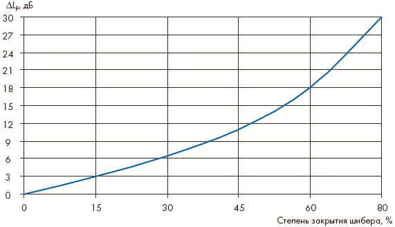
| Figure 5. Change in the noise level of the gate depending on the degree of its closure |
At NIISF, this problem is solved by using formula (4). To calculate the noise characteristics of domestic fans, which differ from foreign ones in a number of parameters, the laboratory of protection from ventilation and engineering-technological equipment has a bank of necessary data: specific sound power levels of the most common general industrial fans, corrections for their operating mode and corrections for the tonal component at frequency passage of the blades.
Spectrograms of noise, LP, of three types of centrifugal fans with impeller diameters of 500–800 mm are presented in Fig. 1. They are determined when the fans operate in a mode close to hmax. When deviating from the hmax mode, the fan sound power level increases by an amount corresponding to this deviation, as shown in Fig. 2.
Typical calculated data is illustrated in Fig. 3, where the sound power levels of the centrifugal fan VTs-14-46-5 are compared (at a flow rate of 15,000 m3/h, pressure of 2,500 Pa and rotation speed of 0.41 rps), calculated by formula (3), (4) and measured by standard methods (passport data).
Fan locations
When designing low-noise ventilation systems, it is important not only to accurately determine the noise characteristics, but also to correctly select the location of fans - the main sources of system noise. In the building being designed, fans should be located in isolated rooms (in ventilation chambers), remote from rooms with strict acoustic requirements, as well as from elevators, ventilation shafts and staircases, from doors and windows. In open areas, fans should be removed from reflective surfaces that form two- and three-sided angles, to places that ensure both minimal penetration of noise into the premises of a given building and its spread to the building area adjacent to the building, including residential areas . The outlets of air ducts (ventilation systems) into the atmosphere should be located in such a way that the noise emitted by the open ends is not directed towards residential buildings and recreational areas. Taking into account the direction of noise often serves as an effective measure of noise protection for the ventilation systems of these objects. In other words, proper vent orientation can achieve acceptable noise levels in the noise-protected area without significant expense.
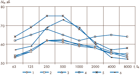
| Figure 6. Change in the noise level of the damper as it approaches the ventilation grille along the air duct (1-6 are the distances from the damper to the ventilation grille in calibers: 10, 8, 6, 4, 2 and 0.5 calibers, respectively) |
Air flow speed in ducts
Once the fan noise is reduced to the required level, the noise generated by the flow in the air duct elements becomes more pronounced. This noise is caused by pressure and velocity pulsations. It depends both on the speed of the oncoming flow, the coefficient of local resistance, the size and design of the air duct element, and on the degree of turbulence of the flow flowing onto it, the uniformity of the velocity field in the cross section of the air duct leading to it, and the location of the element in the air duct network. Thus, under poor conditions for the flow entering the air distribution device, the level of generated noise can increase by 5-15 dB [6].
The flow velocity in the air ducts must be below the limit values beyond which increased noise occurs. The criterion for determining the maximum possible air speed in air ducts can be the transverse dimensions and the minimum thickness of the steel sheet used for their manufacture (Table [7]).
| Table | ||
| 10 | 0,6 | |
| 900×1 200 | 9 | 0,8 |
| 1 200×1 800 | 8 | 1,0 |
As can be seen from the table, a maximum speed of 10 m/s is allowed in air ducts with walls 0.6 mm thick, but with a small cross-section; As the cross-sectional area of the ducts increases, it is necessary to increase the wall thickness and reduce the flow rate.
Unfortunately, the authors do not specify the purpose of the premises and buildings in the design of which this data can be used. Main (transit) air ducts cannot be laid through rooms that have high acoustic requirements. This is a very common design mistake, especially in theaters, temples, palaces and luxury housing.
Air flow speed in ventilation unit mufflers
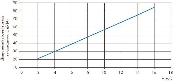
The permissible air speed in the muffler as an element of the ventilation system should be selected depending on the possible pressure losses and the permissible level of sound power generated in its noise flow path. Data on intrinsic noise generation in mufflers manufactured in accordance with SNiP [2] are contained in the manual [3]. When the muffler is installed at the end of the duct (at the entrance to the room), the air speed limitation may be related to the permissible sound pressure levels in the rooms served by the systems. For premises of residential, public, administrative and industrial buildings, this relationship is demonstrated in Fig. 4. It can be seen that when servicing, for example, a musical theater hall, the speed in the end muffler should not exceed 4 m/s, and in an office - 6 m/s. In the free cross-section of the central silencers of ventilation units, the permissible speed can be twice the values shown in Fig. 4, but not more than 15 m/s, to avoid blowing out sound-absorbing material from them.
Influence of throttling devices on noise level
In the branches of the main air duct, throttling devices are installed in each branch of the ventilation network to ensure a given air flow. Noise generation in these devices depends on their local resistance coefficient. The noise levels of the throttle valve depending on the degree of opening (closing) of the damper are shown in Fig. 5. It shows how, as the throttling device closes, the hydraulic resistance and generated noise increase. If a throttling device with a coefficient of more than 5 is required, then it is better to install several devices in series that together provide the required resistance [7].
Throttling elements (gates, throttle valves, etc.), which create open vortex zones in air ducts, are sources of increased noise. It is necessary to strive to ensure that these vortex zones are closed. This condition provides a section of the air duct between the throttling element and the open end of the channel (grid) with a length of at least 8-10 N, where N is the size of the obstacle (length of the gate, projection onto the cross-sectional plane of the throttle valve, etc.). As the distance from the throttle installation site to the grille increases, the noise level decreases significantly (Fig. 6) [8].
As can be seen in Fig. 6, curves 1, 2 and 3 correspond to noise levels with a closed vortex zone and the length of the channel behind the gate of 10, 8 and 6 gauges. As the vortex zone opens, the noise increases in the low and high frequency bands of the spectrum (curve 4). This is explained by an increase in impulse exchange between the main flow in the channel and the open vortex zone into which air is sucked from outside. In this case, small-scale eddies appear at the edge of the channel, which, in all likelihood, cause an increase in noise levels in the high-frequency part of the spectrum. Further reducing the length of the channel behind the gate to two calibers increases the noise intensity in the low and medium frequencies; in the high-frequency part of the spectrum the noise level decreases. When the channel length behind the gate is 0.5 caliber, a decrease in noise intensity is observed and the maximum in the spectrum occupies the mid-frequency region. In this case, the vortex zone is completely opened and the flow behaves like a free jet.
The influence of air intake and air distribution grilles on noise levels
High velocities in air intake and air distribution grilles also cause increased noise levels in the room. Exceeding the permissible air speed by 10% leads to an increase in noise level by 2 dB. Doubling the permissible air speed can lead to an increase in noise levels by 10-12 dB. The grilles must be connected to the air duct along one axis. Deviation from this requirement leads to an increase in noise level, which in some cases can reach 12-15 dB. When the flow is throttled by the grille guide dampers, the noise level changes by 12 dB [7].
It is not recommended to install more than 4-5 air distributors in series on one air duct, since in this case the air pressure in front of the first air distributor may be so high that it may be necessary to install a throttling device with a large coefficient of local resistance (with a large cover), which will inevitably lead to an increase in the noise it creates.
After the above basic acoustic requirements and design rules for ventilation systems have been taken into account, it is necessary to perform an acoustic calculation [3]. Its result will be a frequency-dependent value of the required noise reduction, which, in turn, is the basis for the design of noise attenuation, ensuring regulatory requirements for the noise factor in human habitats, both in buildings and in buildings, including residential.
The volume of means and methods for combating ventilation noise is quite large and continues to increase. Therefore, in each specific situation, it is important to correctly determine the necessary complex that provides the required efficiency and minimal material costs for its implementation. The goal is achieved, as a rule, in cases where the designer has the most complete information about the scope and capabilities of modern means and methods of noise control.
These issues, as stages on the way to protecting ventilation systems from noise, will be the subject of articles that are expected to be submitted for publication in the journal by the end of this year.
Literature
1. Centrifugal fans / Ed. T. S. Solomakhova. M.: Mechanical Engineering, 1975.
2. SNiP II-12-77. Noise protection.
3. Guide to the calculation and design of noise suppression of ventilation units. M.: Stroyizdat, 1982.
4. ASHRAE HANDBOOK. Sound and Vibration Control. 1987.
5. SNiP 23-03-2003. Noise protection.
6. Noise reduction in buildings and residential areas / Ed. G. L. Osipova, E. Ya. Yudina. M.: Stroyizdat, 1987.
7. Ventilation and air conditioning systems. Theory and practice. M.: Euroclimate, 2000.
8. Leshko M. Yu. Influence of the connected air duct on the noise created by the control damper // Sat. scientific tr. M.: NIISF, 1979.
Published in ABOK magazine No. 4/2004
Types of ventilation equipment
Ventilation is a process that should create a favorable atmosphere in the premises. At industrial enterprises, various harmful impurities are often observed in the air, and they are sometimes not entirely safe for the health of workers. Without high-quality circulation, the atmosphere in such an enterprise will be unsuitable for work.
The classification of this process can be approached from different angles and, depending on the criterion, the types of ventilation can be different.
Depending on the method of organizing air exchange, it can be either natural or forced.
According to its intended purpose, the system can be:
- Supply.
- Exhaust.
By area that is ventilated:
- General exchange.
- Local.
According to the design of the ventilation system, it can be:
- Channel.
- Ductless.
Before making a choice, you need to pay attention to:
- Industrial plant area.
- Ceiling height.
- Amount of workers.
- Location of workplaces.
- Shift duration.
- Types of work performed at the enterprise.