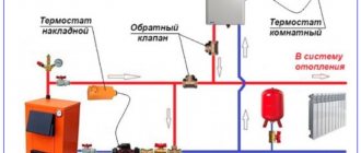
How to choose emergency valves
To successfully select a thermal relief or overpressure valve, follow these guidelines:
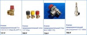
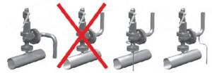
- When using any energy carriers other than solid fuel, feel free to buy a regular blasting device.
- Study the documentation of your heat source or boiler (depending on what needs to be protected) and select safety fittings according to the maximum permissible pressure indicated therein. Most heating equipment is designed for a limit of 3 Bar, although there are exceptions - Lithuanian Stropuva boilers can withstand only 2 Bar, and some Russian units (among the inexpensive ones) can withstand 1.5 Bar.
- To effectively cool wood-burning heat generators in the event of an accident, it is better to install one of the thermal relief valves. Their maximum operating pressure is 10 Bar.
- In open systems with a TT boiler, pressure relief is useless. Select a safety product that operates at a coolant temperature of 95–100 °C, suitable for your unit and recharge method.
Advice. Refrain from purchasing cheap safety valves from China. Not only is it unreliable, but it also leaks after the first explosion.
In addition to products with fixed settings, there are valves with adjustable settings on sale. If you are not a heating professional, then you should not buy them, and there is no particular need.
Types of security groups and the principle of choosing the appropriate model
A standard safety valve for a boiler may differ in design in several design features. These nuances do not change the functionality of the device, but only simplify use and maintenance. To choose the right safety unit, you need to know what safety valves for boilers are and how they differ.
Lever models
The most common type of standard safety assembly is the lever model. This mechanism can be activated manually, which is convenient when checking or draining water from the boiler tank. They do it like this:
- A horizontally located lever is installed vertically;
- direct connection to the stem activates the spring mechanism;
- the safety valve plate forcibly opens the hole and water begins to flow from the fitting.
Even if the tank is not completely emptied, a control drain is performed monthly to check the functionality of the safety unit.
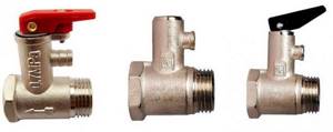
The products differ in the design of the lever and the fitting for discharging water. If possible, it is better to choose a model with a flag fixed to the body. The fastening is made with a bolt that prevents children from manually opening the lever. The product has a convenient herringbone-shaped fitting with three threads, which ensures reliable fixation of the hose.
The cheaper model does not have a flag lock. You can accidentally catch the lever with your hand and unnecessary drainage of water will begin. The fitting is short, with only one threading ring. It is inconvenient to fix the hose onto such a protrusion and can tear it off under strong pressure.
Models without lever
Safety valves without a lever are the cheapest and most inconvenient option. Such models often come complete with a water heater. Experienced plumbers simply throw them away. The units operate similarly to lever models, but there is no way to manually perform a control drain or empty the boiler tank.
Models without a lever come in two versions: with a cover at the end of the body and blind. The first option is more convenient. If clogged, the cover can be unscrewed to clean the mechanism. A blind model cannot be tested for functionality and cannot be descaled. The fluid discharge fittings for both valves are short with one threaded ring.
Safety components for large water heaters
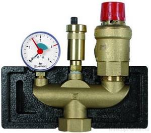
Water heaters with a storage tank volume of 100 liters or more are equipped with improved safety valves. They work in a similar way, only they are additionally equipped with a ball valve for forced drainage, as well as a pressure gauge.
Particular attention should be paid to the fluid drainage fitting. It's threaded. Reliable fastening prevents the hose from being torn off by strong pressure and eliminates the inconvenient use of the clamp
Reliable fastening prevents the hose from being torn off by strong pressure and eliminates the inconvenient use of the clamp.
Original models
For lovers of aesthetics and comfort, manufacturers offer original safety components. The product is equipped with a pressure gauge, chrome plated, and given an elegant shape. The products look beautiful, but their cost is high.
Difference in body markings
High-quality products must be marked on the body. The manufacturer indicates the maximum permissible pressure, as well as the direction of water movement. The second marking is an arrow. It helps to determine which side to place the part on the boiler pipe.
On cheap Chinese models there are often no markings. You can figure out the direction of the liquid without an arrow. The check valve plate must open upward in relation to the boiler pipe so that water from the water supply flows into the tank. But it’s impossible to determine the permissible pressure without markings. If the indicator does not match, the safety unit will constantly leak or will not work at all in an emergency.
Other types of valves
When they try to save money on a safety group, they try to install a blast valve designed for the heating system on the water heater. The nodes are similar in functionality, but there is one nuance. The blast valve is not capable of releasing liquid little by little. The mechanism will work when the excess pressure reaches a critical point. The blast valve can only release all the water from the tank in the event of an accident.
Separately, it is worth considering installing only a check valve. The mechanism of this unit, on the contrary, locks the water inside the tank, preventing it from draining into the pipeline. If there is excess pressure, the working plate with the rod is not able to work in the opposite direction, which will lead to rupture of the tank.
Calculation
The calculation of the safety device must be carried out in accordance with the methodology presented in SNiP II-35 “Boiler installations”.
Since manufacturers rarely indicate the actual height of the rod lift in the technical specifications, in the calculation this parameter is equal to 1/20 of the seat diameter. For this reason, the valve size as a result of this calculation is somewhat overestimated. In any case, after selecting a device, it is necessary to compare the thermal power of the heating system with the maximum power recommended in the technical description for the selected standard size.
Installation of a safety valve is required to protect the heating system from exceeding the pressure level above the maximum permissible value. For this reason, the calculation of this device should be reduced to calculating the maximum permissible increase in coolant volume and identifying possible sources of excess pressure.
Sources of volume growth can be:
- Overheating in a heat exchange or boiler unit with subsequent vaporization. When vaporizing, a liquid can increase its volume by 461 times, so this factor is the predominant factor when choosing a valve.
- Failure of automatic control of make-up lines of boiler houses and independent heating systems. This may also be a predominant factor in valve selection.
- The coolant, heating up in a heat exchange or boiler unit, increases in volume. When heated, the specific volume increase is from 0 to 100 °C, which is only 4%, so when selecting the size of a device of this type, this is not a fundamental point.
The selected equipment must ensure the discharge of the calculated amount of coolant, according to the most significant factor in the increase in volume.
Table A.6
| β | The value of B3 at k equal to | |||||||
| 1,135 | 1,200 | 1,300 | 1,400 | 1,660 | 2,0 | 2,5 | 3,0 | |
| 0,100 | 0,715 | 0,730 | 0,755 | 0,770 | 0,820 | 0,865 | 0,930 | 0,960 |
| 0,200 | ||||||||
| 0,300 | ||||||||
| 0,354 | ||||||||
| 0,393 | 0,959 | |||||||
| 0,400 | 0,929 | 0,957 | ||||||
| 0,445 | 0,928 | 0,950 | ||||||
| 0,450 | 0,864 | 0,925 | 0,942 | |||||
| 0,488 | 0,863 | 0,920 | 0,935 | |||||
| 0,500 | 0,819 | 0,860 | 0,919 | 0,933 | ||||
| 0,528 | 0,819 | 0,853 | 0,912 | 0,925 | ||||
| 0,546 | 0,769 | 0,816 | 0,850 | 0,902 | 0,915 | |||
| 0,550 | 0,754 | 0,768 | 0,816 | 0,845 | 0,900 | 0,914 | ||
| 0,564 | 0,753 | 0,765 | 0,815 | 0,842 | 0,899 | 0,911 | ||
| 0,577 | 0,729 | 0,752 | 0,764 | 0,810 | 0,840 | 0,898 | 0,900 | |
| 0,600 | 0,714 | 0,725 | 0,750 | 0,762 | 0,805 | 0,835 | 0,877 | 0,880 |
| 0,650 | 0,701 | 0,712 | 0,732 | 0,748 | 0,773 | 0,800 | 0,848 | 0,850 |
| 0,700 | 0,685 | 0,693 | 0,713 | 0,720 | 0,745 | 0,775 | 0,810 | 0,815 |
| 0,750 | 0,650 | 0,655 | 0,674 | 0,678 | 0,696 | 0,718 | 0,716 | 0,765 |
| 0,800 | 0,610 | 0,613 | 0,625 | 0,630 | 0,655 | 0,670 | 0,700 | 0,705 |
| 0,850 | 0,548 | 0,550 | 0,558 | 0,560 | 0,572 | 0,598 | 0,615 | 0,620 |
| 0,900 | 0,465 | 0,468 | 0,474 | 0,475 | 0,482 | 0,502 | 0,520 | 0,525 |
| 1,000 | 0 | 0 | 0 | 0 | 0 | 0 | 0 | 0 |
Determination of the conditional cross section and response threshold
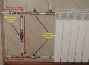
It is easy to determine the cross-section of the emergency valve - it must be no less than the diameter of the supply pipe. Otherwise, it will not work as it should. When installing not as part of a safety group, we make the tap with a slight slope towards the boiler (it can be vertical, but definitely not in the opposite direction). If your wiring is inch, we use the same pipe to make an outlet, and install a blast valve of the same cross-section. This is understandable.
Can be part of a security group or installed separately
The response threshold is determined based on the operating pressure of the system. For normal operation it should be 20-30% higher. If your heating operates at 1.2 Bar, then the excess pressure relief valve should operate at 1.45-1.55 Bar.
It is not always possible to find an emergency valve with the required response value. You can either take one with similar parameters, or find an adjustable one (there is one for 1.5 Bar).
Why is the emergency valve leaking?
If a puddle appears under the safety valve, it is necessary to inspect the system. If you do not pay attention to this symptom for a long time, the boiler may even explode. So let’s immediately check the possible reasons:
- The pressure in the expansion tank is too low and it cannot cope with the task. Check the pressure in the membrane tank. To do this, there is a spool in the upper part; we connect a pressure gauge to it and look at the readings. It should be 0.2-0.5 bar less than the operating pressure of the system. If it’s too low, take a pump and pump it up through the same spool.
- The membrane in the membrane tank is damaged. The solution is to change the membrane or install a new tank.
- The membrane tank is smaller than required for the system (10% of the system volume). If the volume is really small, we either install a second tank or change it to a larger one.
- The coolant overheats (boils). To solve the problem, circuit solutions are required; circuit modernization is required. A more gentle but temporary solution is to reduce the intensity of combustion.
If you do not pay attention to the dripping blast valve, the boiler may burst
Once again, we draw your attention to the fact that a puddle under the emergency valve is a cause for concern and a signal that it is necessary to inspect the system components responsible for stabilizing the pressure.
Varieties
Existing types of valves are capable of working with boiler equipment from leading foreign (Vaillant, Baxi, Ariston, Navien, Viessmann) and domestic (Nevalux) manufacturers using gas, liquid and solid fuels in situations where automatic control of the system operation due to the type of fuel is difficult or broken when the automation fails. Depending on their design and operating principle, safety valves are divided into the following groups:
- According to the purpose of the equipment in which they are installed:
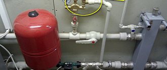
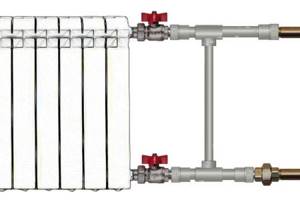
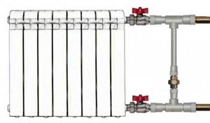
- For heating boilers that have the above design, they are often supplied on fittings in the form of a tee, into which a pressure gauge is additionally installed to check the pressure and a venting valve.
- For hot water boilers, the design includes a flag for draining water.
- Tanks and pressure vessels.
- Pressure pipelines.
- According to the operating principle of the clamping mechanism:
- From a spring, the clamping force of which is regulated by an external or internal nut (its operation is discussed above).
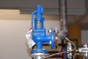
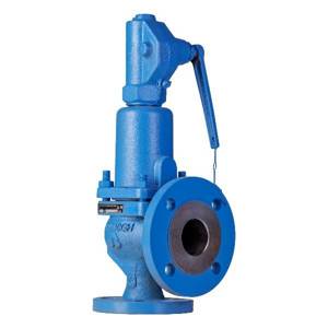
- Lever-load type, used in industrial heating systems designed to discharge large volumes of water; their response threshold can be adjusted by hanging weights. They are suspended on a handle connected to the shut-off valve using a lever principle.
Lever-load modification device
- Locking mechanism speeds:
- Proportional (low-lift spring) - the sealed lock rises in proportion to the pressure and is linearly related to its increase, while the drain hole gradually opens and closes in the same way with a decrease in the volume of coolant. The advantage of the design is the absence of water hammer under various modes of movement of the shut-off valve.
- Two-position (full-lift lever-load) - operate in open-closed positions. When the pressure exceeds the response threshold, the outlet hole opens completely and the excess coolant volume is released. After the pressure in the system is normalized, the outlet is completely blocked; the main drawback of the design is the presence of water hammer.
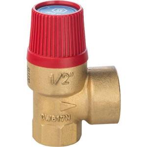
- By adjustment:
- Non-adjustable (with caps of different colors).
- Adjustable screw parts.
- According to the design of the spring compression adjusting elements:
- An internal washer, the operating principle of which was discussed above.
- External screw, nut, models are used in domestic and communal heating systems with large volumes of coolant.
- Using a handle, a similar adjustment system is used in flanged industrial valves; when the handle is fully raised, it is possible to perform a one-time release of water.
Designs of various models of drain valves
Why might a valve leak?
The pressure relief valve in the heating system can leak for various reasons. In some situations, this is an acceptable natural process; in other cases, a leak indicates a malfunction of the device.
Leakage of the protection valve can be caused by the following reasons:
- Damage to the sealed rubber cup or disc as a result of repeated use. If during repairs a replacement part cannot be found on sale or is not included in the package, you will have to replace the device completely.
- In spring types, the opening of the side drain pipe occurs gradually; at borderline pressure values or short-term surges, the valve may partially operate and drip, which does not indicate its malfunction.
- Leakage can be caused by incorrect settings or malfunctions of the expansion tank - damage to its membrane, air escaping through a depressurized housing or a damaged nipple. In this case, sharp pressure surges are possible as a result of water hammer, causing periodic short-term leakage of coolant through the safety valve.
- The cause of leakage in some adjustable valves is fluid seeping down the stem through the top during actuation.
- If a back pressure is created at the outlet pipe above the device's response threshold, a leak will also occur.
Appearance, cost of some brands of drain valves
The safety valve of steam boilers is designed to protect them from excess pressure in the system caused by various factors, and is a mandatory element when operating this type of equipment. There is a wide range of safety devices on sale from Chinese, domestic and European manufacturers, which are characterized by a relatively low cost. When purchasing, it is rational to choose a protective group from several devices, which additionally includes a pressure gauge and an air release valve.
How to set a safety valve
The valve must be adjusted at the installation site after completion of installation work and after the system has been flushed. Set the setting pressure, check the opening and closing pressure of the product.
The settings should be set slightly above the maximum operating pressure, which is permissible during normal operation of the structure. And the full opening pressure should not be higher than the minimum level of the weakest element of the system. The closing pressure must exceed the minimum permissible value.
The pressure in the spring structure must be adjusted by rotating a special screw that compresses the spring, and the lever structure is adjusted using the required mass of the load.
So, the valve is ready for operation if it is able to ensure the tightness of the overlap, as well as the complete opening and closing of the valve. In addition, the pressure may deviate within the permissible fluctuations, which are given in the technical data sheet of the product.
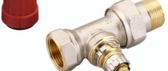
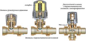
Features of choosing three-way thermostatic valves:
Non-return safety valve for boiler
Adjusting the pressure in a private house in the heating system
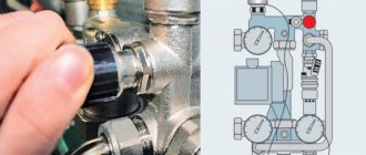
How it works and works
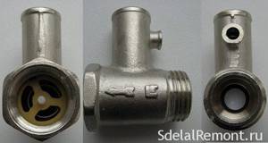
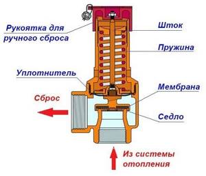
When talking about a safety valve for a water heater, it is better to use the phrase “valve system”, because there are two of them in the device.
Boiler safety valve device
They are located in a brass or nickel-plated body. A check valve is installed at the bottom of the housing, which, when the pressure in the system decreases, prevents the outflow of water from the water heater. In the perpendicular branch there is a second valve, thanks to which, at the moment of increasing pressure, part of the water is released through the fitting.
How does a safety valve work?
Principle of operation:
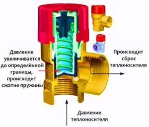
- While the pressure is normal, the valve is closed and does not allow liquid to flow out; as soon as it becomes equal to the pressure in the water supply, the spring presses the plate against the protrusions of the body and blocks the flow of water.
- When the heating is turned on, the water temperature gradually increases, and the pressure also increases with it.
- As soon as the pressure exceeds the force of the spring, an exit to the fitting opens through which excess water is drained. When the pressure returns to normal, the spring closes the passage and the flow of water stops.
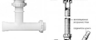
Based on the principle of operation, it becomes clear that water will constantly drip from the fitting. To drain the draining liquid, you need to put a tube of the appropriate diameter on the pipe and secure it with a clamp. The pressure required for normal operation of the water heater is 6-10 Bar.
The tube to the fitting must be transparent so that you can control the operation of the device.
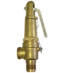
Lever-weight safety valves
The basis of the mechanism of this type of valve is a lever and a weight suspended on it. The operation of the device depends on the weight of the weight and its location on the lever. The greater the weight and the further it is on the lever, the higher the pressure the valve operates.
Lever weight safety valve design.
Adjustment of the lever-weight valve, as noted above, is carried out by moving the weight along the lever. After the required pressure has been adjusted, the load is secured with bolts, covered with a protective casing and locked. This is done to prevent unauthorized changes to the settings.
The lever-load design is as reliable as the spring one, however, its disadvantages include higher cost, as well as the fact that lever safety valves are produced only for flange connections with a diameter of DN50 and above.
The main types of safety valves: spring, lever-load.
Choice
When choosing a safety valve, you should consider some parameters:
the range of values at which the valve operates (it is important to take into account the parameters of your heating system and select a device based on them); type of valve - open/closed (if we are talking about an open one, then the coolant will be discharged into the atmosphere, when using a closed one - into the return pipeline); permissible height to which the plate rises (this indicator is selected based on throughput). Before purchasing and installing a safety valve, you should take into account the technical components of your heating system: boiler power and the maximum permissible medium pressure in the pipeline
Before purchasing and installing a safety valve, you should take into account the technical components of your heating system: boiler power and the maximum permissible medium pressure in the pipeline.
Application area
This standard applies to vessels for various liquid and gaseous media operating under pressure above 0.07 MPa (0.7 kgf/cm2), equipped with safety valves designed to protect against emergency pressure increases by releasing (dumping) the working medium from the vessel through valve. The standard establishes general safety requirements for the selection, installation and operation of safety valves, and also establishes a procedure for calculating the capacity of safety valves. This standard does not apply to vessels operating under vacuum.
Calculation
The calculation of the safety device must be carried out in accordance with the methodology presented in SNiP II-35 “Boiler installations”.

Since manufacturers rarely indicate the actual height of the rod lift in the technical specifications, in the calculation this parameter is equal to 1/20 of the seat diameter. For this reason, the valve size as a result of this calculation is somewhat overestimated. In any case, after selecting a device, it is necessary to compare the thermal power of the heating system with the maximum power recommended in the technical description for the selected standard size.
Installation of a safety valve is required to protect the heating system from exceeding the pressure level above the maximum permissible value. For this reason, the calculation of this device should be reduced to calculating the maximum permissible increase in coolant volume and identifying possible sources of excess pressure.
Sources of volume growth can be:
- Overheating in a heat exchange or boiler unit with subsequent vaporization. When vaporizing, a liquid can increase its volume by 461 times, so this factor is the predominant factor when choosing a valve.
- Failure of automatic control of make-up lines of boiler houses and independent heating systems. This may also be a predominant factor in valve selection.
- The coolant, heating up in a heat exchange or boiler unit, increases in volume. When heated, the specific volume increase is from 0 to 100 °C, which is only 4%, so when selecting the size of a device of this type, this is not a fundamental point.
The selected equipment must ensure the discharge of the calculated amount of coolant, according to the most significant factor in the increase in volume.
Tips for choosing the optimal model
Before choosing a specific safety equipment, you must familiarize yourself in detail with the technical characteristics of the boiler installation.
Do not neglect to study the manufacturer’s instructions, which indicate all the limit values.
Several criteria play a decisive role in choosing a heating device:
- Boiler performance.
- The maximum permissible medium pressure for the thermal power of heating equipment.
- Safety valve diameter.
You should check that the pressure regulator in the device has a range that includes the parameters of a particular boiler. The response pressure should be 25-30% greater than the operating pressure required for stable operation of the system.
The diameter of the safety valve cannot be less than the connector of the inlet pipe. Otherwise, constant hydraulic resistance will not allow the fuse to fully perform its immediate tasks.
The optimal material for manufacturing equipment is brass. It has a low coefficient of thermal expansion, which prevents destruction of the housing from exposure to strong pressure.
The control unit is made from heat-resistant plastic materials that maintain the required rigidity even when in contact with boiling liquid.
Flow control valve
The regulating safety valve allows you to set and stabilize the parameters of the heating system at a level that is safe and convenient for maintenance. There are several types of such valves.
Types of control valves
The pressure reducing valve regulates the flow of coolant by changing the cross-section of the inlet pipe.
The lever valve or lever-and-weight valve is used in large systems containing large diameter pipes. It has a spool that opens the pressure relief valve. The spool is activated when the pressure exceeds the force of the lever with weights, and the number of weights is adjustable.
The pressure valve installed in closed systems allows you to set the response level manually, and with the help of a mechanically adjustable thermal head it is easy to adjust the response via a servo drive.
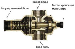
Design of a water pressure regulator with a threaded valve
The bypass valve reduces and stabilizes the coolant pressure; it must be installed instead of the relief valve. It increases the operating temperature of the medium in the return pipeline, returning a portion of excess water or oil to the line, and under pressure, the level of which is regulated. It is installed immediately behind the circulation pump or a group of such pumps, connecting at the inlet to the supply pipe, and at the outlet to the return pipe.
Bypass in the heating system
A water heating system is a complex structure that, in addition to a heat source and pipeline, includes heat exchangers, pumps and shut-off and control valves. To ensure efficient operation of the network and the ability to replace individual elements if damaged, it is necessary to provide a bypass circuit for the coolant. Installing a heating bypass allows you to turn off a certain section of the heating network for maintenance and repair work.
Purpose and scope of application
What is a bypass? It is a jumper in the form of a piece of pipe, the diameter of which should be smaller than the cross-section of the supply pipes. The bypass is installed parallel to the main pipeline through which the coolant circulates. Depending on its location, it can perform the following tasks:
- regulate the amount of working medium. If there is an excess of coolant, the jumper allows you to reduce its volume and return the excess to the vertical riser of the heating network. Adjustment of the flow of the working medium is in demand in two-pipe heating systems and can be carried out manually or automatically;
- improve heating efficiency. In single-pipe heating systems, radiators are connected in series, which makes it difficult to control the temperature of the coolant and ensures uneven heating of the rooms. Why is bypass needed in such networks? It allows you to create a workaround for the working environment and makes it possible to maintain its temperature within specified limits using a thermostat. In addition, thanks to a jumper in the form of a pipe section, individual radiators are disconnected for repair and replacement of pipeline fittings.
Why else would you need a bypass? It is in demand in autonomous heating systems of private houses, the design of which involves the movement of coolant under the influence of a circulation pump. When there is a power outage, power to the equipment stops and forced movement of the working environment becomes impossible. The bypass allows you to establish natural circulation of the coolant and ensures the uninterrupted functioning of the heating network. The heating system can be switched manually or automatically.
Installation Features
1. valve or thermostatic valve 2. shut-off valve (detentor) 3. air release valve (Mayevsky valve) 4. plug 5. valve 6. bypass
The bypass installation technology is determined by its purpose and location. In heating systems with a single-pipe or two-pipe connection scheme, it should be located as close as possible to the battery. When installing a jumper on a heating radiator, the following rules must be observed:
- Shut-off taps or valves are installed between the battery and the bypass to shut off the coolant flow;
- When connecting the pipe to the radiator, it is equipped with a thermostat, which serves to control the temperature in the room.
In autonomous systems with a gas or solid fuel boiler, the installation of a bypass to ensure natural movement of the working medium when disconnected from electricity is carried out together with the pump. For piping, you should use a jumper, the material of which coincides with the main pipe, and the cross-section is half its diameter. In addition to the circulation pump, the following is installed on the bypass:
- a mesh filter that protects devices from large debris and damage from scale and rust particles;
- check valve When the power is turned off, it prevents the coolant from moving along the small circuit on which the pump is located.
The check valve allows you to switch the circulation of the working medium from forced to natural in automatic mode. For manual adjustment, shut-off valves are placed on the bypass and main pipe.
Installation of equipment on the jumper should occur in the direction of movement of the coolant. Upon completion of installation, to check the tightness of the heating system, pressure testing is performed, which should be 1.5 times greater than the calculated one.
List of additional equipment
In order for the bypass to perform its functions, it is necessary to use pipeline fittings during its installation. TM Ogint offers a large selection of equipment for heating systems that will ensure efficient operation of communications. All manufactured products are manufactured in accordance with the requirements of European GOSTs and are intended for use in Russian Federation conditions. The list of proposed equipment includes:
- shut-off valves. They serve to shut off the flow of coolant during maintenance or repair work and allow flushing of the system. In addition, with the help of shut-off valves, it is possible to control the circulation of the working medium manually;
- thermostats. The devices are designed to maintain a given temperature in the room and ensure the creation of a comfortable microclimate. Ogint's range includes a thermostatic manual valve and an ICMA thermostatic element.
To remove excess air from the batteries from the network, you should use Mayevsky taps of various designs. In distribution systems of central communications, automatic devices are used, and fittings with a cap or a screwdriver are installed on radiators in an apartment or private house.
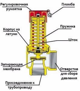
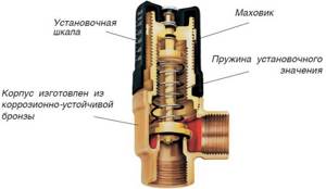
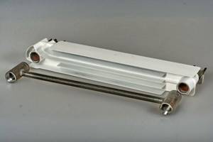
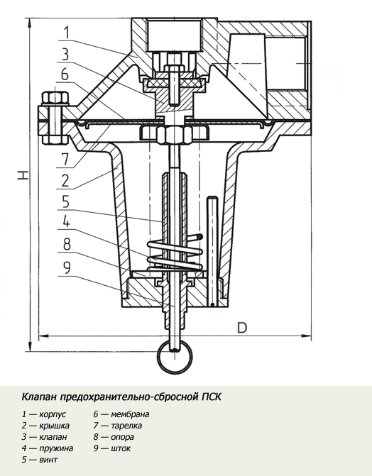
Design
A valve in a heating system consists of a body and two cast parts, which are manufactured in a semi-solid state. The body is made of plumbing brass, which is produced using hot stamping technology
A very important component of this part is the spring, which is made of steel. It establishes pressure force using its elasticity
This pressure will act on the membrane, which closes the passage to the outside.
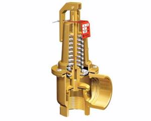
Rice. 1 Safety device made of brass
The membrane, in turn, is pressed by a spring, and is also located in a seat, which is equipped with a seal. The spring rests on top of a metal washer, which is fixed to the rod and screwed to a handle made of plastic. This handle is needed to adjust the valve in the heating system. The membrane and components of the relief valve and seals are made of polymer materials.
Purpose
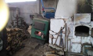
The relief safety valve protects the heating system from the consequences associated with overheating of the coolant. This device is a necessary attribute of the piping of a solid fuel boiler, and is also part of the heating system with a heat exchanger installed in the furnace.
Unlike liquid fuel, gas and electric boilers, solid fuel units are characterized by great inertia and the inability to quickly regulate the heating intensity of the liquid in the water jacket or heat exchanger. When overheated, the coolant boils, and as a result of vaporization, the pressure in a closed volume increases sharply.
This could turn out to be
:
- leaks at the junctions of pipeline elements;
- damage to fittings and pipes made of polymer material;
- explosion of the boiler water jacket, which is dangerous for people and can cause a short circuit of electrical equipment in the boiler room.
An overpressure relief valve can be installed separately, but usually this device is part of a safety group complete with a pressure gauge and air vent.
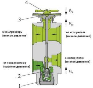
The purpose and operating principle of three-way safety valves is somewhat different from other options, and here are their key differences:
- use is permissible in low-temperature heating systems for media cooling;
- it is possible to adjust the product manually or using an electric drive;
- the presence of one inlet and two outlets;
- To regulate the flow, there is a special valve in the form of a ball or rod that directs it to the desired hole.
Such valves are most often used in heating systems that include “warm floors”. In this way, the water for heating the floors will be much cooler than the water in the radiator.
For the manufacture of three-way safety valves the following is used:
- steel;
- brass;
- cast iron.
Brass designs are most common when installing home heating systems, while steel and cast iron are more common in larger industrial installations.
It is also worth paying attention to the explosion safety valve, which can prevent the explosion of flammable gases or coal dust. They are made in such a way that if the substance explodes, only the membrane of the structure is damaged, and the pipeline remains unharmed.
This type of product operates automatically. Depending on the pressure, they are distinguished into several types:
- with pressure up to 2 kPa;
- up to 40 kPa;
- 150 kPa inclusive.
Installation Features
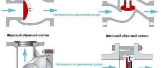
When installing check valves in heating, you must follow several rules:
- The valve is installed in the direction of the coolant. To avoid installation problems, there is a direction arrow on the housing.
- To seal the valve, paronite gaskets are used, only taking into account that the diameter of the hole does not decrease.
- It is advisable to install a coarse mesh in front of the valve to prevent small particles from entering the mechanism and causing damage.
- The valve is installed so that other components do not interfere with its operation. This will relieve additional pressure on the valve.
Requirements for inlet and outlet pipelines
7.1. Valves should be installed on pipes or pipes directly connected to the vessel. When installing several valves on one branch pipe (pipeline), the cross-sectional area of the branch pipe (pipeline) must be at least 1.25 of the total cross-sectional area of the valves installed on it. When determining the cross-section of connecting pipelines with a length of more than 1000 mm, their resistance must also be taken into account. 7.2. The pressure drop in front of the valve in the supply pipeline at maximum capacity should not exceed 3% of the set pressure. 7.3. The valve piping must provide the necessary compensation for thermal expansion. The fastening of the valve body and piping must be designed taking into account static loads and dynamic forces arising when the valve operates. 7.4. The supply pipelines must be made with a slope along the entire length towards the vessel. In supply pipelines, sudden changes in wall temperature (thermal shocks) when valves are activated should be avoided. 7.5. The internal diameter of the supply pipe must be no less than the largest internal diameter of the valve supply pipe. 7.6. The internal diameter and length of the supply pipe should be calculated based on the largest capacity of the valve. 7.7. The internal diameter of the outlet pipe must be no less than the largest internal diameter of the valve outlet pipe. 7.8. The internal diameter and length of the outlet pipe must be designed so that at a flow rate equal to the maximum capacity of the valve, the back pressure in its outlet pipe does not exceed the maximum permissible back pressure. 7.9. The connecting pipelines of the valves must be protected from freezing of the working medium in them. 7.10. Sampling of the working medium from the branch pipes (and in sections of connecting pipelines from the vessel to the valves) on which the valves are installed is not permitted.
How to choose a safety valve for a boiler
It is necessary to take into account certain criteria when choosing the right safety valve for a boiler:
Device price. Today, the market for safety elements is represented by low-level models, which are usually equipped with boilers, as well as higher-class models with improved quality
You should not skimp on such an important element. For ease of installation, choose a model with water direction marks on the body. Modern safety valves are equipped with special spouts for connecting a hose to drain water. Choose those models that will be convenient for connecting and fixing the drain hose. Choose valves that can be disassembled and cleaned
This way, you can remove blockages caused by poor-quality tap water.
When purchasing, pay attention to the weight of the product. Sometimes, instead of brass, the manufacturer reduces the cost of production and produces a safety valve from silumin
The quality of this product leaves much to be desired.
Bypass and check valves
To equalize the pressure in the system, a reed check valve for heating is used. A special device is also used - a bypass valve in the heating system. Its operating pattern is the same as that of the safety valve, but here the pipe is connected to the return line. As the pressure increases, the bypass valve turns on, transferring water to the return line. To balance the pressure, a check valve is installed for heating.
Mechanism of operation: a check valve in a heating system allows water to flow in one direction, locking it when it moves back. The need for such a device as a gravity check valve for heating is determined by the calculation of hydraulic resistance and pressure.
Why do you need a bypass in a heating system?
Bypass is a device with a valve, the purpose of which is to return excess coolant to the riser line through radiator batteries.
It is usually installed for parallel transportation of coolant into shut-off and control pipes. A bypass in the heating system allows for preventive maintenance of batteries when the circuit is on. Also, a feature of its design allows the heating to remain operational in the absence of electricity. Such a device is considered quite primitive in its design. If you have a limited budget, you can install such a circuit yourself. The bypass conventionally consists of a jumper, two ball valves and filters for the valve. In addition, circulation pumps and an additional tap are connected to the diameter of the main circuit. If necessary, thermostats are installed in place of ball valves, which cut off the flow of coolant into the pump when the set temperature is reached.
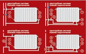
Types of bypasses used in one-pipe and two-pipe systems
Depending on the systems in which it will be used (one-pipe or two-pipe), the bypass can be divided into two types:
- Automatic (uses a check valve);
- Manual (no check valve).
Automatic bypass
An automatic bypass operates on the principle that heated water in an open tap moves along the path of least resistance, enters the bypass and, without gaining access to the radiator, returns in the opposite direction.
Due to this, the radiator batteries do not heat up excessively, and the coolant passes to the next element of the heating system. Automatic bypass is used to regulate the water supply and control the heating temperature of specific rooms. Such a device can carry out partial or complete removal of coolant from radiators. The circuit with a check valve is used in systems with forced circulation. In the event of a power outage, the pump will stop working, however, by shutting off the flow of water to it and opening the tap on the main pipeline, the natural circulation process can be started. The check valve is used as a constant source of circulation for the pump. It works offline and turns on as needed. An automatic bypass must be installed together with the pump.
Manual bypass
A circuit without a check valve is usually installed in multi-storey apartments. If it is necessary to repair the heating or replace the radiator, you need to turn off the tap running through the pipe. Such an action will lead to the fact that residents of the lower floors will be cut off from the source of coolant. It is in such cases that the device finds its practical purpose. A manual bypass allows you to install a bypass by disconnecting the main heating system from the batteries in the room. By turning off just two taps, you can turn off any heating elements. This function allows you to carry out any type of repair without compromising the integrity of the system. This explains the recommendations for installing a manual bypass in the heating system in apartment buildings.
Which bypass to choose
It is necessary to understand not only why a bypass is needed in a heating system, but also how to choose it correctly.
The main rule when choosing a bypass is the fact that the diameter of the bypass should be smaller by one size than the diameter of the pipes to which it will adjoin. The automatic option must be set if there are no impurities with solids inside the water system that could damage the valve itself. If the quality of the coolant is low, there is a possibility that the check valve will quickly wear out. Over time, it may begin to jam and turn poorly, which is why in such cases it is necessary to install specialized pumps for the diameter of the pipe with the function of protecting against scale and solid particles.
A single-pipe line uses a circuit with ball valves between the jumper itself and the battery. It also makes it possible to turn off individual devices. This calculation for the set diameter allows you to maintain water circulation through a parallel circuit.
Advantages of using an automatic bypass in a one-pipe and two-pipe system
In a one-pipe and two-pipe system using a bypass circuit, an overall increase in the heat transfer of batteries by 10-15% is observed. At the same time, the volumes of coolant supplied to the heating main are reduced by 30-35%. Proper calculation and installation of the bypass using a bypass can significantly increase the efficiency of the system and reduce utility bills.
Do-it-yourself bypass installation in the system
The automatic bypass should be installed closer to the radiator. The calculation must take into account the need to maintain a sufficient margin of distance from the riser. If necessary, additional taps are installed that can ensure water circulation through the radiator. In such a system where the bypass operates, there is an additional opportunity to regulate the temperature of the hot water.
There are no significant difficulties in installing such a structure with your own hands. Correct installation of the device occurs in the direction of the coolant:
- First, the filters are installed, then the check valve and circulation pump are installed;
- The bypass must be introduced into the riser using shut-off valves. Installation should be done in a horizontal position, since this eliminates the possibility of air accumulation in the system pipes;
- An additional tap should be made and installed on the jumper, which allows you to correctly regulate the heat flow through the bypass diameter. In this case, liquid will flow through the radiators and bypass pipe. An alternative scheme can use a special thermostat that will keep the temperature at the set mode.
Important! Ball valves are made from a housing shell and a metal ball in which a hole with a small diameter is made. Even if the valves are not used regularly, they should still be turned periodically, as they can become sticky if used infrequently. Such valves cannot be repaired, and if they fail, re-installation will be necessary.
How to choose a safety valve
The main criterion for choosing a safety device is the technical parameters of the heating system specified in the design documentation.
Most modern closed heating systems use standard direct acting brass safety valves.
They are suitable for installation in systems operating on diesel, gas or electric boilers. When a critical temperature and pressure is reached, the safety valve almost instantly stops further heating of the working environment and prevents an accident.
Simple brass safety valves are designed to exceed the pressure of the working medium up to 3-6 bar.
When choosing a valve for diesel, gas and electric boilers, you need to select safety devices that can withstand pressure 20-25% higher than the normal operating pressure in the system.
For solid fuel boilers operating on peat, briquettes or coal, you need to choose the type of waste dumps more carefully, because solid fuel cannot stop burning instantly and continues to heat water for some time after switching off.
They are suitable for modern thermal relief valves with a maximum operating pressure of 10 bar. The same applies to solid fuel boilers in open heating systems, in which relief valves work most effectively by responding to an increase in operating temperature rather than pressure.
It is not advisable to choose cheap engineering equipment from Chinese manufacturers: it is usually not of high quality and quickly breaks down. An indicator of wear is an increase in the number of valve operations.
We recommend that you read: Why do you need a check valve for water and how to install it correctly?
Clamping mechanism
Lever-load safety valves are designed for heavy loads and a pipe diameter of at least 200 mm, therefore they are used in industrial heating systems.
For individual heating of a private house, it is better to purchase a device with a spring mechanism; this is a standard, reliable and frequently used type of relief valve.
Lifting height
Pressure relief valves have different valve lift heights:
- Low-lift model PS-350. Low-lift. The height of the shutter in low-lift valves does not exceed 1/20 of the seat diameter. They have a relatively low throughput and a simple design. Used in lines with liquid coolant. As a rule, low-lift safety valves are sufficient for a heating system with a water circuit with a power of up to 40-43 kW. To prevent an accident in such systems, it is necessary to discharge a small volume of coolant.
- Full lift. The height of the valve in full-lift valves is greater than or equal to the diameter of the seat. As a rule, these are lever-load mechanisms, more expensive and complex in design. Full-lift valves have a high capacity and can be installed on lines in which gases, steam or compressed air circulate.
Full lift model PN 16.
Mechanism response speed
Based on response speed, safety valves are divided into proportional and on-off.
In heating systems of a private home, it is better to use proportional valves; again, they are sufficient for most systems. The shutter cover of such devices opens gradually, in proportion to the increase in pressure in the line, and accordingly, the volume of coolant discharged increases proportionally. Such valves do not self-oscillate, they maintain the correct pressure level and are cheaper.
Two-position safety valves are distinguished by instantaneous detonation and full opening of the valve. This mechanism allows you to quickly release large volumes of coolant, but creates the risk of water hammer: due to the rapid release of a large amount of coolant liquid, the pressure in the line significantly decreases, after which the valve closes sharply. Therefore, it is recommended to install two-position safety valves on lines with a compressible medium (air, gas, steam).
Diameter
The diameter of the pressure relief valve in the heating system should not be less than the connector of the supply pipe. Otherwise, the constant hydraulic pressure will interfere with the operation of the mechanism.
Manufacturer
Since safety valves have a fairly simple design, and modern models are in most cases made of brass using the same technology, there are no critical differences between valves from different manufacturers.
Safety relief valve: operating principle, applications and installation
A safety relief valve is one of the types of pipeline fittings that is designed to protect pipes from high pressure, regardless of the reasons for its formation. How to choose the right element of pipeline fittings? What aspects do you need to pay special attention to when choosing? How to install a safety valve yourself? Read on.
Fittings to protect the pipeline from excess pressure
Valve design and operating principle
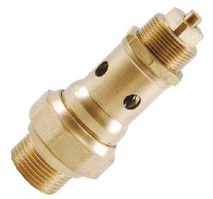
The safety relief valve (PSV) consists of the following elements:
- the device body, which is made of brass, bronze or other materials inert to corrosion and passing media;
- a membrane that, under excess pressure, acts on a spring, opening the passage;
- housing covers, rods and other additional elements that ensure correct operation of the main mechanism;
- two branches, one of which is intended to connect to the main branch of the pipeline, and the second to the emergency branch, into which the working fluid will be discharged, if necessary.
Main operating elements of a safety valve
The operating principle of the safety valve and the design of the fittings are presented in the video.
How to choose a safety valve
When choosing a UCS, you should consider:
- design features of valves;
- throughput;
- dimensions and technical characteristics of pipeline fittings.
Basic designs of PSK and their advantages
Depending on the design features, all safety valves are divided into two types:
- spring mechanisms. The design of valves of this type is the simplest, which helps to increase the service life of the valves. The valve is based on a spring, which is activated when the pressure in the heating system (gas or water supply) increases. The spring valve must be supplemented with a specialized device for forced operation, which eliminates the possibility of “sticking” of the shut-off valve assembly;
Safety valve with operating mechanism in the form of a spring
- membrane mechanisms. Unlike the previous type, fittings of this type are additionally equipped with a membrane, which is a sensitive part. The membrane signals the presence of increased pressure on the spring and only after this the valve opens.
PSK with an additional sensitive element
Types of valves by capacity
Valves are divided according to their capacity:
- for low lifting mechanisms. The throughput increases in proportion to the increase in pressure in the system. Typically this happens slowly over a period of time. The lowering of the shut-off element after an emergency operation is also slow, which reduces the tightness of the system. For this reason, it is not recommended to install low-lift valves on the gas pipeline;
- for full lifting mechanisms. Unlike the previous type, the valve operates abruptly, immediately when a critical pressure level is reached. The valve closes just as abruptly after the accounting indicator has normalized.
Dimensions and characteristics of fittings
When determining the main parameters of a safety valve, it is necessary to take into account:
- diameter (nominal diameter of the fittings) and overall dimensions;
- type of device connection (flange or coupling);
- tightness class (GOST 9544-2005);
- possibility of customization and its range (tuning is one of the most important selection parameters and depends on the technical data of the pipeline);
- controlled pressure parameters.
The main types of PSC are devices with a diameter of 25 mm and 50 mm. Technical characteristics of the fittings are given in the table.

Technical characteristics of PSK 25 and PSK 50
After selecting the valves, the operation of the device is checked and only after that the fittings can be purchased and installed.
Installation of safety valves
Installation of the PSK is carried out:
- threaded method, if coupling fittings were purchased;
Fittings for threaded installation
- on flanges (flanged fittings).
Flange fittings
When carrying out installation work, the following rules must be observed:
- It is recommended to install a pressure gauge near the PSK to control the pressure;
- The fittings are installed with the cap facing up. In this case, the liquid outlet pipes should be located vertically downward (into the sewerage system), and the pipes of steam systems and gas supply systems should be located upward;
Correct placement of the valve on the pipeline
- The direction of flow of the passing medium on the valve is indicated by arrows. Installation of fittings in a different position is not permissible;
- Shut-off valves of any kind must not be installed between the valve and the water/gas supply. Shut-off valves are also not installed on discharge pipes;
- before installing the equipment, it is necessary to clean all adjacent pipes from dust, dirt, rust and other deposits;
- installation and maintenance work on PSK, especially on gas pipelines, must be carried out by professionals.
After completing all work on installing the safety valve, the equipment is adjusted in accordance with the parameters of the pipeline system.
Operating principle
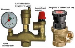
The safety valve in the heating system is included in the safety group
The main element of the valve is a steel spring. Due to its own elasticity, it controls the pressure on the only membrane that obscures the external outlet. The membrane is located in the saddle and is supported by a spring, the outermost part of which rests on a metal washer. It is securely fixed on the rod and attached to a plastic lever.
The safety valve for heating operates as follows:
- Under normal conditions, the membrane is in the seat and completely blocks the passage.
- As soon as the coolant overheats, it begins to expand, creating increased pressure in a closed hydraulic system. The latter is often compensated for by an expansion tank.
- If the amount of water pressure increases to the valve response value (most often 3 Bar), the spring is compressed and the membrane opens the passage. The boiling coolant is automatically discharged until the spring closes the passage hole.
- In the event of a breakdown, excess pressure can be released manually. Then turn the handle at the top of the safety mechanism.
The discharge mechanism is installed on the main section not far from the heating unit. The recommended distance is 0.5 m.
Breakdowns, causes, elimination
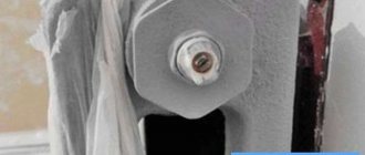
In principle, the safety valve for a water heater has only two failures: water either often flows from it or does not flow at all.
First of all, it must be said that bleeding of water when heating is the norm. This is how the system is supposed to work. Water may also be released when the boiler is turned off, if the pressure in the cold water supply pipes is higher than the valve response limit. For example, the valve is 6 bar, and the water supply is 7 bar. Until the pressure drops, the water will be released. If this situation repeats often, it is necessary to install a reducer, and it is best to use water in an apartment or house, but there are compact models of reducers that can be installed at the entrance to the boiler.
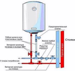
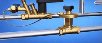
Boiler piping with safety valve and reducer
How to check the serviceability of the valve? If there is an emergency reset lever, this is easy to do. With the boiler turned off, you need to lift the lever several times to release excess pressure. After this, the dripping stops and does not resume until heating begins.
If water continues to drain, the spring may be clogged. If the model is serviceable, the device is disassembled, cleaned, and then put back in place. If the model is not collapsible, you just need to buy a new valve and install it.
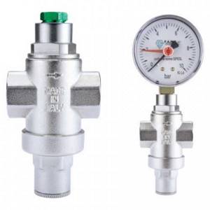
This is what the reducer looks like - to stabilize the pressure on the boiler
Constantly dripping water is unpleasant and hurts your wallet, but not dangerous. It is much worse if, when heating the water, you never see water in the pipe. The reason is that the valve is clogged or the outlet fitting is clogged. Check both options. If it doesn’t help, change the valve.