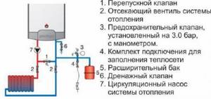
Types and designs
The device is available in the form of indirect and direct action mechanics.
The direct machine has a simple internal design. The damper operates from coolant pressure. The device is used due to its ease of use, insensitivity to contamination and reliability. Automation is characterized by reduced accuracy when setting nominal parameters.
The indirect-acting automation contains a pressure sensor and two valves:
- main, moving from a piston drive;
- pulse, having a small diameter.
When the pressure in the line decreases, the smaller valve puts pressure on the piston, causing the main damper to move. The throughput of the automatic device is regulated by an indirect method. The valves are adjusted more accurately, but are unreliable due to the many operating elements.
The systems use different heating devices. Each type requires a different design of overflow valve:
- A direct valve is installed in electrical systems running on diesel or gas.
- Solid fuel units do not turn off quickly, and smooth adjustment is not possible. Valves are used that respond to changes in the temperature of the energy carrier and an increase in pressure. The automation is connected to the cold pipeline and external sewage system.
- The adjusting handle is used in homes where the owner can independently set the permissible pressure.
- The autovalve is not used in open pipelines. The expansion tank regulates the pressure in the network by compensation.
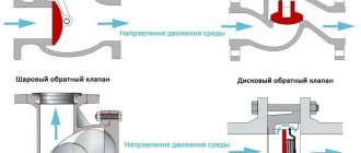
Direct and indirect acting valve
Pressure control valves are divided into direct and indirect acting devices.
- The first type of valve has a simple design: a spring is driven by a shutter, which is directly pressed by the coolant. Such devices are inexpensive, easy to operate, reliable, insensitive to dirt, but not very accurate in settings.
- Indirect-acting devices, also called pulse devices, have a piston-actuated main valve, a smaller pulse valve, and a pressure transducer. When the pressure changes, the small valve presses on the piston, which moves the main valve, which regulates the throughput of the device. Thus, flow control occurs indirectly, in an indirect way. Valves of this type are less reliable due to the larger number of parts and are expensive, but they can be adjusted more accurately.
Causes and Effects
Often, an increase in the pressure level in such systems is associated with the normal functioning of thermal valves that are installed on radiators or a thermal head. When the maximum temperature set in manual mode is reached, the supply of hot coolant to one or another radiator is reduced, which ensures an increase in pressure, and in some cases even the whistle of the radiator shut-off valves.
Of course, this affects, in addition to the level of comfort in the room, also the performance and durability of the heating system and its individual components. To avoid such situations, professionals recommend equipping heating systems with thermostatic valves.
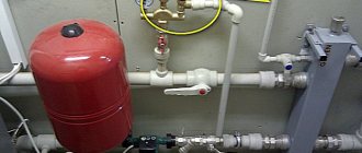
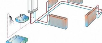
Where to mount and why
The thermostatic valve is mounted by inserting it into the system at a short distance from the liquid supply pump, between the return and supply circuit. The mode for setting the maximum permissible pressure limit of the working medium allows the owner to make the settings manually.
Currently, the range of these products offered by the retail chain is quite large. But as practice shows, it is better to pay attention to such well-known brands as Mankenberg, Valtec, DANFOSS. They have proven in practice efficiency, reliability and durability in operation.
Purpose
Regulating thermostatic bypass valves are designed to ensure a stable pressure difference between the return and supply pipelines in closed heating systems. When the heat load decreases, the thermostatic radiator valves close. This leads to an increase in the pressure drop between the return and supply pipelines.
Using a bypass valve offers the following advantages:
- reduces the load on the pump;
- protects the boiler from rust;
- prevents the occurrence of noise unnatural for normal operation;
- increases the temperature of the working medium in the return pipeline.
By closing the thermostatic valves on the radiators, we will increase the resistance of our heating system (increase in the pressure difference between the return and supply pipelines). This will increase the load on the pump and lead to noise.
If the pressure reaches the maximum level, which corresponds to the settings of the bypass valve, it opens, forming an adjustable bypass. Also, a bypass valve is installed behind the circulation pump between the return and supply pipelines.
Types of valves
You can select a manual, fixed or automatic bypass valve for installation. All types have their own characteristics; installation depends on the insertion location, additional devices in the system and their type.
Unregulated bypasses
The device is a section of a bypass pipe without additional shut-off elements. The tunnel is open all the time, water circulates constantly. Unregulated devices are used to connect radiators.
When the valve is in a vertical position, the cross-section of the bypass pipe should be smaller than the cross-section of the internal tunnel of the main pipeline, so that under gravity the water does not flow into the adjacent bypass channel. In a horizontal position, the cross-section of the bypass and main pipes is the same, but the pipe to the radiator is selected smaller than the bypass device and the main.
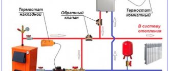
Weather thermostat for heating boiler control
Manual or mechanical bypass
In contrast to the non-adjustable bypass section, the manual bypass valve is complemented by a ball valve. In the open state, the internal tunnel of the pipe is completely open and the liquid is not retained; there is no additional hydraulic resistance to the flow. When the valve is closed, the coolant flows only into the main pipeline.
A manual bypass valve helps to quickly shut off the coolant if this is necessary for repair work or adjusting the intensity of heated water circulation. To prevent the ball valve from silting or sticking, it must be turned regularly.
Automatic bypasses
A heating system bypass valve is installed when connecting pumping equipment to systems with gravity or forced circulation. The device operates without human intervention; the flow direction is adjusted automatically. While the pump continues to operate, the coolant flows through the device; as soon as the pump is turned off, water flows through the bypass tunnel. This is necessary to bypass the pump impeller, lowered into the main tunnel - the equipment helps the coolant circulate without interference.
Automatic bypass valves can be of two types:
- Valve They are installed with a ball valve, which reduces the hydraulic pressure on the coolant water. A simple and reliable device is sensitive to water purity; mechanical particles and solid suspensions in the flow quickly cause the equipment to fail.
- Injection. The operating principle is similar to a hydraulic elevator. The pump unit is installed on a section of the main line; the inlet and outlet pipes of the bypass valve are continued inside the pipe. When transporting water, a vacuum area is formed behind the outlet pipe, and water is drawn in from the bypass. Then the flow under pressure passes into the pipeline - this scheme eliminates the possibility of reverse flow of water. When the pump is turned off, water flows through the bypass device by gravity.
Installation features
The specific installation location of the bypass device depends on the layout and type of pipeline. The valve can be integrated into an additional diverter circuit. For closed-cycle heating systems, excess pressure is released into the return pipeline. It can also be used as a safety valve, adjusted to emergency pressure and with liquid discharge into the sewer system.
In a single-circuit heating main circuit, the bypass valve is installed in the bypass outlet after the injection pump.
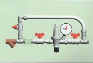
Bypass valve for local heating system. Installation diagram.
For greater safety and security of the entire heating circuit, it is advisable to install additional ones in addition to the bypass device:
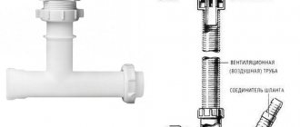
- check valve to prevent reverse flow direction,
- air vent valve for bleeding air pockets,
- drain valve to completely drain the media from the system,
- for small-diameter cottage-type systems - mesh filters.
In multi-circuit systems, bypass valves are installed in each circuit.
Flow regulator
Having installed energy metering devices, the question naturally arises of how you can regulate and control the supply of coolant, limit or add its flow. For this purpose, there are all kinds of automatic regulators, the use of which allows you to save money; they operate from outside air temperature sensors and return pipeline sensors. Another advantage of temperature controllers is that they control the temperature directly at the radiator installation site, unlike other devices. This advantage gives priority in obtaining a uniform temperature background for a comfortable stay in the room. The regulator will prevent overheating of the air in the room, which sensors on centralized automation cannot always track. It is possible to adjust the temperature for each room separately. Sometimes, when solving the adjustment issue, ordinary taps are installed. Of course, this solution reduces financial costs, but deprives a number of useful advantages. The faucet has limited functionality to open and close. There is a danger of stopping or airing the riser. By adjusting the heating using taps it is impossible to achieve the required temperature. Using automatic regulators, you can adjust the system accurately and efficiently.
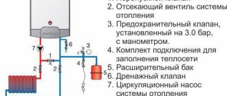
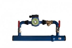
Operating principle of the heating system bypass valve
The bypass valve is connected to:
p, blockquote 4,0,1,0,0 —>
- pump;
- return pipe;
- supply pipe.
The operating principle of the heating system bypass valve differs from the safety valve, so they should not be identified. They are connected in different ways, the safety one is mounted to the waste pipe.
p, blockquote 5,0,0,0,0 —>
When the radiators are closed under the influence of thermostats, the pressure in the heating system increases and the bypass valve is turned on, which transfers the hot liquid to the return line.
The rapid operation of the bypass valve also reduces the pressure in the heating circuit and makes it more stable, which significantly reduces the risks for water radiators.
p, blockquote 7,0,0,0,0 —>
If we are talking about more complex heating systems, where there are several circuits, then in such cases the bypass valve is mounted behind all circulation pumps that are present in the system. If bypass valves are installed in such systems, the heating circuits operate stably and without failures in normal mode.
p, blockquote 8,1,0,0,0 —>
In heating systems, the circulation pump is followed by a check valve, which acts as a kind of obstacle to the coolant and does not allow it to move in the opposite direction due to increased pressure.
The design of the check valve consists of a damper and a spring with a small force, which is quite enough to block the passage for the coolant, the movement of which can go in the opposite direction.
p, blockquote 10,0,0,0,0 —>
Air and its release from the heating system
Air congestion is a fairly common occurrence, but an unpleasant one. Characteristics that indicate that there is air in the radiator and bleeding is required:
- presence of noise during operation;
- corrosion.
Pressure plays an important role in any system. There are a number of reasons that can affect pressure changes. One of the most common reasons for an increase in pressure is the formation of an air lock.
Air may appear in the system and require bleeding due to several factors:
- the presence of dissolved air in the water, which, when heated, accumulates in the upper part of the pipe;
- accidental air release during installation;
- when filling the system with water, they did not adhere to certain rules: slowly filling the pipes with coolant;
- air could be sucked in through poor sealing at the joints of the structure.
The heating system air bleed valve is an important and mandatory element in every design. The best way to eliminate air is a multi-stage deaeration system. Air drain elements are installed not in one place, but in several. If started correctly, the air bleeding stage will not be difficult.
The air bleed element is:
- manual;
- auto.
The presence of several drain valves does not imply their simultaneous opening. If this is a multi-story building, then all the air will accumulate in one place and, due to pressure, go to the neighbor. When the bleeder valve opens, a hissing sound is heard, which means that air is escaping from the radiator.
The drain valve must not be opened completely and one at a time
It is important to carry out the air descent slowly, gradually. After a hissing sound, water will begin to drip from the drain valve.
It is important to continue and open the drain element until the water does not drip, but flows in a trickle. This means that the air has escaped.
How is the heating system automatic make-up valve used?
Since the main coolant in heating systems is water, during operation the liquid gradually loses its volume, that is, its quantity decreases.
When coolant volumes reach a critical value, the balance of the heating system is disrupted.
To prevent such deviations in the operation of heating circuits, a special valve is used that normalizes the operating pressure and ensures stability.
The operation of the heating system becomes more controlled and balanced if an automatic replenishment valve for the heating system is installed. After all, constantly using the valve to normalize the pressure in the heating system is too labor-intensive, and the user simply forgets about such types of adjustment, so it would be preferable to install an automatic make-up valve.
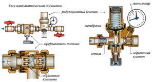
In addition, when using a valve, there is a real risk of increasing differentiated pressure, which will lead to an emergency and damage the heating equipment. And another negative phenomenon when using a manual increase in coolant supply is air bubbles that leak into the heating system. Thanks to the automatic heating system make-up valve:
- The pressure in the circuits is constantly monitored,
- The coolant enters the system in portions, without placing additional load on the heat exchanger,
- No air leaks into the system.
The heating system design must include not only heating equipment, but also additional elements that can ensure uninterrupted and stable operation.
More on this topic on our website:
- I choose floor heating radiators - water with a fan
- The floor design of heating equipment has its own subtleties, as well as a number of negative and positive aspects, which you should learn about in more detail.
Inverter for heating boiler - which one to choose, pros and cons
Electrical energy is actively used during the operation of the heating system; it is thanks to it that the coolant receives the required temperature and distributes it through the pipelines. Developments aimed at significantly increasing productivity.
Safety valve in the heating system - why and how to install it
- Due to constant changes in coolant temperature in heating circuits, an involuntary increase in the volume of water in the system occurs, and a special valve will provide reliable protection against this phenomenon. Let's try.
How to choose an electric boiler for heating your home
- Definitely, starting with simple words, we can say something like this - an electric boiler is extremely necessary today. The reason, which is also an explanation, is very simple and lies in.
Add a comment Cancel reply
You can subscribe to new publications by email.
The bypass valve of the heating system thermostat is a fairly simple mechanism that is used to relieve the working environment. The thing is that heating devices, which include a thermostat, constantly work in new conditions, since they instantly respond to any, even the most minor changes in the environment.
Types and designs
According to the operating principles, bypass valves are distinguished with spring and membrane designs. Spring mechanisms prevail in systems where the pipeline cross-section is no more than 200 mm; in other water supply and heating networks, the lever-load principle is used.
Membrane units are increasingly used when working with liquid media that contain solid particles.
Depending on the pipeline environment, bypass devices are intended for:
- gas;
- pair;
- liquids.
According to the purpose of the system, they are used for pipelines:
- cold water supply,
- hot water supply,
- heating,
- cooling,
- conditioning.
In heating and water supply systems, bypass valves are distinguished according to their purpose:
- for radiators;
- for boiler and bypass;
- for automatic replenishment;
- for low or high pressures.

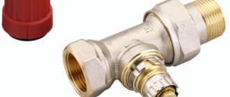
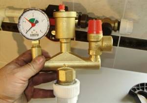
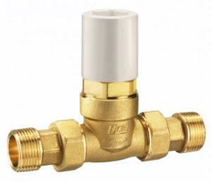
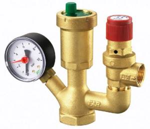
This photo shows an overflow valve with a setting scale. Made of bronze and brass, designed for installation in central heating systems.
Along with bypass regulators, the following is installed in the heating design:
- air vent to prevent air locks in pipes;
- three-way valve for mixing or separating hot and cold water flows;
- reverse, preventing backflow in the pipeline.
For industrial and utility networks, designs with a nominal diameter DN of up to 500 mm and a flange connection are used.
In the car there are access devices for:
- turbines;
- fuel supply mechanism;
- engine cooling systems.
The turbine bypass unit discharges the exhaust gases, reducing the pressure force in the manifold. Thus, it protects the engine from overheating.
How to choose a valve for a boiler and bypass
In the factory configuration, boilers and bypasses are either equipped with the simplest bypass valve or do not have a device for redirecting the flow.
In the first case, you can not interfere with the design of the water heater or bypass element and install them in their existing form.
In the second case, it is necessary to purchase and install bypass valves. A bypass without this device will only allow the flow of the working medium to pass when the heating circuit is turned off, but will not be able to regulate the pressure. A boiler that is not equipped with a bypass valve is susceptible to overheating and may break down, since the water in it will boil and turn into steam, further increasing the pressure on the pipes and the heating unit itself.
The choice of device depends on the heating or water heating device: the fuel it uses, the maximum permissible pressure specified in the technical documentation.
Note! It is also important to consider your own capabilities to manage the pressure regulation process - whether you have the skills to configure the operating parameters of the bypass valve.
The price of the product in this matter can only play a role when choosing between similar devices from different manufacturers.
We recommend that you read: How to calculate and make a staircase from a profile pipe in a private house?
Different types of heating devices require valves of different designs:
- Systems running on electricity, gas or diesel fuel are undemanding - to regulate the pressure in them, a simple bypass valve that does not have additional elements is sufficient.
- Solid fuel does not stop burning immediately, therefore it is impossible to immediately turn off the solid fuel boiler or smoothly adjust the heating temperature. Therefore, in solid fuel heating systems it is important not only to regulate the pressure, but also to cool the heat-generating unit. Bypass valves are installed on bypasses and boilers, which respond to both an increase in pressure and an increase in the temperature of the coolant. Such devices are equipped with a temperature sensor, a coolant discharge and replenishment system and are connected to a sewerage system and a cold water supply system.
- A bypass valve with a control handle should only be installed if the homeowner already knows how to set the pressure limit. If you try to acquire this skill in practice, you can break the device, cause an accident, or get burned.
- For open-type thermal circuits, bypass valves are not required - the compensation tank copes with the task of regulating pressure without them.
- The technical characteristics of the bypass valve must correspond to the parameters of the heat source: the control valves must be set to the same maximum pressure as the heat-generating device and have a flow capacity no lower. It is also important to match the dimensions of the connecting pipes - if this condition is not met, you will have to use fittings for connection, which will make the system more vulnerable.
Specifications
Each bypass valve is characterized by several parameters, which should also be taken into account when choosing a product:
| Characteristic name | What does it mean |
| throughput | volume of coolant consumed per unit time at unit pressure |
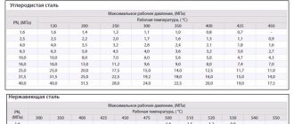
| nominal pressure | maximum excess pressure of the working environment, maintained at 200 degrees |
| nominal diameter | the internal cross-section of the connecting pipes may have a slight deviation from the actual size |
| setting range | limits of the maximum pressure adjustable on the valve |
What is the purpose of a bypass valve in a pipeline?
During operation of heating or water heating systems, the volume of the working medium may change. An increase or decrease in coolant pressure negatively affects the performance of the heating circuit: it can lead to uneven heating, airing of system components, and breakdowns. Changes in the pressure of the working environment also affect comfort: the temperature in the rooms changes uncontrollably, and the pipes begin to hum and vibrate
To prevent this from happening, it is important to maintain a pressure balance in the pipeline
It is not difficult to constantly monitor the pressure, bleed or add coolant manually, but it is better to entrust this routine work to automation.
There are several types of control valves that cope with this task better than a person.
The bypass, or overflow, valve allows you to stabilize the pressure in the pipeline by redirecting the working fluid through an additional branch of the pipeline, called a bypass.
Regulation does not occur by one-time or periodic bleeding of excess coolant, but in portions, due to which the pressure of the liquid or gas is constantly maintained at the same level.
The device can and should be equipped with pipelines of any complexity, but most of all they need pressure adjustment:
multi-circuit heating systems - if one of the circuits is turned off, coolant consumption decreases and pressure increases, which can cause pipeline breaks, overload the pump and heat-generating device - to avoid this, you need to reduce the pressure and maintain it at the required level; heating systems equipped with thermostats and hot water supply systems - when setting the temperature, the volume of coolant consumed changes, and it is necessary to quickly restore the pressure balance in the circuit; water supply systems equipped with storage-type water heaters - in the boiler and pipeline the water is under high pressure, and since the volume of supplied liquid changes jerkily due to constant adjustment and frequent turning on and off of water, it is especially important to regulate the pressure of the working medium so that an accident does not occur and The water heater is broken.
This is interesting: Technical characteristics and scope of use of reinforced pipe insulation (video)
Difference from other control devices
A bypass valve is often confused with a safety valve and a pressure relief valve. However, despite the general similarity in appearance and functions performed by these devices, there are differences in the mechanism of pressure reduction and the frequency of action.
| Device type | Pressure reduction mechanism | Frequency of action |
| bypass valve | excess working medium is diverted into an additional branch of the pipeline, the pressure of the liquid or gas passing through the main branch is regulated, while the valve is located on the additional | constantly as long as necessary |
| safety valve | excess coolant is released into the external environment or sewerage by opening the valve | occasionally due to pressure changes |
| pressure reducing valve (pressure reducer) | installed on the main branch and regulates the pressure of the working medium by decreasing and increasing its throughput, controls the pressure in the part of the pipeline located after the device | constantly |
We recommend that you familiarize yourself with: Types and functional features of a flanged check valve
What is it and why is it needed?
The volume of coolant changes during operation. A change in pressure impairs the performance of the heating main. The pipes heat up unevenly, air accumulates in certain areas, and components become unusable. The pressure balance is maintained manually, but it is better to entrust the change in the amount of fuel to automation, which requires a valve in the system.
Device specifications:
- DN is the nominal diameter of the connection pipes. The value is used in the case of standardization of standard sizes of collector fittings. Actual DN may vary slightly upward or downward. A similar characteristic was used in the post-Soviet period to indicate the diameter of the nominal bore - Dn.
- PN is the nominal pressure of liquid or gas at a temperature of +20°C. The pressure increase in the system remains within standard limits, ensuring operational safety. The characteristic was used in a similar designation Ru automation in the post-Soviet period.
- Kvs is the coefficient of ability to pass a volume of liquid when the coolant is heated to +20°C. The reduction in pressure in the automation shows 1 bar. The coefficient is used in calculations of hydraulic systems to identify pressure losses.
- Setting range is the difference in pressure change maintained by the automatic device. The indicator depends on the degree of elasticity of the spring.
Specifications
The main quantities that determine the operation capabilities of bypass devices in the system:
- Passage diameter. Internal cross-section of the carrier passage through the valve. May differ from the diameter of the main circuit of the system.
- Bandwidth. Characterizes the volume of the working medium capable of passing through the valve per unit time at a nominal pressure of 1 atm. Measured in cubic meters/hour.
- Ultimate pressure. The maximum value of excess pressure for which the device is designed to operate. Exceeding this parameter in the system leads to displacement of the valve rod and the beginning of media bypass. Determined at a carrier temperature of 20 °C.
- Setting range. The limits of the possibility of adjusting the excess pressure at which the valve begins to open. The unit of measurement is bar.
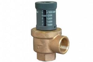
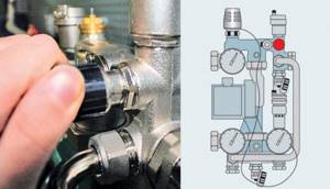
Adjustment scale with tuning slider
What is a bypass in a heating system?
A bypass is a section of pipe installed so that a path is opened for the coolant not only through one device, but also bypassing a certain section of the heating main, as well as parallel to the main pipeline. Often, equipment is installed in the bypass section, one end of which is connected to the inlet pipe, and the other is fed to the outlet pipe.
The section is also equipped with shut-off valves to shut off the flow of coolant through the bypass section and regulate the flow of liquid to the device. In order to be able to disconnect the equipment from the coolant supply, it is recommended to install a valve on the outlet pipe - the installation area of the valve is located between the bypass valve and the outlet of the boiler, radiator, central riser or other device.
A bypass is used in the heating system in the following cases:
- when piping radiators, most often in single-pipe circuits;
- for autonomous heat supply systems when piping pumping equipment;
- for circuits in heated floors in the area of the mixing unit;
- when creating a small circulation circuit for piping solid fuel boilers.
How to know if your heating system needs a bypass valve
For all valves installed in heating systems, careful calculations must be carried out, and the hydraulic resistance is taken as a basis, as well as the pressure in certain sections of the heating circuits.
Each check valve has its own hydraulic resistance, and it must be taken into account when performing calculations - this will help when choosing a pump for the heating circuit. If all necessary calculations are carried out before installing the heating system, based on their results the following will be purchased:
- water radiators,
- pipelines,
- circulation pumps,
- heating boilers,
- water fittings,
- various types of valves.
Selection tips and approximate prices
When choosing a bypass device, the consumer must be aware that it is designed to ensure normal operation of the system and constantly maintain stable pressure inside it.
Such a device must meet the following requirements:
- help reduce pressure, quickly redirect excess coolant volume to another circuit;
- have a sufficient range of adjustment;
- be suitable for the method of connection to pipes, for example, have a threaded connection for pipes with a diameter of ½′′.
The throughput device is selected, first of all, based on the type of working medium of the pipeline: gas, steam, water.
Next, they are guided by certain criteria.
Correct selection and replacement of the injection pump bypass valve
Reducing valves have an extremely simple design, but they are constantly subjected to high loads and quite often fail. Valve malfunction is manifested by deterioration of engine performance - it loses throttle response and in some modes there is a noticeable deterioration in its performance. In these cases, it is necessary to dismantle and check the valve, and, if it is faulty, replace it.
To replace, it is necessary to select a bypass valve of the same type and model that is installed on the injection pump by the manufacturer - only in this case there is a guarantee that the valve has the necessary characteristics and will ensure normal operation of the pump. Many valves allow adjustment of the pressure at which fuel is bypassed - this adjustment must be made in strict accordance with the instructions for maintenance and repair of the car/tractor. As a rule, adjustment comes down to changing the number of washers placed under the valve head, although there are exceptions - it all depends on the specific type of device.
With the correct selection, replacement and adjustment of the pressure reducing valve, the fuel pump will operate effectively in all modes, ensuring normal operating characteristics of the power unit.