When installing heating systems, a wide range of fittings are used to protect the heating boiler, ventilate the circuit, drain and pump coolant into the pipeline and a number of other functions. One of the devices that is not so often used when installing a main line is a heating system check valve, used in specific situations.
It is worth noting that the valve is optional in the heating circuit and is installed as an auxiliary device in the case of a certain operating mode of pumps and heating boilers. To ensure the need for use and make the right choice of valve, you should consider specific cases of its operation and the types of devices offered in the retail chain.
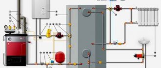
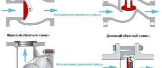
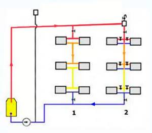
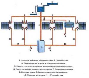
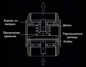
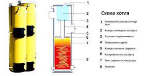
Rice. 1 Valve valves in a line with two boilers
Why is forced circulation needed?
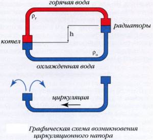
Natural circulation of the coolant occurs according to physical laws: heated water or antifreeze rises to the top point of the system and, gradually cooling, falls down, returning to the boiler.
For successful circulation, it is necessary to strictly maintain the angle of inclination of the forward and return pipes. With a short system length in a one-story house, this is not difficult to do, and the height difference will be small. For large houses, as well as multi-storey buildings. Such a system is most often unsuitable - it can cause air pockets to form, circulation to be disrupted and, as a result, the coolant in the boiler to overheat. This situation is dangerous and can cause damage to system components.
Therefore, a circulation pump is installed in the return pipe, immediately before entering the boiler heat exchanger, which creates the required pressure and water circulation rate in the system. At the same time, the heated coolant is promptly discharged to the heating devices, the boiler operates normally, and the microclimate in the house remains stable.
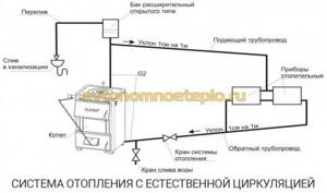
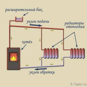
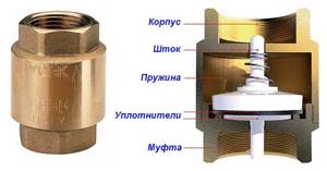
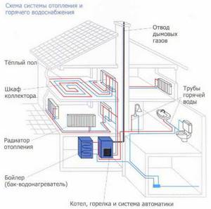
Diagram: heating system elements
- the system operates stably in buildings of any length and number of floors;
- you can use pipes of smaller diameter than with natural circulation, which saves the cost of purchasing them;
- it is allowed to place pipes without a slope and lay them hidden in the floor;
- Warm water floors can be connected to the forced heating system;
- stable temperature conditions extend the service life of fittings, pipes and radiators;
- It is possible to regulate the heating for each room.
Disadvantages of a forced circulation system:
- it requires calculation and installation of the pump, connecting it to the electrical network, which makes the system energy-dependent;
- The pump makes noise when operating.
The disadvantages are successfully solved by correct placement of the equipment: the pump is placed in a separate room of the boiler room next to the heating boiler and a backup power source is installed - a battery or a generator.
Heating safety valves
In addition to the heating bypass valve, the normal operation of the system requires the installation of other types of control and safety valves. During heating operation, excess air may appear and the coolant will move back. To prevent these phenomena, it is necessary to provide in advance the installation of an air valve for heating and return.
Types of safety valves
Depending on the functional purpose, there are two types of safety valves - to remove air from the system and to prevent the reverse movement of water in the pipes. Without these elements, the operation of the system may be unstable, which will lead to a violation of the temperature regime, destabilization of pressure and the creation of emergency situations.
- In places with the highest probability of excess pressure - after boilers, circulation pumps, on collectors;
- A heating ball valve or its petal equivalent must be mounted on the return pipe. It is also necessary to install this component in the circulation pump piping;
- At the highest point of the circuit - to remove air from the system. A Mayevsky tap is installed on radiators and batteries.
Safety valves must not impair the performance of the heating system. First of all, they eliminate possible malfunctions in the heat supply. In the “inactive” state, these system components should not impair the speed of movement of the coolant or affect the temperature regime.
Heating air valve
During heating operation, air pockets may form in pipes and radiators. The reason for this is the high oxygen content in the water and the coolant temperature above +100°C. As a result, oxidation of metal components occurs and the temperature distribution changes. To avoid these situations, it is necessary to install valves to bleed air from the heating system.
Working principle of the air valve
First of all, the air valve for heat supply is mounted in the safety group along with the drain and pressure gauge. In the heating circuit they are located on a straight branch leading from the boiler. This place has the highest coolant temperature, as well as maximum pressure. In the manifold circuit, it is mandatory to install heat supply drain valves on each comb.
- Mayevsky crane. Installed in the radiator (battery) and needed to remove air pockets;
- Automatic air vent. Mounted at the highest point of the system, as well as in security groups. Air from the heating system escapes through it.
For the latest model, it is important to comply with the operating conditions. After a long period of inactivity, there is a high probability that some moving components will “stick” and then the air vent will not work.
To avoid this, the structure should be regularly inspected and, if necessary, replaced with a new one.
Heating check valve
In gravity systems and in heating schemes without a circulation pump, there is always the possibility of a change in the direction of water movement. In this case, the boiler heat exchanger may be damaged due to overheating, as well as failure of other components. To prevent such situations, a check valve is installed.
Operating principle of a check valve
In large heating circuits, a heat supply ball valve is installed. Under the influence of the reverse flow of water, the polymer ball blocks the pipeline, thereby preventing the movement of the coolant. As soon as the direction changes, it falls down under the influence of gravity. The solenoid valve for the heating system works on the same principle. The difference lies in the control element - a solenoid or an electromagnetic coil is used for this.
The advantages of installing a solenoid valve in a heating system are as follows:
- Possibility of connection to the programmer;
- Setting the operation mode of the device depending on external factors - temperature or pressure;
- Reliability of operation.
The disadvantage of solenoid valves in heat supply is their dependence on the supply of electricity. In autonomous heating, a spring version of the check valve is used. The water pressure constantly acts on the saddle, compressing the spring. As soon as the direction changes, the movement of the coolant will be automatically blocked.
The principle of operation of a gravity heating system
The principle of heating operation looks simple: water moves through a pipeline, driven by hydrostatic pressure, which appears as a result of different masses of heated and cooled water. This design is also called gravity or gravity. Circulation is the movement of cooled and heavier liquid in the batteries under the pressure of its own mass down to the heating element, and the displacement of light heated water into the supply pipe. The system operates when the natural circulation boiler is located below the radiators.
In open-type circuits, it communicates directly with the external environment, and excess air escapes into the atmosphere. The volume of water that increased due to heating is eliminated, and the constant pressure is normalized.
Natural circulation is also possible in a closed heating system if it is equipped with an expansion tank with a membrane. Sometimes open-type structures are converted into closed ones. Closed circuits are more stable in operation, the coolant in them does not evaporate, but they are also independent of electricity. What affects circulation pressure
The circulation of water in the boiler depends on the difference in density of the hot and cold liquid and on the magnitude of the height difference between the boiler and the lowest radiator. These parameters are calculated before the installation of the heating circuit begins. Natural circulation occurs because The return temperature in the heating system is low. The coolant manages to cool down, moving through the radiators, becomes heavier and with its mass pushes the heated liquid out of the boiler, forcing it to move through the pipes.
Water circulation diagram in the boiler
The height of the battery level above the boiler increases the pressure, helping the water more easily overcome the resistance of the pipes. The higher the radiators are located in relation to the boiler, the greater the height of the cooled return column and the greater the pressure with which it pushes the heated water upward when it reaches the boiler.
Density also regulates pressure: the more the water warms up, the less its density becomes in comparison with the return. As a result, it is pushed out with more force and the pressure increases. For this reason, gravity heating structures are considered self-regulating, because if you change the heating temperature of the water, the pressure on the coolant will also change, and therefore its flow will change.
During installation, the boiler should be located at the very bottom, below all other elements, to ensure sufficient coolant pressure.
Pipes for natural circulation systems
When selecting the diameter of pipes, not only the size of the system and the number of radiators play a role, but also the material from which they are made, or rather, the smoothness of the walls. For gravitational systems this is a very important parameter. The situation is worse with ordinary metal pipes: the inner surface is rough, and after use it becomes even more uneven due to corrosion processes and accumulated deposits on the walls. Therefore, such pipes are taken of the largest diameter.
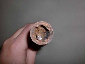
Steel pipes may look like this in a few years
From this point of view, metal-plastic and reinforced polypropylene are preferable. But metal-plastic fittings are used that significantly narrow the clearance, which can become critical for gravity flow systems. Therefore, reinforced polypropylene ones look more preferable. But they have restrictions on the coolant temperature: operating temperature is 70 o C, peak - 95 o C. Products made from special PPS plastic have an operating temperature of 95 o C, peak - up to 110 o C. So, depending on the boiler and the system as a whole, you can use these pipes, provided that these are high-quality branded products and not counterfeits. Read more about polypropylene pipes here.
Metal-plastic and polypropylene can also be used for installation of heating systems
But if you plan to install a solid fuel boiler. then no polypropylene will withstand such thermal loads. In this case, either use steel, or galvanized and stainless steel on threaded connections (do not use welding when installing stainless steel, since the seams leak very quickly)
Copper is also suitable (it is written about copper pipes here), but it also has its own characteristics and must be handled with care: it will not behave normally with all coolants, and it is better not to use it with aluminum radiators in the same system (they are quickly destroyed )
The peculiarity of systems with natural circulation is that they cannot be calculated due to the formation of turbulent flows that cannot be calculated. They are designed based on experience and averaged, empirically derived norms and rules. Basically the rules apply:
- raise the acceleration point as high as possible;
- do not narrow the supply pipes;
- supply a sufficient number of radiator sections.
Then they use another one: from the place of the first branch and each subsequent one they lead with a pipe of a smaller diameter step. For example, a 2-inch pipe comes from the boiler, then 1 ¾ from the first branch, then 1 ½, etc. The waste is collected from smaller to larger diameters.
There are several other features of installing gravity systems. First, it is advisable to make pipes at a slope of 1-5%, depending on the length of the pipeline. In principle, if there is a sufficient difference in temperature and altitude, it is possible to make horizontal wiring, the main thing is that there are no areas with a negative slope (inclined in the opposite direction), which, due to the formation of air pockets in them, will block the flow of water.
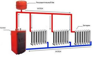
Gravity single-pipe system with vertical distribution into two wings (circuits)
The second feature is that at the highest point of the system you need to install an expansion tank and/or an air vent. The expansion tank can be an open type (the system will also be open) or a membrane type (closed). When installing an open vent, there is no need to vent air; it collects at the highest point - in the tank and goes out into the atmosphere. When installing a membrane type tank, the installation of an automatic air vent is also required. For horizontal wiring, “Mayevsky” taps on each of the radiators will not interfere - with their help it is easier to remove all air pockets in the branch.
Rules for choosing a locking device
Choosing a check valve intended for a heating system is a responsible undertaking. If knowledge in this area is minimal, it is best to seek help from specialists. This will ensure that your new heating system is functional and safe.
You need to know that, regardless of their type, all check valves differ in the way they are connected to the pipeline.
Sleeve check valves are very easy to install. However, the threaded connection cannot withstand high pressure, so they have limitations in use
Coupling devices are equipped with a connecting threaded unit, which greatly facilitates their connection to the main line. Most often, such a unit is equipped with disc valves intended for installation in autonomous heating systems of an apartment or private house. Their distinguishing feature is their small diameter. Most often it is no larger than DU-50.
Flange products are a structure assembled on the basis of a part that has holes for fastenings. Using the latter, it is connected to the main pipeline. A flange connection is much stronger than a threaded connection.
For this reason, flanged valves are widely used in the construction of large-diameter pipelines. Ball type devices are most in demand.
Wafer devices are designed for installation between two pipe flanges. They are lightweight and compact. Very often, both types of reed-type valves are produced in wafer design.
On sale you can find check valves that are installed by welding. This option can be used, for example, when installing heating from polypropylene pipes.
Flanged type check valves are securely attached to the pipe. This connection can withstand high pressure, which allows the devices to be used in centralized pipelines
Another important selection criterion is the material from which the device is made. It could be stainless steel. This option is considered optimal for highways with a diameter of less than 0.04 m.
The metal is practically not subject to corrosion processes and can withstand loads of up to 10 atm. This allows the valve to operate in the system trouble-free and for a very long time, but its cost is quite high. Brass valves have a lower price. They are subject to corrosion, but this process occurs very slowly, which significantly increases their service life.
However, their mechanical strength is much lower than that of stainless steel. Nevertheless, they can withstand the loads that arise in a household network quite easily. The most durable valves are made of cast iron - they successfully cope with critical pressure values, have significant dimensions and impressive weight.
Due to the nature of production, only body parts with a diameter greater than 40 mm can be made of cast iron. For this reason, they are used extremely rarely for the installation of autonomous heating systems.
It is desirable that not only the body, but also all internal elements of the check valve are made of metal. Plastic usually has less strength, which can lead to premature failure of the part.
When choosing a check valve, you need to remember one more rule - its diameter must exactly match the parameters of the through hole
It is very important that the operating pressure of the system does not exceed the maximum permissible values for operation established by the manufacturer of the selected model
Installation diagram of gravity heating systems
Since the circulation of water in the heating system occurs without the participation of a pump, for the smooth flow of liquid through the lines, they must have a diameter larger than in a scheme where water circulation is provided forcibly. The gravity system functions by reducing the resistance that water has to overcome: the further the pipe is from the boiler, the wider it is.
Water heating with natural circulation can have top or bottom wiring. When the wiring is designed as a two-pipe system, the heated water flows directly into each battery, rather than passing through them one by one, as in a single-pipe scheme.
The top distribution, in which the coolant first rises to the ceiling and from there goes down to the radiators, is best suited for installing such a structure. If the wiring is planned to be lower. then an accelerating circuit is constructed: a height difference at which water from the boiler first goes upward, where at the top point of the pipeline it enters the expansion tank, and then descends to the heating radiators.
The higher the heating device is located, the higher the pressure inside the pipeline. Therefore, radiators on upper floors often warm up better than those on lower floors. Accordingly, if you use two-pipe heating with natural circulation, the batteries placed at the same level as the boiler or below do not warm up enough.
To avoid such a situation, the boiler room is thoroughly buried, ensuring a sufficiently high pressure for the coolant to pass through the pipes at the required speed. The boiler is placed in the basement, approximately 3 meters below the center of the lowest heating element. Pipes with hot water, on the contrary, are raised as high as possible, placing an expansion tank at the highest point of the structure, and then the water from the supply pipe descends to the radiators.
Types of devices and areas of their application
The selection of the device is dictated by the conditions in which it will be used; it depends on the type of heating networks and their internal pressure. An incorrectly selected mechanism can itself cause emergency situations. For example, the liner part that is proposed to be placed inside the cold water meter can completely block its current if the pressure is insufficient, or significantly limit it. On the other hand, installed at the water supply inlet, it will prevent coolant leakage, maintaining pressure, pressure and amount of water in the system.
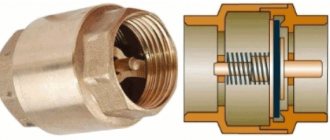
Gravity check valve for heating
It is also called a firecracker valve and is used only in gravity systems, usually installed at the inlet to the boiler. It consists of a metal “petal”, which is pressed tightly against the edge using a spring.
The spring in the gravity check valve is quite weak and does not interfere with the natural circulation of the coolant.
The spring in such a device is quite weak and does not interfere with the natural circulation of the coolant, like the next presented option.
Ball valve for heating
It is used less often, since there is a danger that the ball, which moves inside the mechanism, opening and closing the flow of water, may jam in one position and then the device will not perform its job properly.
This feature has led to the fact that today the ball check valve is practically not used in heating networks of private houses.
Disc-shaped
This product is used in networks that operate with a pump, as well as those with several active heating circuits. This is due to the fact that the spring located inside the device has greater rigidity, and therefore resistance.
Inside there is a metal or plastic disk (metal is always used for heating), combined with a sleeve on which a spring is attached. Thus, when the proper pressure occurs in the pipe, the plate rises and does not interfere with the flow of coolant. However, as soon as the pressure drops, the opening closes, preventing the outflow of water in the opposite direction.
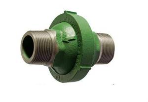
Coupled
All the products discussed above were completely autonomous and were not subject to external influences, working only in one direction. But in cases where it is necessary, for example, to drain coolant from pipes, a device is needed that makes it possible to open the coolant flow in the opposite direction - such a device is a coupling or valve valve.
When it is necessary to drain coolant from pipes, you need a device that makes it possible to open the coolant flow in the opposite direction; for this, a coupling or valve valve is used.
The choice between a coupling and a valve is most often determined by the internal operating pressure of the network; if it is high, a valve is used; if it is average, a coupling will suffice.
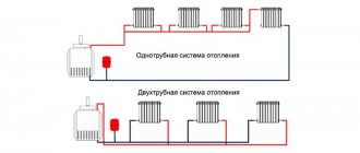
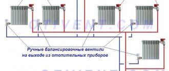
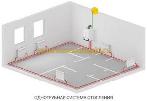
Types of wiring of a single-pipe system
In a one-pipe system there is no separation between forward and return pipes. The radiators are connected in series, and the coolant, passing through them, gradually cools down and returns to the boiler. This feature makes the system economical and simple, but requires adjusting the temperature regime and correctly calculating the power of the radiators.
A simplified version of the single-pipe system is only suitable for a small one-story house. In this case, the pipe passes through all radiators directly, without temperature-regulating valves. As a result, the first batteries along the coolant path turn out to be much hotter than the last ones.
For extended systems, such wiring is not suitable. After all, the cooling of the coolant will be significant. For them, they use a single-pipe “Leningradka” system, in which the common pipe has adjustable outlets for each radiator. As a result, the coolant in the main pipe is more evenly distributed throughout all rooms. The wiring of a single-pipe system in multi-story buildings is divided into horizontal and vertical.
Horizontal layout
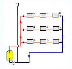
With horizontal wiring, a straight pipe rises to the top floor along the main riser.
A horizontal pipe departs from it on each floor, passing sequentially through all the batteries on a given floor. They are combined into a return riser and returned to the boiler or boiler. Taps for temperature control are located on each floor, and Mayevsky taps are on each radiator. Horizontal wiring can be done either through flow or using the Leningradka system.
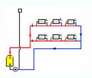
Vertical layout
With this type of wiring, the hot coolant rises to the topmost floor or attic, and from there it passes through vertical risers through all floors to the lowest.
There the risers are combined into a return line. A significant drawback of this system is uneven heating on different floors, which cannot be adjusted with a flow-through system. The choice of wiring system for a private house depends mainly on its layout. With a large area of each floor and a small number of floors in the house, it is better to choose vertical wiring, this way you can achieve a more even temperature in each room. If the area is small, it is better to choose horizontal wiring, as it is easier to regulate. In addition, with a horizontal type of wiring, you will not have to make extra holes in the ceilings.
Video: single-pipe heating system
The principle of operation of a natural circulation system
The heating scheme for a private house with natural circulation is popular due to the following advantages:
- Easy installation and maintenance.
- No need to install additional equipment.
- Energy independence – no additional energy costs are required during operation. When the power goes out, the heating system continues to operate.
The operating principle of water heating, using gravity circulation, is based on physical laws. When heated, the density and weight of the liquid decreases, and when the liquid medium cools, the parameters return to their original state.
At the same time, there is practically no pressure in the heating system. In thermotechnical formulas, the ratio of 1 atm is accepted. for every 10 m of water column pressure. Calculation of the heating system of a 2-story building will show that hydrostatic pressure does not exceed 1 atm. in one-story buildings 0.5-0.7 atm.
Since the liquid increases in volume when heated, an expansion tank is required for natural circulation. The water passing through the boiler water circuit heats up, which leads to an increase in volume. The expansion tank should be located on the coolant supply, at the very top of the heating system. The purpose of the buffer tank is to compensate for the increase in liquid volume.
A self-circulating heating system can be used in private homes, making the following connections possible:
- Connection to heated floors - requires installing a circulation pump, only on a water circuit laid in the floor. The rest of the system will continue to operate with natural circulation. After a power outage, the room will continue to be heated using the installed radiators.
- Working with an indirect water heating boiler - connection to a system with natural circulation is possible, without the need to connect pumping equipment. To do this, the boiler is installed at the top point of the system, just below the air expansion tank of a closed or open type. If this is not possible, then the pump is installed directly on the storage tank, additionally installing a check valve to avoid recirculation of the coolant.
In systems with gravitational circulation, the coolant moves by gravity. Thanks to natural expansion, the heated liquid rises up the accelerating section, and then “flows” down an incline through pipes connected to the radiators back to the boiler.
Making your own check valve for water
A homemade check valve for installation on a pipeline through which water is transported does not require expensive consumables and complex equipment in its manufacture, which makes it possible to save a lot of money. So, to make a check valve yourself, you need to prepare:
- a coupling with an external thread cut into its body;
- female tee;
- a spring, the diameter of which allows it to freely enter the tee;
- a steel ball, the diameter of which is slightly smaller than the cross-section of the internal cavity in the tee;
- screw plug;
- sealing tape FUM.
If you don’t find a spring with a suitable diameter, you can make it yourself, using a rod of the appropriate diameter and rigid steel wire. It is necessary to drill a hole in the rod on which the homemade spring will be wound; the end of the wire will be inserted into it. To make winding the spring more convenient, the rod can be clamped in a vice, and the wire winding itself can be done using pliers.
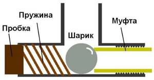
Diagram of a homemade check valve for water
After all the materials for making a homemade check valve have been prepared, you can begin assembly, which is performed in the following sequence.
- A coupling is screwed into the internal threaded hole of the tee. This is done in such a way that it overlaps the side hole by approximately 2 mm. It is necessary to fulfill this requirement when tightening the coupling so that the ball, which will be located in the inner part of the tee, does not jump out into its side hole.
- A ball is first inserted into the hole located on the opposite side of the tee, and then a spring.
- The hole in the tee into which the ball and spring were inserted is plugged with a screw plug, tightened using FUM tape.
A check valve made according to the proposed scheme will work as follows: the flow of water entering such a device from the coupling side will push away the ball, pressed by the spring, and exit through the perpendicularly located hole of the tee.
The most important thing when making a check valve of the proposed design with your own hands is to correctly adjust the spring so that it does not deviate at the moment when the water pressure in the pipeline decreases, and at the same time is not too tight so as not to impede the flow of water passing through the device. In addition, all threaded connections must be made very well to ensure absolute tightness of the check valve.
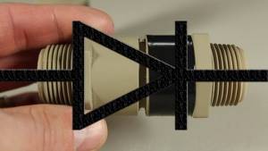
The check valve can also be made from a polypropylene tube and fitting. The manufacturing process is very simple and is shown in the photo below.
Increasing temperatures
Another factor is the difference between the density of cold and hot water. Let us note the following fact - heating with natural circulation is of a self-regulating type. Thus, if you increase the heating temperature of water, its flow rate changes and the circulation pressure becomes higher.
Strong heating of the liquid greatly contributes to faster circulation. But this only happens in a cold room: when the air temperature in them reaches a certain point, the batteries will cool much more slowly.
The density of both the water heated in the boiler and the water that has already entered the radiators will be almost equal. The pressure will decrease, the rapid circulation of water will be replaced by measured circulation within the system.
As soon as the temperature in the premises of a private house drops again to a certain level, this will serve as a signal to increase the pressure. The system will try to equalize temperature conditions. To do this, you will have to restart the rapid circulation process. This is where the ability to self-regulate comes from.
Briefly, the rule is as follows: a one-time change in the temperature and volume of water allows you to obtain the desired thermal output from the radiators for heating the premises.
As a result, comfortable temperature conditions are maintained.
Action diagram
The water heating system includes a boiler (water heater), return and supply pipelines, as well as heating equipment, an expansion tank and a safety valve. The liquid is heated to the required temperature in the boiler and rises into the supply pipeline and risers due to expansion.
From there it goes into heating equipment - batteries and radiators, to which it gives off some of the heat. The return pipeline then directs the water to the boiler, where it is again heated to the set temperature. The cycle repeats as long as the system is operational.
It is important to remember that horizontal pipes are installed with a slope relative to the movement of the working medium
Reed check valve
In most cases, they are used in boiler houses and large heating points with pipeline diameters of DN50 and above.
Leaf valve Ebro Armaturen (Germany) type DC, with sizes from DN 50 to DN 300.
The valve body is made of cast iron or stainless steel. The locking mechanism consists of two petals (flaps) attached to a rod located in the center of the structure. The petals are supported in the closed position by several torsion springs.
The disadvantages of the reed valve include “weak” hydraulics. This is due to the fact that the petals in the open position and the rod are in the center of the section, directly in the path of the coolant flow.
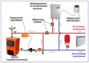
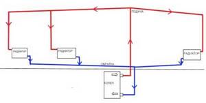
Design of heating with forced circulation
Detailed house heating diagram
The first priority when installing water heating with a circulation pump yourself is to draw up the correct diagram. To do this, you need a house plan, which shows the location of pipes, radiators, shut-off valves and safety groups.
System calculation
At the stage of drawing up diagrams, it is necessary to correctly calculate the parameters of the pump for the forced heating system of a private house. To do this, you can use special programs or do the calculations yourself. There are a number of simple formulas that will help you make the calculation:
Where Рн is the rated power of the pump, kW, р is the coolant density, for water this figure is 0.998 g/cm³, Q is the coolant flow rate, l, N is the required pressure, m.
Example of a heating calculation program
To calculate the pressure indicator in a forced heating system at home, you need to know the total resistance of the pipeline and heat supply as a whole. Alas, it is almost impossible to do this on your own. To do this, you should use special software systems.
By calculating the resistance of the pipeline in a water heating system with circulation, you can calculate the required pressure using the following formula:
Where N is the calculated pressure, m, R is the pipeline resistance, L is the length of the largest straight section of the pipeline, m, ZF is a coefficient, which is usually equal to 2.2.
Based on the results obtained, the optimal model of the circulation pump is selected.
If the estimated pump power of a self-installed forced circulation heating system is high, it is recommended to purchase paired models.
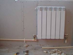
Installation of heating with circulation
An example of hidden installation of collector heating
Based on the calculated data, pipes of the required diameter are selected, and shut-off valves are selected for them. However, the diagram does not show how to install the main line. Pipelines can be installed in a hidden or open way. The first is recommended to be used only if you are fully confident in the reliability of the entire heating system of a private cottage with forced circulation.
It must be remembered that the quality of the system components will determine its performance and performance. This is especially true for the materials used to make pipes and valves. In addition, for a two-pipe forced circulation heating system, it is recommended to listen to the advice of professionals:
- Installation of an emergency power supply for the circulation pump in the event of a power outage;
- When using antifreeze as a coolant, you should check its compatibility with the materials used to make pipes, radiators and the boiler;
- According to a house heating scheme with forced circulation, the boiler should be located at the lowest point of the system;
- In addition to the pump power, it is necessary to calculate the expansion tank.
The technology for installing circulation-type heating is no different from the standard one.
It is important to take into account the features of a contoured house - the material of the walls, its heat losses. The latter directly affects the power of the entire system
Analysis of the parameters of forced circulation heating systems will help you form an objective opinion about it:
Types of locking elements
Any check valve (the outdated name is non-return) performs a simple task - it does not allow the coolant flow to change direction, passing liquid only in one direction. In water heating schemes, this function is not always needed and is implemented as needed.
The following types of check valves are used in heating systems of private houses and apartments:
- petal;
- disc-shaped;
- ball
For reference. In industrial production and the water supply sector, there are other types of products - double-leaf, lifting and disk, used as network elements on large pipelines. In private housing construction, such fittings are not used.
Let us analyze the device and operating principle of each type of valve separately. In the future, this will help you understand which product is best to select and install in a specific heating system.
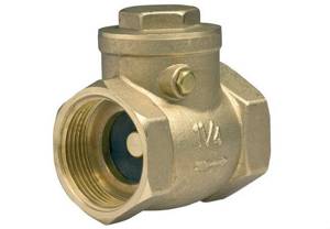
Reed valves
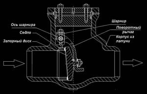
The element, made of brass or stainless steel, consists of the following parts:
- body in the form of a tee with a unscrewing top plug (for maintenance);
- a butterfly valve mounted on an axis by means of a rotary lever;
- a seat with a seal into which the disc fits when closed.
Note. There are 2 versions of the products - with a free or spring-loaded petal. In the second case, the sash is forced to close with a spring so that the lock operates in a vertical position.
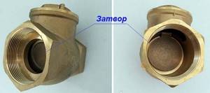
The general design of a reed check valve is shown in the detailed drawing. The principle of operation of the element is as follows: the coolant moving in the indicated direction deflects the locking disc and freely passes further along the pipe. When the direction of water flow is reversed, the valve, under the influence of gravity (or a spring), automatically slams shut and blocks the passage.
Typical gravity seal design
For reference. Due to the principle of operation, the products received several names - gravitational, rotary, “crackers”.
We list the important characteristics of petal check valves installed in heating systems of private houses:
- internal passage diameter – from 15 to 50 mm (½—2 inches);
- maximum working pressure – 16 Bar;
- low hydraulic resistance;
- There is a screw on the side of the body for disassembling and adjusting the shutter axis;
- The gravity version without spring can only work normally in a horizontal position.
The design and operating principle of the rotary valve is shown in detail in the video:
Poppet valves
The principle of operation of a poppet check valve is clear from its design, shown in the drawing:
- Inside the cylindrical brass body there is a platform with a round hole - a saddle.
- On the other side of the part there is a partition with a hole in the center.
- A rod with a disc-type valve at the end equipped with a seal is inserted into the hole in the partition.
- A spring is installed between the partition and the “plate”, pressing the disk to the seat.
Water flowing in the right direction overcomes the elastic force of the spring, opens the valve and moves on. Flow in the opposite direction is impossible - the duct instantly closes. What properties of a check valve are important for heating systems:
- ability to function in any orientation of the body in space;
- working pressure – not less than 10 Bar, diameters DN15 – DN100 (internal);
- type of connection – coupling (internal pipe thread);
- spring lock creates increased hydraulic resistance to fluid flow;
- The seal loses its tightness if solid particles, such as sand, enter.
In the utility networks of private houses and apartments, valves with coupling connections are used
Reference. There are more compact versions of spring check valves that are installed between flanges. Reducing the dimensions can be useful when installing boiler piping in conditions of limited combustion space.
Disc locks are also used in water supply networks, for example, in conjunction with submersible pumps. The valve prevents water from the pipelines from flowing back into the well or borehole.
Ball valves
This is a check valve of the simplest design, operating on the following principle:
- Inside the cylindrical brass body there is a ball made of rubber, less often aluminum.
- The ball is prevented from jumping out by 2 partitions with holes made along the edges.
- The coolant flow presses the rubber ball against the partition with ribs. These protrusions form a gap where water flows freely.
- If the coolant moves in the opposite direction, the ball will press against the second jumper - the seat. Since there are no ribs, the body of the ball will completely cover the passage hole.
What it is
If a system with forced circulation requires a pressure difference created by a circulation pump or provided by a connection to the heating main, then the picture is different. Natural circulation heating uses a simple physical effect - the expansion of a liquid when heated.
If we ignore the technical details, the principle of operation is as follows:
- The boiler heats a certain volume of water. So, of course, it expands and, due to its lower density, is forced upward by a colder mass of coolant.
- Having risen to the top point of the heating system, the water, gradually cooling, describes a circle by gravity through the heating system and returns to the boiler. At the same time, it gives off heat to the heating devices and by the time it reaches the heat exchanger again, it has a higher density than at the beginning. Then the cycle repeats.
Useful: of course, nothing prevents you from including a circulation pump in the circuit. In normal mode, it will provide faster circulation of water and uniform heating, and in the absence of electricity, the heating system will operate with natural circulation.
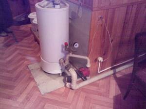
Pump operation in a natural circulation system.
The photo shows how the problem of interaction between the pump and the natural circulation system was solved. When the pump is running, the check valve is activated, and all the water flows through the pump. Once you turn it off, the valve opens and water circulates through the thicker pipe due to thermal expansion.
Advantages and disadvantages
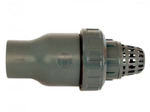
A check valve with a filter helps prevent the plate from jamming in any position.
The check valve has advantages and disadvantages that are common to all types of devices. There will be no hot flow into the riser if cold liquid flows there. This extends the performance of system elements that are designed for a certain temperature. The devices are easy to install and do not create noise during the passage of liquid. Check valves solve the problem only in a specific area; additional control devices are installed for other circuits.
Some mechanisms allow the occurrence of water hammer when the flow passes through the working unit, but this feature of the valve only harms a system with a large diameter. The valves become dirty from the water flow if the system operates with an energy carrier without propylene glycol or other additives. In this case, the disc or plate may become stuck in the open or closed position.
Boiler for gravity systems
Since such circuits are mainly needed for heating independent of electricity, the boilers must operate without the use of electricity. These can be any non-automated units, except pellet and electric ones.
Most often, solid fuel boilers operate in natural circulation systems. They are all good, but in many models the fuel burns out quickly. And if there is severe frost outside, and the house is not sufficiently insulated, then in order to maintain an acceptable temperature at night you have to get up and add fuel. This situation is especially common where people heat with wood. The solution is to buy a long-burning boiler (non-volatile, of course). For example, in Lithuanian solid fuel boilers Stropuva, under certain conditions, wood burns for up to 30 hours, and coal (anthracite) for up to several days. Candle boilers have slightly worse characteristics: the minimum burning time for wood is 7 hours, for coal - 34 hours. There are boilers without automation and pumps from the German company Buderus, the Czech Viadrus and the Polish-Ukrainian Wikchlach, as well as the Russian company Ogonyok.
Non-volatile long-burning boiler Stropuva
There are gas-independent boilers made in Russia, for example Conord. which are produced in Rostov-on-Don. They can be used in systems with natural circulation. The same plant produces energy-independent universal boilers “Don”, which are also suitable for operation without electricity. Floor-standing gas boilers from the Italian company Bertta, the Novella Autonom model, and some other units from European and Asian manufacturers operate in systems with natural circulation.
The second way to increase the time between fires is to increase the inertia of the system. For this purpose, heat accumulators (TA) are installed. They work well with solid fuel boilers, which do not have the ability to regulate the combustion intensity: excess heat is transferred to a heat accumulator, in which energy is accumulated and consumed as the coolant in the main system cools. Connecting such a device has its own characteristics: it must be located on the supply pipeline below. Moreover, for efficient heat extraction and normal operation - as close as possible to the boiler. However, for gravitational systems this solution is far from the best. They return to normal circulation quite slowly, but are self-regulating: the colder the room, the more the coolant cools as it passes through the radiators. The greater the temperature difference, the greater the density difference and the faster the coolant moves. And the installed TA makes the heating more inertial, and it takes much more time and fuel to accelerate. True, the heat is released longer. In general, it's up to you.
To stabilize the temperature, a heat accumulator is installed in the system
Stove heating with natural circulation has approximately the same problems. Here the role of a heat accumulator is played by the furnace array itself and a lot of energy (fuel) is also required to accelerate the system. But in the case of using TA, it is usually possible to exclude it, but in the case of a stove this is unrealistic.
From the laws of physics
Suppose that in radiators and a boiler the temperature of the liquid changes abruptly along the central axes: the upper parts contain hot liquid, and the lower parts contain cold liquid.
Hot water is less dense, which reduces its weight compared to cold water. As a result, the heating system consists of two communicating vessels, closed to each other, in which liquid moves from top to bottom.
The high column, formed by cooled water with a large weight, pushes out the low column upon reaching the radiators. As a result, the hot liquid is pushed and circulation occurs.
Types of heating systems with gravity circulation
Despite the simple design of a water heating system with self-circulation of coolant, there are at least four popular installation schemes. The choice of wiring type depends on the characteristics of the building itself and the expected performance.
To determine which scheme will work, in each individual case it is necessary to perform a hydraulic calculation of the system, take into account the characteristics of the heating unit, calculate the diameter of the pipe, etc. You may need professional help when performing the calculations.
Closed system with gravity circulation
In EU countries, closed systems are the most popular among other solutions. In the Russian Federation, the scheme has not yet received widespread use. The operating principles of a closed-type water heating system with pumpless circulation are as follows:
- When heated, the coolant expands and water is displaced from the heating circuit.
- Under pressure, the liquid enters a closed membrane expansion tank. The design of the container consists of a cavity divided by a membrane into two parts. One half of the tank is filled with gas (most models use nitrogen). The second part remains empty for filling with coolant.
- When the liquid is heated, pressure is created sufficient to push through the membrane and compress the nitrogen. After cooling, the reverse process occurs and the gas squeezes water out of the tank.
Otherwise, closed-type systems work like other heating schemes with natural circulation. The disadvantages include the dependence on the volume of the expansion tank. For rooms with a large heated area, you will need to install a spacious container, which is not always advisable.
Open system with gravity circulation
The open type heating system differs from the previous type only in the design of the expansion tank. This scheme was most often used in old buildings. The advantage of an open system is the ability to independently manufacture a container from scrap materials. The tank usually has modest dimensions and is installed on the roof or under the ceiling of the living room.
The main disadvantage of open structures is the entry of air into pipes and heating radiators, which leads to increased corrosion and rapid failure of heating elements. Airing of the system is also a frequent “guest” in open-type circuits. Therefore, radiators are installed at an angle; Mayevsky valves must be provided to bleed air.
Single-pipe self-circulating system
This solution has several advantages:
- There is no pair pipeline under the ceiling and above the floor level.
- Saves money on system installation.
The disadvantages of this solution are obvious. The heat transfer of heating radiators and the intensity of their heating decreases with distance from the boiler. As practice shows, a single-pipe heating system for a two-story house with natural circulation, even if all slopes are observed and the correct pipe diameter is selected, is often redone (by installing pumping equipment).
Two-pipe self-circulating system
A two-pipe heating system in a private house with natural circulation has the following design features:
- Supply and return flow through different pipes.
- The supply pipeline is connected to each radiator through an inlet branch.
- The second line connects the battery to the return line.
As a result, a two-pipe radiator-type system provides the following advantages:
- Even heat distribution.
- No need to add radiator sections for better heating.
- Easier to adjust the system.
- The diameter of the water circuit is at least one size smaller than in single-pipe circuits.
- Lack of strict rules for installing a two-pipe system. Small deviations regarding slopes are allowed.
The main advantage of a two-pipe heating system with bottom and top wiring is the simplicity and at the same time efficiency of the design, which allows you to eliminate errors made in calculations or during installation work.
Power calculation
The effective thermal output of the boiler is calculated using the same methods as in all other cases.
By area
The simplest method is the calculation based on the area of the room recommended by SNiP. 1 kW of thermal power should be per 10 m2 of room area. For the southern regions, a coefficient of 0.7 - 0.9 is taken, for the central zone of the country - 1.2 - 1.3, for the Far North - 1.5-2.0.
Like any rough calculation, this method neglects many factors:
- Ceiling height. It is not always the standard 2.5 meters.
- Heat leaks through openings.
- The location of the room is inside the house or near external walls.

All calculation methods give large errors, so thermal power is usually included in the project with some margin.
By volume, taking into account additional factors
Another method of calculation will give a more accurate picture.
- The basis is a thermal power of 40 watts per cubic meter of air volume in the room.
- Regional coefficients apply in this case as well.
- Each standard size window adds 100 watts to our calculations. Each door is 200.
- The location of the room near the external wall will give, depending on its thickness and material, a coefficient of 1.1 - 1.3.
- A private house, which has not warm neighboring apartments below and above, but a street, is calculated with a coefficient of 1.5.
However: this calculation will also be VERY approximate. Suffice it to say that in private houses built using energy-saving technologies, the design includes a heating power of 50-60 watts per SQUARE meter. Too much is determined by heat leakage through walls and ceilings.
Advantages of installing a two-pipe system
When designing water heating with forced circulation for a private house, they choose, based on the financial capabilities of the owner, a one-pipe or two-pipe scheme. A one-pipe system is cheaper and easier to install, while a two-pipe system is more efficient in operation. When installing a horizontal two-pipe heating system, three pipeline layouts are possible: dead-end, associated and collector.
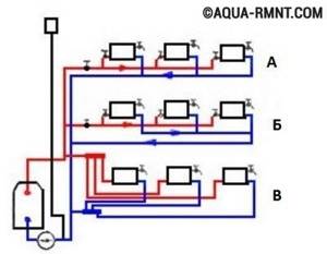
Three schemes for installing a horizontal two-pipe heating system in a private house: A) dead-end; B) passing; B) collector (radial)
Let us immediately note that the latter, namely collector pipe routing, has the greatest efficiency. However, its implementation increases the consumption of materials, as well as the complexity of installation work.
Installation and configuration rules
The valve must be installed in the direction of the main current; for this there is an arrow on the body. The joints are sealed using paronite, but the gasket is placed so that the internal diameter of the passage device does not decrease. The condition is important to prevent water hammer in the pipeline network.
The device is installed so that other elements of the highway do not affect its operation. The section of pipe containing the valve may be supported by a metal frame to prevent vibration or other disturbances. A mesh is placed in front of the passage mechanism for rough cleaning of solid impurities.