Selecting a heating element
When choosing a heating element, you need to pay attention to some details. Only in this case can you count on a successful purchase, high-quality heating, long service life and compatibility of the selected model with a water heating tank, boiler or radiator
Shape and size
There are dozens of heating element models available for buyers to choose from. They have different shapes - straight, round, figure-eight or ear-shaped, double, triple and many others. When purchasing, you should focus on the use of the heater. For installation in sections of heating radiators, narrow and straight models are used, since there is quite little space inside
When assembling a storage water heater, you should pay attention to the volume and shape of the tank, and based on this, choose a suitable heating element. In principle, almost any model will fit here
If you need to replace a heating element in an existing water heater, you need to purchase an identical model - only in this case can you count on the fact that it will fit into the tank itself.
Power
If not everything, then a lot depends on power. For example, this could be the heating rate. If you are assembling a small-volume water heater, the recommended power will be 1.5 kW. The same heating element will be able to heat disproportionately large volumes, but it will do this for a very long time - with a power of 2 kW, heating 100-150 liters of water can take 3.5 - 4 hours (not to a boil, but on average by 40 degrees).
If you equip a water heater or water tank with a powerful 5-7 kW heating element, the water will heat up very quickly. But another problem will arise - the house electrical network will not withstand it. When the power of the connected equipment is above 2 kW, it is necessary to lay a separate line from the electrical panel.
Protection against corrosion and scale
When choosing heating elements for heating water with a thermostat, we recommend paying attention to modern models equipped with scale protection. Recently, models with enamel coating have begun to appear on the market.
It is this that protects the heaters from salt deposits. The warranty on such heating elements is 15 years. If you don’t find similar models in the store, then we recommend purchasing stainless steel electric heaters - they are more durable and reliable.
The presence of a thermostat
If you are assembling or repairing a boiler or want to equip a heating element with a heating element, choose a model with a built-in thermostat. It will save on electricity by turning on only when the water temperature drops below a set point. If there is no regulator, you will have to monitor the temperature yourself by turning the heating on or off - this is inconvenient, uneconomical and unsafe.
How to connect a boiler, diagram of connecting a boiler through an electrical outlet
Industrial models of small power up to 1.5 ÷ 2 kilowatts are created, as a rule, for such a connection. With this method, long-term safe operation is ensured by:
- the technical condition of the boiler, which changes during long-term operation
- correct choice of socket design for load power
- accounting of the state of electrical circuits through which voltage is supplied from the apartment panel
- the use of protective devices that prevent the consequences of accidental accidents in the circuit
Features of connecting the boiler to the electrical network via an outlet
The power contacts of a detachable switching device are designed for a specific type of load, for example, 6, 10 or 16 amperes. Its size is indicated on the body. If the socket is of less power, overheating and destruction of contacts occurs. For this reason, you cannot connect the boiler to a random outlet that does not correspond to its load.
Another requirement for the safe operation of such a circuit is the need to have an automatic switch in it, through which you can break the power supply circuit of the heating element under load. The socket and plug contacts are not designed to extinguish the electric arc that occurs in this case.
Wiring condition
The household network wires connecting the socket for the boiler to the apartment panel will fully carry the load of the heating element. They should not overheat. Their material and thickness must be taken into account correctly, otherwise a fire may occur.
A heating element cannot be connected to a socket with aluminum wiring, as well as to a copper one thinner than 2.5 mm2. It is better to use a 4 or 6 square section. It must first be calculated based on heat release and analyzed based on installation methods.
Protective devices
The boiler is designed to operate at the nominal characteristics of the electrical network, taking into account the occurrence of random faults in it. To prevent accidents, protection from:
- increasing pressure in the tank
- breakdown of electrical insulation
If the equipment manufacturer has not provided such protections in the internal design, then they should be mounted in the housing panel.
Emergency mode with excess pressure inside the boiler
A mandatory safety condition is the presence of a device that prevents the boiling of water and the release of dissolved gases from it, because this process creates increased pressure that can rupture the housing.
A similar situation may arise:
- when power contacts stick, when they receive a command from a temperature sensor through the control unit and are not able to break the electric current through the heating element
- malfunction of the temperature sensor, logic unit or connecting control circuits
To prevent such an accident, use a second stage of protection, set to a higher temperature setpoint than for the operating mode. Its value is selected close to the boiling point, and shutdown is carried out by another, backup contact.
Such an open circuit is called a thermal fuse. The use of a separate temperature sensor for it or the use of an autonomous mechanical design operating on the principles of bimetallic releases increases the overall reliability of the system.
Emergency mode with leakage currents
The metal casing of the boiler may be at phase potential if the insulation of the heating element or connecting wires to the casing breaks down. This situation is a direct prerequisite for a person to receive an electrical injury. It can be corrected by an RCD built into the electrical circuit. Industrial samples of boilers may be produced with a built-in protective shutdown device or not have it.
For proper operation of the RCD, it is necessary to ensure a reliable connection of the boiler body with the main grounding bus through a protective PE conductor.
Short circuit of internal circuits
A circuit breaker is designed to disconnect the electrical circuit from a short circuit.
Purpose of heating elements
Why do we need heating elements with thermostats? Based on them, autonomous heating systems are designed, boilers and instantaneous water heaters are created.
For example, heating elements are mounted directly into batteries, resulting in sections that can operate independently, without a heating boiler. Some models are focused on creating anti-freeze systems - they maintain a low positive temperature, preventing freezing and subsequent rupture of pipes and batteries.
This battery has a built-in heating element with a thermostat, with its help the house is heated.
Storage and instantaneous water heaters are created on the basis of heating elements. Purchasing a boiler is not affordable for every person, so many assemble them themselves using separate components. By installing a heating element with a thermostat into a suitable container, we will get an excellent storage-type water heater - the consumer will only have to equip it with good thermal insulation and connect it to the water supply.
Bulk-type storage water heaters are also being created on the basis of heating elements. In fact, it is a container of water that is filled manually. Heating elements are also built into summer shower tanks, ensuring water heating to a given temperature in bad weather.
Heating elements for heating water with a thermostat are necessary not only for creating water heating equipment, but also for repairing it - if the heater fails, we buy a new one and replace it. But before that, you need to understand the issues of choice.
Power measurement. Power measurement in direct and single-phase current circuits
The power in DC circuits consumed by this section of the electrical circuit is equal to:
and can be measured with an ammeter and voltmeter.
In addition to the inconvenience of simultaneous reading of two instruments, power measurement by this method is carried out with inevitable error. It is more convenient to measure power in DC circuits with a wattmeter.
It is impossible to measure active power in an alternating current circuit with an ammeter and voltmeter, because the power of such a circuit also depends on cosφ:
Therefore, in AC circuits, active power is measured only with a wattmeter.
Figure 8
Fixed winding 1-1 (current) is connected in series, and movable winding 2-2 (voltage winding) is connected in parallel with the load.
To correctly turn on the wattmeter, one of the current winding terminals and one of the voltage winding terminals are marked with an asterisk (*). These terminals, called generator terminals, must be turned on from the power supply side by combining them together. In this case, the wattmeter will show the power coming from the network (generator) to the electrical energy receiver.
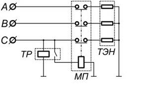
Let's consider connecting a three-phase heating element through a magnetic starter and a thermal relay.

Rice.
1 The heating element is connected through one three-phase MP with normally closed contacts (Fig. 1). The starter is controlled by a thermal relay TP, the control contacts of which are open when the temperature at the sensor is below the set one. When three-phase voltage is supplied, the contacts of the starters are closed and the heating element is heated, the heaters of which are switched on in a “star” configuration. Rice. 2 When the set temperature is reached, the thermal relay turns off the power to the heaters. Thus, a simple temperature controller is implemented. For such a regulator, you can use a RT2K thermal relay (Fig. 2), and for a starter, a third-value contactor with three opening groups.
RT2K is a two-position (on/off) thermal relay with a copper wire sensor with a temperature setting range from -40 to +50°C. Of course, using one thermal relay does not allow you to accurately maintain the required temperature. Turning on all three sections of the heating element each time leads to unnecessary energy losses.
Rice. 3 If you control each section of the heater through a separate starter connected to its own thermal relay (Fig. 3), then more accurate temperature maintenance can be achieved. So, we have three starters, which are controlled by three thermal relays TP1, TP2, TP3. The response temperatures are selected, let's say t1
Rice. 4 Relay-temperature sensors provide switching of the executive circuit up to 6A, at a voltage of 250V. To control a magnetic starter, such values are more than enough (For example, the operating current of PME contactors is from 0.1 to 0.9 A at a voltage of 127 V). When alternating current passes through the armature coil, a low hum of industrial frequency 50 Hz is possible. There are thermal relays that control the current output with a current value from 0 to 20 mA. Thermal relays are also often powered by low voltage DC (24 V). To match such an output current with low-voltage (24 to 36 V) starter armature coils, a level-matching circuit on a transistor can be used (Fig. 5)
Rice. 5 This circuit operates in key mode. When current is supplied through the contacts of the thermal relay TP through resistor R1, to the base VT1 the current is amplified and the MP starter is turned on. Resistor R1 limits the current output of the thermal relay to prevent overload. Transistor VT1 is selected based on the maximum collector current, which exceeds the contactor operating current and the voltage on the collector.
Let's calculate resistor R1 using an example.
Let’s assume that a direct current of 200 mA is sufficient to control the starter’s armature. The current gain of the transistor is 20, which means that the control current of the base IB must be maintained within the range of up to 200/20 = 10 mA. The thermal relay produces a maximum of 24V at a current of 20mA, which is quite enough for the armature coil. To open the transistor in the switching mode relative to the emitter, the base voltage must be maintained at 0.6 V. Let us assume that the resistance of the emitter-base transition of an open transistor is negligible.
This means that the voltage on R1 will be 24 - 0.6V = 23.4 V. Based on the base current obtained earlier, we obtain the resistance: R1 = UR1/IB=23.4/0.01 =2.340 Kom. The role of resistor R2 is to prevent the transistor from turning on due to interference in the absence of control current. Usually it is chosen 5-10 times more than R1, i.e. for our example it will be approximately 24 kOhm. For industrial use, relay regulators are produced that realize the temperature of the object.
Write comments or additions to the article, maybe I missed something. Take a look at, I will be glad if you find something else useful on mine.
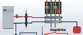
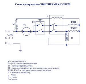
Design features of an electric boiler
Inside a hermetically sealed boiler with coolant - water circulating through hydraulic lines from pipelines and radiators located indoors, an electrical circuit is mounted, including:
- water heater, which is most often served by an ordinary resistive heating element
- coolant temperature meter - a sensor of a special design, the readings of which are processed by a logic circuit to supply voltage to the heating element or turn off its power
- switching device in double-pole or single-pole design - thermal switch
- protective thermal fuse
- heating indication circuit, which can be an ordinary incandescent light bulb or an LED with a current-limiting resistor connected in parallel to the contacts of the heating element
Manufacturers of electrical measuring and switching equipment produce ready-made kits that include temperature measurement sensors, switching devices and a logic unit that ensures their mutual connection to regulate the temperature of the coolant.
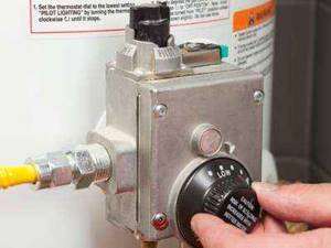
How to connect a boiler, mechanical thermostat
They are usually called thermostats or thermostats. The temperature sensor is mounted inside the boiler body, and the control unit and current switching contacts are located on the outside.
Thermostats can be made on an analog basis or use microprocessor technology. The designs of the latter have:
- greater adjustment possibilities
- easy-to-use setpoint settings
- user-friendly interface
- information board
- additional operational functions
An example is the model of an electronic thermostat TK-5 with a microcontroller, a display, and two temperature sensors mounted at the inlet and outlet of the coolant into the boiler. It allows you to take into account temperature changes within 0÷120 degrees with an error of 0.5 O C, which is more than enough for domestic purposes.
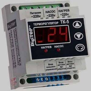
How to connect a boiler, electronic thermostat
The power contacts of the TK-5 thermostat are capable of switching rated currents of 6 amperes. When the heating element creates a larger load, the connection circuit of the boiler to the electrical network requires modernization - the inclusion of an additional magnetic starter that repeats the operation of the output circuits of the thermostat with high-power contacts.
Connecting a heating element with a thermostat
Let's consider the principle of operation and the connection diagram.
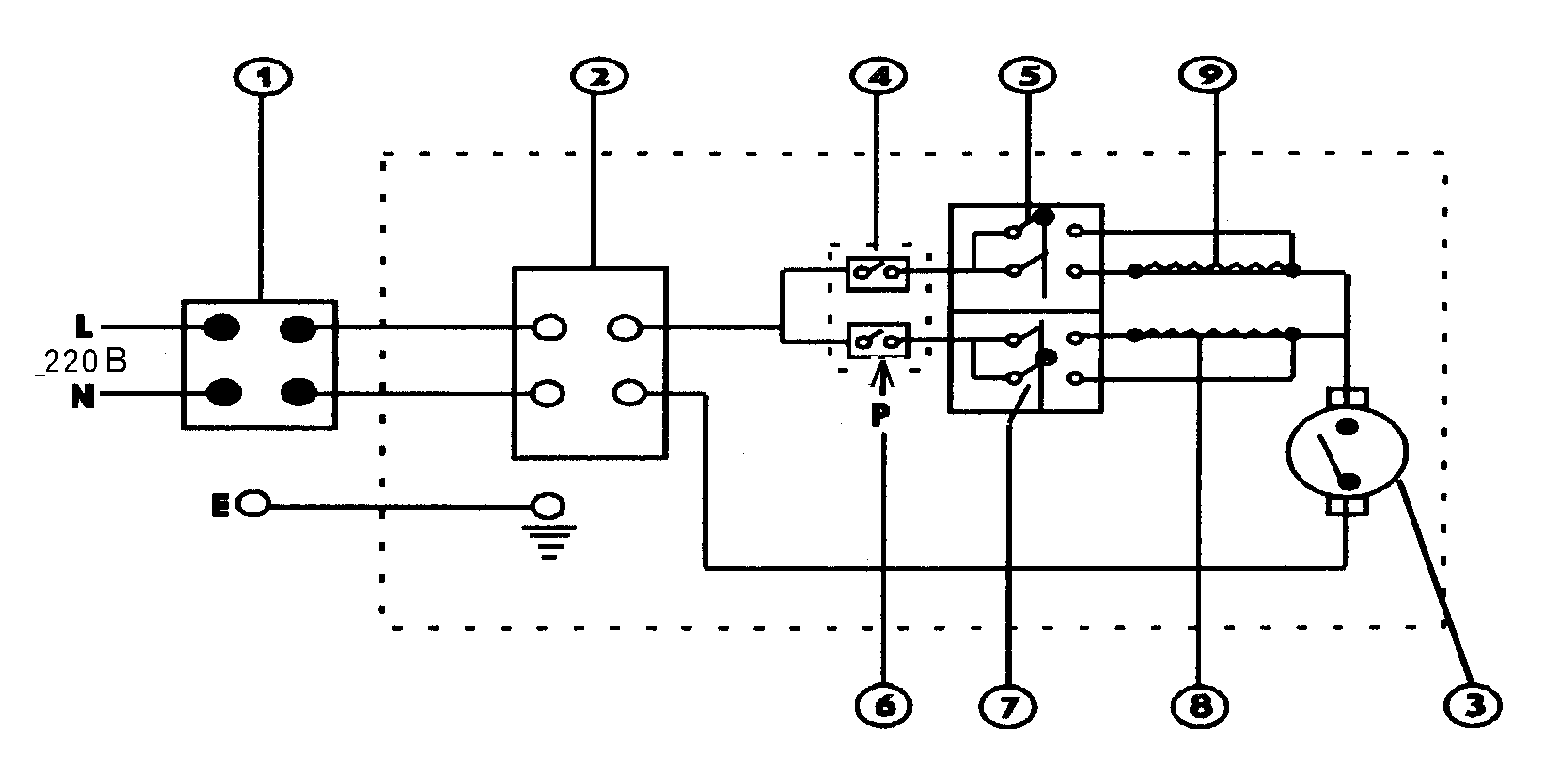
They are used for boilers and heating boilers. We take a universal one for 220V and 2-4.5 kW, a regular one, with a sensitive element in the form of a tube, it is placed inside the heating element, in which there is a special hole.
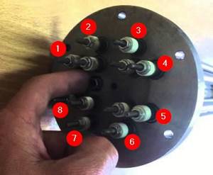
Here we see 3 pairs of heating elements, six in total, you need to connect as follows: set zero to three and phase to the other 3. We insert our device into the open circuit. It has three contacts, in the photo below you can see one in the center at the top and two at the bottom. The upper one is used to switch to zero, and which of the lower ones to phase should be checked with a tester.
Therefore, the power of the 1st heating element may not correspond to the parameters for heating the vessel and may be more or less. In such cases, to obtain the required heating power, you can use several heating elements connected in series or series-parallel. By switching various combinations of connecting heating elements, a switch from a household electric. plates, you can get different power. For example, having eight embedded heating elements, 1.25 kW each, depending on the switching combination, you can get the following power.
- 625 W
- 933 W
- 1.25 kW
- 1.6 kW
- 1.8 kW
- 2.5 kW
This range is quite enough to adjust and maintain the desired temperature. But you can get other power by adding the number of switching modes and using different switching combinations.
A series connection of 2 heating elements of 1.25 kW each and connecting them to a 220V network gives a total of 625 W. A parallel connection gives a total of 2.5 kW.
We know the current voltage in the network, it is 220V. Next, we also know the power of the heating element, knocked out on its surface, let’s say it’s 1.25 kW, which means we need to know the current flowing in this circuit. Knowing the voltage and power, we find out the current strength from the following formula.
Current = power divided by line voltage.
It is written like this: I = P / U.
Where I is the current strength in amperes.
P is power in watts.
U is voltage in volts.
When calculating, you need to convert the power indicated on the heating element body in kW into watts.
1.25 kW = 1250W. We substitute the known values into this formula and get the current strength.
I = 1250W / 220 = 5.681 A
R = U / I, where
R - resistance in Ohms
U - voltage in volts
I - current in amperes
We substitute the known values into the formula and find out the resistance of 1 heating element.
R = 220 / 5.681 = 38.725 Ohms.
Rtotal = R1+ R2 + R3, etc.
Thus, two series-connected heating elements have a resistance of 77.45 Ohms. Now it is easy to calculate the power released by these two heating elements.
P = U2 / R where,
P - power in watts
R is the total resistance of all lines. conn. heating elements
P = 624.919 W, rounded to 625 W.
Table 1.1 shows the values for series connection of heating elements.
Table 1.1
| Number of heating elements | Power, W) | Resistance (Ohm) | Voltage (V) | Current (A) |
| Serial connection | ||||
| 2 heating elements = 77.45 | ||||
| 3 heating element =1 16.175 | ||||
| 5 heating element = 193.625 | ||||
| 7 heating element=271.075 |
Table 1.2 shows the values for parallel connection of heating elements.
Table 1.2
| Number of heating elements | Power, W) | Resistance (Ohm) | Voltage (V) | Current (A) |
| Parallel connection | ||||
| 2 heating element = 19.3625 | ||||
| 3 heating element = 12.9083 | ||||
| 4 heating element=9.68125 | ||||
| 6 heating element = 6.45415 |
From the point of view of electrical engineering, this is an active resistance that generates heat when an electric current passes through it.
In appearance, a single heating element looks like a bent or curled tube. Spirals can be of very different shapes, but the connection principle is the same; a single heating element has two contacts for connection.
When connecting a single heating element to the supply voltage, we simply need to connect its terminals to the power supply. If the heating element is designed for 220 Volts, then we connect it to the phase and working zero. If the heating element is 380 Volt, then connect the heating element to two phases.
But this is a single heating element, which we can see in an electric kettle, but not in an electric boiler. The heating element of a heating boiler is three single heating elements mounted on a single platform (flange) with contacts located on it.
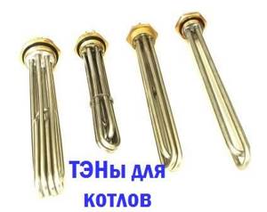
The most common boiler heating element consists of three single heating elements mounted on a common flange. On the flange there are 6 (six) contacts of the electric heating element of the boiler for connection. There are boilers with a large number of single heating elements, for example, like this:
Electric water heater device
Plumbing Electrical circuit of a water heater Hot water supply provides comfortable living conditions for a modern person. Installation of water heaters must be carried out in accordance with the markings indicated on the body of the water heater: Marking.
Here the difference is noticeable; for flow-through ones the price is rubles. Economical: in addition to heating the water itself, electricity is spent to compensate for heat loss through the insulation layer of the tank.
Familiarize yourself with the existing nuances to get the job done as efficiently as possible. The connection is made from the thermostat output terminals. This is done due to the small diameter of the fitting, to which only a rubber hose with a small cross-section can be attached.
At this moment, the transistor VT1 opens and the control electrode of the power thyristor VS1 is shunted to the minus of the circuit, from which it was previously separated by a voltage drop across the resistance of resistor R4.
This chain is configured so that with a current through the primary winding of 30A, a voltage of 45 volts is generated on the capacitor. The RCD and the automatic circuit breaker perform protective functions: the RCD eliminates the possibility of electric shock in the event of a leak, when the insulation is damaged or a breakdown occurs in the housing; Using a circuit breaker, the network is protected from overloads and short circuits.
The PE neutral protective conductor is connected to the tank body using a special screw. 21 Hot water recirculation scheme
We recommend: Energy efficiency analysis of buildings
Measurement of active power in three-phase current circuits
When measuring the power of three-phase current, various circuits for connecting wattmeters are used depending on:
wiring systems (three- or four-wire);
load (uniform or uneven);
load connection diagrams (star or delta).
a) power measurement under symmetrical load; three- or four-wire wiring system:
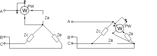
Figure 9 Figure 10
In this case, the power of the entire circuit can be measured with one wattmeter (Figures 9,10), which will show the power of one phase P=3P f =3U f I f cosφ
b) with an asymmetric load, the power of a three-phase consumer can be measured with three wattmeters:
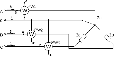
Figure 11
The total power of the consumer is equal to:
c) power measurement using the two-wattmeter method:
Figure 12
It is used in 3-wire three-phase current systems with symmetrical and asymmetrical loads and any method of connecting consumers. In this case, the current windings of the wattmeters are connected to phases A and B (for example), and the parallel windings to linear voltages U AC and U BC (or A and C U AB and U CA), (Fig. 12).
Total power P=P 1 +P 2.
Electric water heating and heating equipment has received great demand among consumers. It allows you to quickly organize heating and hot water supply with minimal initial costs. Some people even create such equipment on their own, with their own hands. And the heart of any homemade device becomes a heating element with a thermostat.
How to choose the right heating element and what to focus on when choosing it? There are quite a lot of parameters:
- Power consumption;
- Sizes and shape;
- Availability of built-in thermostat;
- Availability of corrosion protection.
After reading this review, you will learn how to independently understand heating elements with thermostats and be able to connect them.
Let's consider connecting a three-phase heating element through a magnetic starter and a thermal relay.
Rice.
1 The heating element is connected through one three-phase MP with normally closed contacts (Fig. 1). The starter is controlled by a thermal relay TP, the control contacts of which are open when the temperature at the sensor is below the set one. When three-phase voltage is supplied, the contacts of the starters are closed and the heating element is heated, the heaters of which are switched on in a “star” configuration. Rice. 2 When the set temperature is reached, the thermal relay turns off the power to the heaters. Thus, a simple temperature controller is implemented. For such a regulator, you can use a RT2K thermal relay (Fig. 2), and for a starter, a third-value contactor with three opening groups.
RT2K is a two-position (on/off) thermal relay with a copper wire sensor with a temperature setting range from -40 to +50°C. Of course, using one thermal relay does not allow you to accurately maintain the required temperature. Turning on all three sections of the heating element each time leads to unnecessary energy losses.
Rice. 3 If you control each section of the heater through a separate starter connected to its own thermal relay (Fig. 3), then more accurate temperature maintenance can be achieved. So, we have three starters, which are controlled by three thermal relays TP1, TP2, TP3. The response temperatures are selected, let's say t1
Rice. 4 Relay-temperature sensors provide switching of the executive circuit up to 6A, at a voltage of 250V. To control a magnetic starter, such values are more than enough (For example, the operating current of PME contactors is from 0.1 to 0.9 A at a voltage of 127 V). When alternating current passes through the armature coil, a low hum of industrial frequency 50 Hz is possible. There are thermal relays that control the current output with a current value from 0 to 20 mA. Thermal relays are also often powered by low voltage DC (24 V). To match such an output current with low-voltage (24 to 36 V) starter armature coils, a level-matching circuit on a transistor can be used (Fig. 5)
Rice. 5 This circuit operates in key mode. When current is supplied through the contacts of the thermal relay TP through resistor R1, to the base VT1 the current is amplified and the MP starter is turned on. Resistor R1 limits the current output of the thermal relay to prevent overload. Transistor VT1 is selected based on the maximum collector current, which exceeds the contactor operating current and the voltage on the collector.
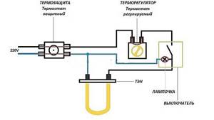
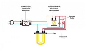
How does the heating element control unit circuit work?
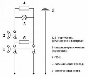
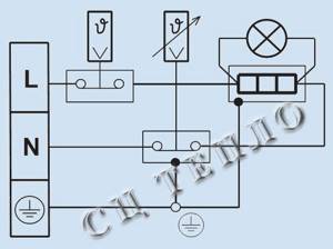
Modern electric boilers and other heating devices use thermostats and other devices to control the rise and fall of the temperature level. The relay ensures that the heater is turned on and off in a timely manner to maintain the set water temperature level. This diagram of the heating element control unit looks like this:
- The 220 V voltage is sent to the input of the two-pole switch. From the output of the machine it is sent to the power terminals of the thermal relay. Zero is connected to the thermal relay terminal A2 and the left terminal of the heating element.
- The phase is connected to the thermal relay terminal, with the help of a jumper it is directed to the left terminal of the contact, and the right terminal is connected to the left output of the heating element. A temperature sensor is also connected to the terminals.
This diagram looks like this:
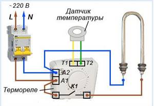
As long as the water temperature in the heater is above the set value, the relay opens the contact and the heater stops working. As soon as the temperature begins to drop and crosses the set point, this will be detected by the sensor, resulting in a signal being sent to the relay. The contact closes, the phase begins to flow to the right output of the heating element, as a result, the process of its operation resumes.
Likewise, as soon as the temperature exceeds the set threshold, the sensor will react to its increase and send a signal to the relay. As a result, the contact will open and the heater will temporarily stop working. Such a system will allow you to maintain the desired temperature level automatically without the constant presence and control of a person.