Home → Traffic safety → Operation of passenger cars and locomotives
In accordance with the technical conditions for the design and construction of passenger cars, the temperature inside them should be 20 ± 20 C. And in the toilets - not lower than 160 C with an outside air temperature of up to - 400 C and a speed of 160 km/h. In summer, the air temperature in the carriage should be from 22 to 260 C.
Content
- 1 General information
- 2 Classification
- 3 Maintenance of car heating systems
- 4 Features of servicing heating and cooling systems of restaurant cars model 61-4189.
- 5 Filling the cooling system is carried out in the following sequence:
- 6 To remove air from the heat exchanger, you must:
- 7 Operation of water heating
- 8 Features of maintenance of cars with electric and combined heating
- 9 Relieving the voltage and disconnecting the heating line of the train is carried out in the reverse order.
- 10 See also
General information
The air temperature in the carriage in the winter and transitional seasons is standardized for all types of passenger carriages, and in the summer - only for carriages equipped with air conditioning units.
Work related to the maintenance of water supply and heating systems is carried out in special clothing.
A heating system is designed to maintain normal temperature conditions, as well as to heat the air supplied by the ventilation unit, heat water in the water supply system, and heat the heads of water fill and drain pipes.
Passenger car water supply system - technical information
Achievements of Russian railway technology
Greetings, our dear reader! Today we will have an unusual article, the topic of which is a diagram of the water supply system of a passenger carriage. For most of you, this information will be, so to speak, for general development, but we guarantee its accuracy and reliability, so it can also be useful to students.
Classification
Depending on the method of obtaining heat for heating the cars, heating systems are divided into the following types: water system with a solid fuel boiler; an electrical system consisting of electric furnaces installed on the floor and an electric heater for heating air located in the discharge duct; combined system with heating of water in the boiler by burning solid fuel or electric heating elements; mixed system consisting of water and electrical systems; water system with heating of water by steam when the train travels along the roads of foreign countries (used in international carriages of size 03-T RIC).
The natural circulation of water in the heating system occurs continuously due to the temperature difference in its various parts. Artificial circulation of water is also provided using a circular pump installed on the pipeline supplying water to the boiler, the supply of which is turned on in cases where the outside air temperature is lower than the design temperature or when accelerated heating of water after settling is necessary.
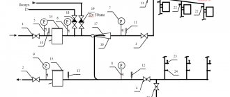
1-boiler, 2-heating heater branch, 3-boiler pressure pipe, 4-air exhaust pipes, 5-expander, 6,7 - heating branches of the compartment and corridor sides, 8-heating pipes, 9-circulation pump.
With a combined (electric-coal) heating system (Fig. 1), the water in the boiler is heated by high-voltage heating elements located in the water jacket, and in the absence of electricity - due to the heat of the burned solid fuel - coal).
The heating elements are powered via a single-wire train line with a rated voltage of 3000V direct or single-phase alternating current with a frequency of 50Hz along the route from locomotives, and at layover points from stationary devices. Various types of carriages are equipped with a water heating system with a combined boiler. This system consists of a boiler with an expander and optimal appliances.
High-voltage electrical equipment of passenger cars
The high-voltage electrical equipment of passenger cars is powered from the contact wire, through the locomotive pantograph, jumpers (pinches) of the high-voltage main and high-voltage undercar boxes.
If the contact network contains direct current with a voltage of 3000 V, then the boilers are powered directly by it. If the contact network contains alternating current with a voltage of 25,000 V, then a power take-off transformer is installed in the locomotive, which reduces this voltage to 3,000 V, and the boilers are heated by alternating current.
High voltage heating socket
Idle high voltage heating socket
After testing the brakes, the PEM and the driver approach the first car. The PEM connects the car jumper to the locomotive using a special heating key.
To connect the main lines of individual cars to each other into a common main line, it is necessary to sequentially connect all cars to the locomotive. To connect the lines, the pin of one car is inserted into the socket of another car, and the pin of the second car is inserted into the socket of the first car. In this case, two inter-car high-voltage connections are formed between each two cars.
After this, the heating key is handed over to the driver. Further activation of the heating is carried out from the locomotive cabin.
Construction of the boiler and heating element.
The combined heating boiler has the following design. The water jacket of the boiler is made somewhat wide, and 24 | high-voltage heating elements that are mounted on a flange ring. The heating element flange is attached to the ring using two studs with nuts and petal washers. Three insulators are located above the boiler firebox, to which three wires are connected in the pipelines that supply the heating elements.
High-voltage heating elements are covered with a protective casing. A low-voltage interlock in the form of a limit switch is installed on the protective casing, breaking the circuit of the high-voltage contactor coils when the bolts are disconnected and the casing is lifted under high voltage.
When the casing is securely fastened in the lower position, the bolt presses on the limit switch shank, preparing the switching on of the high-voltage contactors. To inspect the elements, the casing is lifted up, having previously unscrewed the bolts, and secured with safety chains.
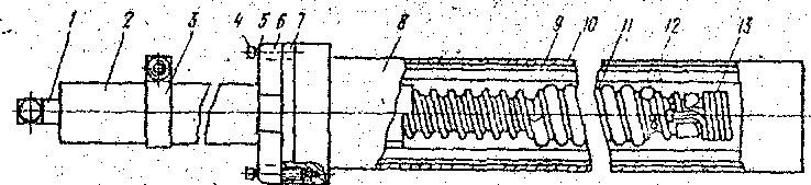
The high-voltage heating element is made in the form of a steel cylinder. The spiral 12 on a hollow ceramic rod 11 is connected at one end to a bracket 3 mounted on an insulator 2, and at the other end to a return wire 13 passing inside the rod to clamp 1. Insulation of current-carrying parts from the steel body 8 is carried out by a quartz sleeve (glass) 10, an insulator 2 and a ceramic flange 6 with a rubber gasket 7. Flange 6, made together with a ceramic rod 11, is attached to the heater body
bolts 4 with washers 5.
Heat from the coil is transferred to the water through the air surrounding it, the quartz glass, the graphite shell 9, which serves to improve heat transfer, and the heater body. The graphite shell also protects the quartz glass from damage.
that
Each heating element is designed for a voltage of 500 V. In the boiler, the heating elements are assembled sequentially into subgroups of 6 pieces. 2 subgroups are connected into groups in parallel.
Maintenance of heating systems of carriages
Before carrying out maintenance work on the heating system fittings, the coolant (water) is drained. If there is antifreeze in the heating system, it is not drained from the system. The heating system head drains are located in the boiler compartment and the corridor opposite the service compartment. To drain the coolant, you need to fold back the casing, attach a hose of the appropriate diameter, remove the heating panel by unscrewing the four screws, and open the corresponding taps.
The heating boiler, expansion and reserve tanks are washed and inspected. Failed heating elements, paronite gaskets, and defective bolted connections are replaced with new ones. Loose bolted connections are tightened. The outside of the heating pipes is cleaned of dust and dirt, and the intercostal spaces of the finned pipes are washed. Damaged heating pipes are repaired by welding or faulty elements are replaced with new ones. All openings for pipelines in the floor and walls of the boiler room must be sealed. The serviceability of manual and electric circulation pumps is checked in working order and faults are eliminated. The taps and valves of the heating system are inspected, checked for tight closure and operation without jamming, and any detected faults are also eliminated. If necessary, faulty car fittings are dismantled, disassembled and repaired. Gland and flange seals with traces of leaks are replaced. Faulty remote thermometers, sensors - temperature relays and liquid switches located in the boiler compartment are replaced with new ones.
Before filling the heating system with coolant, you must make sure that the drain plugs of the hand pump, the corresponding valves and taps are closed; You should also check the presence of the O-ring in the filling head. The system is filled with coolant through a filling pipe with a valve through the filling head.
The air from the system must be released through the air pipes into an expansion tank connected to the reserve tank, and a water test valve, which must be closed when coolant appears.
During filling, it is necessary to monitor the coolant level in the system. After the coolant appears from the overflow pipe, you need to continue filling until the reserve tank is filled to 1/3 of its volume (mark on the water meter glass). Then turn off the coolant supply and close the tap.
Temperature
The maximum permissible water temperature of the heating system is no more than 95 degrees. If its level rises above permissible standards, then the dust that settles on the lower level of the pipes will burn.
The boiler has two devices installed that monitor the operation of the heaters and their temperature conditions. If the temperature in the boiler equipment rises above the permissible norm, the thermostat blocks the heaters and they turn off.
We recommend: Types of combined heating systems for a private home
YouTube responded with an error: The request cannot be completed because you have exceeded your quota.
- Related Posts
- Types of combined heating systems for a private house
- How to choose a collector for a combined heating system?
Features of servicing heating and cooling systems of restaurant cars model 61-4189.
On restaurant cars model 61-4189, a 50% solution of propylene glycol is used as a coolant. When a restaurant car arrives at TO-3, the heating and cooling system is inspected to identify possible leaks from the coolant pipelines. If the coolant level is insufficient, the “Hydraulic system low level” light on the control panel in the service compartment lights up. If there are leaks, the coolant is drained from the entire system or only from the area to be repaired. Wherein:
- you need to make sure that the drain plugs of the hand pump and the corresponding taps are closed, and also check for the presence of the O-ring in the filler neck;
- the system is filled with coolant through a filling pipe with a tap through the filling neck using a hose with yellow connecting heads located in the supplied spare parts and accessories car located in the boiler compartment;
- when refueling, it is necessary to connect one end of the hose with a filling head to the filling head located in the boiler compartment above the spare tank hatch on the vestibule wall, and bring the other end out through the open vestibule door to connect to the inlet hose of the coolant container;
- remove the cover from the spare tank hatch and open the tap;
- air from the system is released through air pipes into an expansion tank connected to a reserve tank and a water tap, which is closed as soon as coolant appears in it;
- during filling, it is necessary to monitor the coolant level in the system; after the coolant appears from the overflow pipe, continue filling until the reserve tank is filled to 1/3 of the volume (mark on the water meter glass), after which stop filling by turning off the coolant supply and closing the tap;
- To avoid the coolant pouring out onto the floor of the boiler compartment, it is necessary to disconnect the second end of the hose from the filling hose and only after draining the remaining coolant from the hose and the filling pipe into a separate container, disconnect the hose from the filling neck. The system is delivered by a hand pump from a spare tank.
The heating system can be refilled with coolant from an external container through a plug installed between the hand pump and the reserve tank.
5.4.2 Water supply system
The water supply system of passenger cars is the most important sanitary equipment that provides the necessary conditions for passengers during their long journey. Regardless of the type, each passenger car is equipped with a gravity water supply system designed to provide passengers with drinking water, meet their domestic needs and replenish the heating system between refueling. In carriage building, two water supply systems for passenger cars have been used: domestic and those built by German factories.
The domestic water supply system (Fig. 5.13) with a total capacity of 1000 liters provides hot and cold water to all consumers of the car. The cold water supply system consists of a large 77 and a small 4 tanks with 5 trays, united by a two-inch pipe, filling pipes with connecting heads located under the car on both sides, and a network of pipelines (shown in the diagram as solid lines) with a variety of fittings.
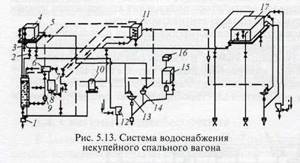
Large tank 17 with a volume of 850 liters is located above the ceiling of the toilet and the corridor of the non-brake end of the car. It consists of a steel body, breakwaters and a cover. Two filling pipes and a guide pipe are welded into the body, limiting the water level in the tank. The ends of the tank are equipped with hatches designed for cleaning it. Small tank 4 with a volume of 80 liters is located above the ceiling of the toilet and the corridor of the brake end of the car. It consists of a steel body, a cover and is equipped with an inspection hatch, an air pipe and a water meter glass. The inner surface of the large and small tanks is galvanized, and the outer surface is painted with enamel. The pallets are made of galvanized steel sheets and have a drain under the car. The drain pipes are equipped with heaters located at their ends. Valves are installed on the filling pipes to prevent water from splashing out of the tank while the car is moving. The heads of the filling pipes are covered with casings that protect them from contamination and are equipped with electric heaters. The water level in both tanks, connected to each other by an equalizing pipe, is determined by a water meter glass installed on a small tank 4. From the tanks, cold water flows to the boiler 10, the water box of the heating system, to the toilets, washbasins 13 and toilets 12, as well as to the service compartment for sink 14.
The hot water supply system consists of a hot water stove 8, an expansion tank b located in the boiler compartment, as well as a hot water tank 11 located above the ceiling of the corridor at the boiler end of the car, and a hot water pipeline system (shown in the diagram with dotted lines). Hot water tank 11 with a volume of 45 liters consists of a steel body covered with thermal insulation, a lid, a coil and a pipe. To periodically monitor the water temperature, a thermometer with a remote temperature indicator is built into the tank. The surface coating of the hot water tank body is similar to that of cold water tanks. Expansion tank b consists of a housing, an overflow pipe that prevents water from rising above a set level, a water pipe and pipes for connecting various pipelines. To control the water supply system of the car, valves 2, 7 and taps 3 are used.
The system under consideration has two operating modes: winter and summer. In winter mode, when the boiler of the heating system is running, hot water flows directly from the boiler into the coil of tank 11. In summer mode, when the boiler is not working, hot water enters the coil from hot water stove 8. Before heating the hot water stove, and also when it is already heated, The water level in the expander is periodically checked by opening the water test valve, and, if replenishment is necessary, it is pumped up with a hand pump 9. Drinking water is boiled before use and enters the tank 16, and is cooled by a water cooler 15.
The water supply system in a passenger compartment car (Fig. 5.14) includes two interconnected tanks 13 located at the end of the car body. The total volume of the water supply system under consideration is 1050 liters. At the boiler end of the car there is a rinsing tank with a volume of 50 liters, into which water is supplied from large tanks through pipe 11. In this system, water is heated in a special boiler 1 by coil 2, connected by a system of pipes and taps to the heating boiler. The temperature of the water in the boiler is controlled using a thermometer 4. The system is filled with water through filling pipes 14 located at the non-boiler end of the car: one on the compartment side, and the other on the corridor side. At the ends of these pipes there are connecting heads used to connect inlet hoses, protected by casings. In winter, before filling the system, electric heaters are turned on in advance to defrost the filling pipe heads.
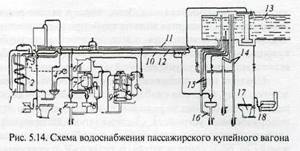
If the system is filled with one pipe 14, the other and pipe 16 are sentinel pipes that do not allow the set level to be exceeded. When the filling of the system is completed, a white signal light lights up in the middle part of the body on the electrical panel mounted on the side wall, after which the filling stops, and the signal installation switch on the distribution board of the service compartment is set to the “off” position. The main pipeline 11, running along the car, supplies boiler 9 with cold water through a filter and a float chamber, and the heating system through a check valve. Boiled water from boiler 9 is pumped by hand pump into tank 6, from where it enters tank 7 of the cooling unit. Water cooled to +(12-18) °C is supplied through a pipeline to a drinking water tap installed in a niche in the corridor wall at the boiler end of the car. Wash bowls 5 located at both ends of the car, as well as sink 8, are supplied with cold and hot water. Toilets 17 receive cold water from the cold water supply system, but for defrosting in winter, hot water is supplied to them through pipeline 18 from the heating system. To connect the hose used when cleaning the toilet, a pipeline 3 with a valve is provided. Hot water to washbasins 5 and sink 8 is supplied through pipeline 72, and returned to the unused hot water boiler through pipeline 10. The water level in tanks 13 is checked using control tubes 15 and taps installed in the toilet of the non-boiler end of the car.
Passenger cars of other types, such as dining cars, mail cars, luggage cars and others, are also equipped with a gravity water supply and heating system and differ from those discussed above in design solutions determined by the purpose of the car. In the dining car, for example, two independent hot and cold water supply systems are installed: the first for the kitchen with a dispensing compartment, the second for the boiler room with a toilet compartment. To supply the kitchen with cold water, there is a tank with a capacity of 800 liters located above the kitchen ceiling. From the tank, cold water is supplied through pipes to the taps: the sink located in the dispensing room, the sink and washbasin located in the kitchen. From the same tank, water is supplied through a pipeline by a hand pump to a water heater and a hot water tank, the volume of which is 50 liters. From here the water flows through the purification filter to the taps of the dishwashers and washbasin.
Both cold and hot water systems of the kitchen and dispensing room are filled through connection heads located in the middle of the car on both sides of the body. The water filling system of the entire car is equipped with an electric alarm for filling the tanks. When the filling of the system comes to an end, the light on the panel lights up, which goes out when filling stops. The filling pipes and the washbasin drain pipe have electric heaters. The water supply in the dining car for the boiler room and toilet is 130 liters. Cold water is supplied through a pipeline to the heating boiler, to the washbasin and shower. Hot water from the water heater flows through the pipeline through natural circulation into the hot water tank and returns back to the water heater. Hot water is consumed in the toilet, shower and washbasin.
The water supply system for baggage and mail cars also has hot and cold water. The cold water supply system consists of a tank with a capacity of 300 liters, located above the corridor in the niche of the service compartment, as well as pipelines and water dispensing devices. The system is filled with water from below from under the car through filling pipes running in the corridor and the baggage dispenser compartment. The shower is supplied with hot water from the boiler expander, and the toilet is supplied from the heating system. On some models of mail cars, a 25 liter electric heater is installed to obtain hot water. Drinking water in passenger cars is prepared in continuous boilers (Fig. 5.15) with combined electric coal heating. It consists of a housing U, a coal heating firebox 21, electrical elements: top 33 and side 27, a water collector 32 for boiled water, a float chamber 18 with a valve 16, a filter 9, a boiled water level indicator 30, a thermometer 19 and fittings: three-way 7, water folding 20 and 22 drain valves.
The space between the outer wall of the boiler body 1, the furnace body 21 and the conical pipe 31 of the water collector is filled with raw water. The inner wall of the boiler body and the conical pipe form a water collector 32 of boiled water, which is connected to the atmosphere by a drain pipe 3. Water from the water supply network enters the boiler through a three-way valve 7 and filter 9, a float chamber 18 and a valve 22.
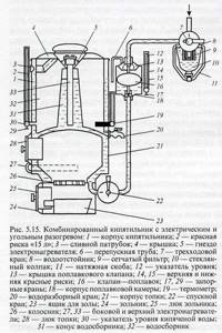
When water is heated to boiling point, it flows through cone 31 into the water collector 32, its level in the raw water chamber and the float chamber decreases, the float 16 lowers and opens the water supply valve. Thus, raw water replenishes the boiler, its level rises and the float closes the water supply with its upper shut-off needle. The float is adjusted so that the level of raw water cannot rise above the level that does not reach 40 mm from the upper edge of the cone 31, as a result of which the possibility of it entering unboiled form into the reservoir 32 is excluded. The level of raw water is controlled by the level indicator 12 of the float chamber, on which two red marks 14 and 15 are applied. The upper mark indicates the maximum filling of the boiler with water, and the lower mark indicates the maximum possible consumption of raw water and its minimum permissible level in the chamber. The filling of the reservoir with boiled water is controlled by the level 2 indicator, which also has a red line indicating the maximum filling of the reservoir. The productivity of the boiler during normal operation is 1.1-1.4 liters of boiled water per minute.
The installation for cooling drinking water (Fig. 5.16) consists of a compressor 18, a discharge valve 20, a condenser 16, a receiver 13, a shut-off valve 12, a filter 11, an automatic control valve 10 and an evaporator 8. Boiled water from tank 4 enters tank 6, is cooled in it and then supplied to the water tap 2.
The water is cooled by transferring its heat to the refrigerant vapor in the evaporator 8. The process of operation of the refrigeration unit is as follows. From the compressor 18, the gaseous refrigerant through the discharge valve 20 enters the condenser 16 and turns into a liquid state. From the condenser, through the receiver 13, shut-off valve 12, filter 11 and automatic control valve 10, the compressor 18 is pumped into the evaporator 5. When passing through the control valve 10, the liquid refrigerant expands, its pressure drops sharply and it goes into a gaseous state - it evaporates.
During the evaporation process, the refrigerant takes heat from the water, and then its vapors are sucked in by the compressor 18 through the suction valve 19, and the cycle repeats. The water cooling temperature level is set using thermostat 7 and can be adjusted within +(12-20) °C. The water cooler is located in a cabinet where there is a tank 4 for boiled water with a capacity of 40 liters, a tank for chilled water 6, a refrigeration unit 17, and in a niche 1 tap 2 for water distribution.
To remove air from the heat exchanger, you must:
- close all valves at the inlet of the heat exchanger;
- turn on the electric pump of the cooling system;
- open the tap at the first heat exchanger from the brake end of the car for 3*4 minutes;
- open the tap on the second heat exchanger and close the tap on the first and so on for all ten heat exchangers;
- pumping time for each heat exchanger is 3*4 minutes. In this case, it is necessary to monitor the level of propylene glycol in the reserve tank of the cooling system. When the propylene glycol level drops below the marks on the inspection hatch of the tank, it is necessary to replenish it.
During filling, it is necessary to monitor the coolant level in the system. After the coolant appears from the overflow pipe, continue filling the reserve tank to the mark (150mm from the bottom of the tank), then stop filling by turning off the coolant supply and closing the tap.
The cooling system is refilled using an electric pump from the spare tank of the cooling system through a filter and a check valve, which prevents coolant from overflowing through the tank.
Operation of water heating
At the stage of preparing the car for a trip during the heating period, if the car has water or combined heating, the conductor is obliged to check the condition of the boiler, the position of all valves and throttle valves, the presence of grates in the firebox, the serviceability of pumps and measuring instruments, the presence of water in the system and the absence of leaks, availability of technical documentation, as well as equipment.
Heating of the cars begins at an outside air temperature of 100 C or lower. The boiler is lit with paper and finely chopped wood. As the wood burns, the firebox is loaded with fuel evenly along the grate. In this case, the firebox door should be closed and the ash pan door should be open. The intensity of fuel combustion is regulated by the amount of air supplied to the firebox through the ash pan door. To increase draft and air flow, open the ash pan door, and close it to reduce it. The recommended thickness of the fuel layer for large pieces of coal is 100-200 mm, for small pieces 50-100 mm. For better fuel combustion, punctures of fuel and slag are periodically made with a lance. Ash and slag should not be allowed to accumulate along the perimeter of the grate at the point of contact with the fire box casing, as they create a significant obstacle to heat transfer. While firing the boiler, it is necessary to maintain constant combustion of the fuel and the required water temperature in the boiler. It is necessary to systematically monitor the water level in the heating system using a hydrometer or control tap, pumping up water if necessary.
To avoid steam formation and the associated loss of water and deterioration of its circulation, the conductor must monitor the thermometer to ensure that the water temperature in the system does not exceed 900 C. At higher temperatures, the ash pan lid should be closed.
At low outside temperatures, the heating of the car is accelerated using a manual circulation pump at a water temperature in the boiler of at least 500 C. Before passengers board the car, it must be warmed up to a temperature of 18 -200 C.
If dark spots form on the surface of the fuel, gradually covering the entire surface of the grate, the furnace boiler should be cleaned. It is recommended to clean the firebox in three stages: rake the entire hot layer of fuel to one side, lift the slag with a peak, after removing the flue gases, put it in a bucket, remove the ash through the holes of the grate into the ash pan; move the hot layer of fuel onto the cleaned surface of the grate and also clean its second part; level the hot layer of fuel and load the firebox with fresh coal, scrape the ash from the ash pan into a bucket. The boiler firebox should be cleaned quickly, without waiting for it to cool down.
At the point of formation and turnover, it is necessary to clean the firebox and ash pan from ash and slag and keep the boiler in working condition. After the heating season, for safety reasons, the heating system must be filled with water. During operation, periodically, but at least once a day, and when filling the heating system with water, it is necessary to release air through the air bleed valves.
In winter, when outside temperatures are above zero, the cars on all trains are supplied with fuel at the formation and turnover points up to the full capacity of the coal boxes.
Features of maintenance of cars with electric and combined heating
In accordance with the rules of the International Union for Passenger and Baggage Cars, alternating current with a voltage of 1500 V with a frequency of 50 Hz and direct current with a voltage of 1500 and 3000 V can be used for electric heating of cars. On domestic roads, electric heating operates at a voltage of 3000V direct or alternating single-phase current with a frequency of 50Hz. When operating on direct current, electric heating receives power without conversion from the electric locomotive through inter-car electrical high-voltage connections and the under-car main line.
When operating on an alternating current voltage of 25 kV with a frequency of 50 Hz, the alternating current in the main transformer of the electric locomotive is converted into alternating current with a voltage of 3000 V with a frequency of 50 Hz. For high-voltage equipment of cars, the type of current does not matter.
When transmitting electrical energy for heating, inter-car electrical connections are installed on each car, including a plug, a socket - socket and an idle receiver (solid socket). The plug and socket serve as connecting elements of the high-voltage train main line. The hole for the plug in the socket is covered with a cover, which is locked with a locking lock. You can open the cover and insert the plug into the socket only after opening the lock with the heating key. When the lid is open, the key cannot be removed from the socket. Similarly, use the key to open and lock the idle plug receiver.
If a train breaks en route, the electric locomotive driver must remove the voltage from the heating main and, together with the train electrician, ensure that the heating main is disconnected from the electric locomotive.
In the event of a fire, the crew servicing the carriage and the electric locomotive driver must act in accordance with the Instructions for ensuring fire safety in passenger train carriages and the Instructions for ensuring fire safety on locomotives and multiple unit rolling stock.
The timing for heating a train from an electric locomotive (connecting the train to an electric locomotive) is set on most roads from September 5 to May 15.
Checking the completeness and serviceability of electrical equipment of cars and electric locomotives in preparation for winter transportation should end 20 days before the heating season.
During the heating season, during TO-1, grounding shunts are inspected. The plugs of the head and tail cars are removed from the idle receiver and inspected. The locking mechanisms are checked with a heating key.
Inter-car connections of other cars are checked without disconnection. Open boxes with electrical equipment and inspect electrical devices. Check the connections of visible grounding shunts on combined heating boilers and protective covers of electric furnaces. Electric or combined heating systems are checked for the functioning of control and alarm devices. Measurements are taken of the electrical insulation resistance of the main line of each car, which must be at least 20 MΩ, and for a train of up to 24 cars - at least 1.2 MΩ.
1 hour before the train departs from the technical station, the train is connected for heating to a stationary installation or electric locomotive. During heating, the functionality of the electric heating is checked based on the temperature conditions in the cars. The air temperature in the cars should be 18 - 220 C.
At inspection points, train electricians check the condition of the inter-car connection of the head car, inspect electrical equipment and check the operation of the electric or combined heating system.
Maintenance of high-voltage electrical equipment of trains with a turnaround of up to three days is carried out at the formation point after 6 days.
In operation, the electrical equipment of the heating installations of carriages must operate only in automatic control mode.
Each passenger train formed from cars with high-voltage combined or electric heating must have only one of the heating keys to test the devices.
It is prohibited to connect to an electric locomotive for heating more than the number of cars specified on the body of the electric locomotive.
In the driver's route, the train electrician indicates the actual number of heated cars in the train. When a passenger train is prepared for a trip, the personnel responsible for its preparation must be given the readiness to supply high voltage to it. After connecting the heating line of the train, the driver lifts the pantograph, inserts the heating key into the socket on the control panel and turns it - a warning lamp lights up on the front panel of the distribution cabinet, indicating that the train is under voltage of 3000V.
Heating devices
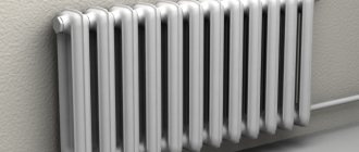
These include low-voltage heating electric furnaces (located under radiator casings), electric heaters (located in the ventilation duct), electric boilers, electric stoves (in the boiler room).
All heating devices must be turned on in strict accordance with the operating rules. It is forbidden to hang rags or rags on them for drying. No foreign objects should come into contact with them. When operating heating devices, the conductor is prohibited from leaving the carriage. In addition, they cannot be turned on when the car is powered from the battery, when the generator is faulty, or when power is supplied to an adjacent car.
Relieving the voltage and disconnecting the heating line of the train is carried out in the reverse order.
After connecting the train to the AC electric locomotive, the driver must start the auxiliary machines and then turn on the train heating. After connecting the heating main, the conductors must set the control panel switch to automatic heating mode. Before disconnecting the heating main from the power supply, it is necessary to disconnect the devices of the cars.
If there is voltage on the train, it is prohibited to carry out maintenance work on electrical equipment and it is prohibited to wash floors when there is high voltage on electric stoves. Wet wiping is allowed when the ovens are on. On carriages with combined heating, wet cleaning of floors is allowed, except for the boiler room, without disconnecting the electrical circuits of the combined heating boiler.
On electrified sections of the track, train crew workers are prohibited from climbing onto the roof of the car for any work. The ladder to reach the roof must be locked and sealed.
When the heating system protection elements are triggered, the driver is allowed to turn it on once. In the event of repeated activation of the protection, subsequent activation can be made after identifying and eliminating the cause of the operation.
In the event of damage to the heating main of a train with combined heating, depending on the location of the damage, the train or group of cars is transferred to coal heating; depending on the location of the damage, the train or group of cars is transferred to coal heating. To turn on the heating of the train on electric locomotives, there must be repair keys in the depot where the electric locomotives are registered.
The heating key must be marked with the road code, the depot number and the serial number of the key. To record keys in the depot, a book is kept for their issuance and receipt. It is prohibited for persons servicing high-voltage heating and locomotive crews to have and use other keys and devices for opening inter-car connections and boxes with equipment.
The heating line of the head car and the electric locomotive is connected and disconnected by the train electrician in the presence of the driver with the key to the electrical control circuits of the electric locomotive. In this case, the current collectors on the electric locomotive must be lowered. After connecting the train heating line to the electric locomotive, the train electrician gives the key to the driver; After disconnection, the key remains with the train electrician.
When the number of cars in a train is up to 20 units, the heating main is connected by one inter-car connection, and with a larger number of cars in a train, by two. All operations on connecting and disconnecting the head car with the electric locomotive must be carried out by the electrician wearing rubber gloves.
The heating line of the train in the inter-train standby is connected and disconnected from the stationary heating point by car depot workers authorized to service high-voltage electrical equipment, together with the train electrician or the train manager.
During the heating of the train from a stationary electric heating point, the conductors are in the cars.