4.1. Upon completion of installation work, installation organizations must carry out:
testing heating systems, heat supply, internal cold and hot water supply and boiler rooms using the hydrostatic or manometric method with drawing up a report in accordance with the mandatory Appendix 3, as well as flushing systems in accordance with the requirements ï. 3.10 of these rules;
testing of internal sewerage and drainage systems with drawing up a report in accordance with the mandatory Appendix 4;
individual tests of installed equipment with drawing up a report in accordance with the mandatory Appendix 1;
thermal testing of heating systems for uniform heating of heating devices.
Testing of systems using plastic pipelines should be carried out in compliance with the requirements of CH 478-80.
Tests must be carried out before finishing work begins.
Pressure gauges used for testing must be calibrated in accordance with GOST 8.002-71.
4.2. During individual testing of equipment, the following work must be performed:
checking the compliance of the installed equipment and the work performed with the working documentation and the requirements of these rules;
testing equipment at idle and under load for 4 hours of continuous operation. At the same time, the balancing of wheels and rotors in pump and smoke exhauster assemblies, the quality of the stuffing box packing, the serviceability of starting devices, the degree of heating of the electric motor, and compliance with the requirements for assembly and installation of equipment specified in the technical documentation of the manufacturers are checked.
4.3. Hydrostatic testing of heating systems, heat supply systems, boilers and water heaters must be carried out at a positive temperature in the premises of the building, and cold and hot water supply systems, sewerage and drains - at a temperature not lower than 278 K (5 ° C). The water temperature should also not be lower than 278 K (5°C).
INTERNAL COLD AND HOT WATER SUPPLY SYSTEMS
4.4. Internal cold and hot water supply systems must be tested by hydrostatic or manometric method in compliance with the requirements of GOST 24054-80, GOST 25136-82 and these rules.
The test pressure value for the hydrostatic test method should be taken equal to 1.5 excess operating pressure.
Hydrostatic and pressure testing of cold and hot water supply systems must be carried out before installing water taps.
Systems are considered to have passed the tests if, within 10 minutes of being under test pressure using the hydrostatic test method, no pressure drop of more than 0.05 MPa (0.5 kgf/cm2) and drops in welds, pipes, threaded connections, fittings and water leaks are detected through flushing devices.
At the end of the hydrostatic test, it is necessary to release water from the internal cold and hot water supply systems.
4.5. Manometric tests of the internal cold and hot water supply system should be carried out in the following sequence: fill the system with air at a test excess pressure of 0.15 MPa (1.5 kgf/cm2); if installation defects are detected by ear, the pressure should be reduced to atmospheric pressure and the defects eliminated; then fill the system with air at a pressure of 0.1 MPa (1 kgf/cm2), maintain it under test pressure for 5 minutes.
The system is considered to have passed the test if, when it is under test pressure, the pressure drop does not exceed 0.01 MPa (0.1 kgf/cm2).
REQUIREMENTS FOR BASIC TEST METHODS
2.1. Hydrostatic method
2.1.1. The method is carried out using a compressor method, both with and without the use of indicator masses applied to the controlled surface. Description of the method - according to GOST 24054-80.
2.1.2. When testing, the connection must be completely bled of air before increasing pressure. If, during water strength tests, the connection was filled with cold water and dew appeared on its walls, then leak tests should be carried out after it has dried.
2.1.3. The test pressure during testing is determined by the formula:
where is the conditional pressure (excessive pressure that the connection can withstand at normal temperature of the working environment under operating conditions);
— coefficient depending on the conditional pressure is determined from the table.
2.1.4. During testing, a gradual and smooth increase and decrease in pressure must be ensured. Do not tap the connection under pressure. If drops, spots and (or) a sharp drop in pressure are detected, the tests are stopped and the connections are inspected to determine the causes of the defect.
2.1.5. The test time for one connection using the hydrostatic method is at least 3 minutes.
2.2. Manometric method
2.2.1. The method is implemented in the following ways: compression, vacuum, chamber, blowing and comparison with the flow from a calibrated leak.
2.2.2. Descriptions of compression, vacuum and chamber methods - GOST 24054-80.
2.2.3. Tests using the blowing method are carried out in the following order:
evacuate the internal cavity of the connection;
take the pressure gauge reading;
blow the joint joint with a test gas, after which the pressure gauge reading is taken again, and the change in pressure is determined using the formula
where is the sensitivity of the pressure gauge with respect to the test gas;
- reading of a pressure gauge calibrated in air;
— pressure gauge reading taken after blowing with test gas.
The leakage of the connection is judged by the magnitude of the pressure change.
Note. It is recommended to use a test gas that satisfies the following inequality
where is the speed of the pump when pumping air and test gas from the connection;
— flow of air and test gas through the joint;
— sensitivity of the pressure gauge in relation to air.
2.2.4. Tests by comparison with the flow from a calibrated leak are carried out in the following order:
the internal cavity of the connection is evacuated until the pressure in it reaches a fixed value;
apply a test gas to the leak and, changing its pressure, select such a flow through the leak so that the vacuum gauge shows the same value;
using the graph attached to the calibrated leak certificate, determine the flow corresponding to this pressure;
Leakage is judged by the flow rate.
2.2.5. When testing using the vacuum method, it is necessary to determine, based on the pressure gauge readings, the moment in time when the pressure in the internal cavity of the connection begins to change linearly, and then, after a period of time, measure the pressure in the internal cavity of the connection. The flow through the joint is calculated using the formula
where is the pressure inside the connection at the moment of time;
— pressure inside the connection at the moment of time;
— volume of the internal cavity of the connection.
Note. In connections with large gas emissions, it is advisable to connect the pressure gauge through a cooled trap.
2.2.6. It is recommended to estimate the permissible pressure drop when testing using the compression method using the formulas given in Reference Appendix 1.
Note. If a pipeline or a section of a pipeline where the working medium is liquid is tested using the compression method, then the ratio of gas pressure to the working pressure of the liquid should not be lower than 0.1.
2.2.7. The temperature error in determining the change in pressure inside a connection or chamber is estimated using the formula
where is the test gas pressure;
— absolute gas temperature;
— change in temperature during measurement.
2.3. Bubble method
2.3.1. The method is carried out in the following ways: compression, vacuum, soaping.
Description of methods - according to GOST 24054-80.
2.3.2. If water is used as an indicator liquid, then to increase its transparency, aluminum-ammonium alum is added at the rate of 500 g of alum per 3 m of water, after which the solution should be thoroughly mixed and kept for one and a half days.
2.3.3. If it is necessary to increase sensitivity, it is recommended to add a surfactant to the indicator liquid that does not have a harmful effect on the materials of the connection parts.
2.4. Mass spectrometric method
2.4.1. The method is carried out in the following ways:
vacuum chamber, pressure testing in the chamber, blowing, probe, accumulation, accumulation at atmospheric pressure, selective sampling of test gas.
2.4.2. Descriptions of methods of a vacuum chamber, pressure testing in a chamber, blowing, probe, accumulation at atmospheric pressure - according to GOST 24054-80.
2.4.3. It is recommended to carry out methods of a vacuum chamber and pressure testing in a chamber on installations, the diagrams of which are given in reference Appendix 2.
2.4.4. Tests using the accumulation method are carried out in the following order:
the test connection is evacuated, a zeolite pump is connected to it and the connection is kept under vacuum for a certain time, after which it is connected to a leak detector and the background flow of the test gas is measured;
place the connection in a chamber, fill it with a test gas or a mixture of gases containing a test gas, and hold it for a certain time, after which it is connected to a leak detector and the flow of the test gas is measured;
Leaks are judged by the difference in leak detector readings.
The recommended test setup is shown in Reference Appendix 2.
2.4.5. Tests using the method of selective sampling of test gas are carried out in the following order:
a test gas is supplied to the connection cavity;
connect the chamber to the leak detector through an element selectively permeable to the test gas;
The leakage of the connection is judged by the amount of test gas diffused through the element.
The recommended test setup is shown in Reference Appendix 2.
2.4.6. When tested using the blowing method, the speed of movement of the blower along the joint joint should not be higher than 1.5 mm/s.
2.4.7. When testing using the probe method, the speed of movement of the probe along the joint joint should not go beyond the range of 2...5 mm/s if the test gas is helium, and 0.5...2 mm/s if the test gas is argon.
2.4.8. The sensitivity threshold of leak detection equipment is in accordance with GOST 24054-80.
Note. The sensitivity threshold of the installation implementing a particular method may differ significantly from the sensitivity threshold of the equipment. Thus, when implementing the accumulation method, the sensitivity threshold of the installation is several orders of magnitude higher than that of the leak detection equipment included in this installation, and when implementing the probe method, it is several orders of magnitude lower.
2.4.9. Calibration of mass spectrometric leak detectors is carried out using a diffusion helium leak of the “Gelite” type in accordance with the description and operating instructions attached to each leak sample. As a result of calibration, the value of the scale division () of the leak detector output device is determined using the formula
where is the helium flow from the “Gelite” leak;
— steady reading of the leak detector from the “Gelit” leak;
— leak detector reading due to background helium.
2.5. Halogen method
2.5.1. The method is carried out using blowing and probe methods.
2.5.2. Descriptions of methods - according to GOST 24054-80.
2.5.3. The sensitivity threshold values for leak detection equipment are in accordance with GOST 24054-80.
2.5.5. The room in which the halogen method is tested must have supply and exhaust ventilation. The halogen content in it should not exceed 10%.
2.5.6. When testing using the blowing method, leak detectors with a vacuum sensor are used, while the probe method uses an atmospheric sensor.
2.5.7. Leak detectors with a vacuum sensor are calibrated using one of the following methods:
by changing the partial pressure of the test gas, for which a test gas is introduced into the internal cavity of the connection through the leak and the associated change in the leak detector readings is compared with the change in pressure recorded by the pressure gauge;
according to the flow of test gas through a calibrated diaphragm.
Note. The first method is recommended for connections pumped out at pressures less than 0.1 Pa, the second - for pressures greater than 0.1 Pa.
2.5.8. Leak detectors with an atmospheric sensor should be calibrated using a Halot halogen leak in accordance with the description and operating instructions attached to each leak sample. As a result of calibration, the division price () of the scale of the leak detector output device is determined according to the formula
where is the flow from the halogen leak;
— leak detector signal from this leak.
Note. Due to the fact that the sensor may lose sensitivity from long-acting portions of halogens, periodic checking of its initial current is necessary. To restore the sensitivity of the sensor, it requires long-term training at increased emitter heat and a clean air pressure of 10 Pa.
HEATING AND HEAT SUPPLY SYSTEMS
4.6. Testing of water heating and heat supply systems must be carried out with the boilers and expansion vessels turned off using the hydrostatic method with a pressure equal to 1.5 working pressure, but not less than 0.2 MPa (2 kgf/cm2) at the lowest point of the system.
The system is considered to have passed the test if, within 5 minutes of being under test pressure, the pressure drop does not exceed 0.02 MPa (0.2 kgf/cm) and there are no leaks in welds, pipes, threaded connections, fittings, heating devices and equipment.
The test pressure value using the hydrostatic test method for heating and heat supply systems connected to heating plants must not exceed the maximum test pressure for heating devices and heating and ventilation equipment installed in the system.
4.7. Manometric tests of heating and heat supply systems should be carried out in the sequence specified in clause 4.5.
4.8. Surface heating systems must be tested, usually using the hydrostatic method.
Manometric testing can be carried out at negative outdoor temperatures.
Hydrostatic testing of panel heating systems must be carried out (before sealing the installation windows) with a pressure of 1 MPa (10 kgf/cm2) for 15 minutes, while the pressure drop is allowed no more than 0.01 MPa (0.1 kgf/cm2).
For panel heating systems combined with heating devices, the test pressure value should not exceed the maximum test pressure for the heating devices installed in the system.
The test pressure value of panel heating systems, steam heating and heat supply systems during manometric tests should be 0.1 MPa (1 kgf/cm2). Test duration – 5 minutes. The pressure drop should be no more than 0.01 MPa (0.1 kgf/cm2).
4.9. Steam heating and heat supply systems with operating pressure up to 0.07 MPa (0.7 kgf/cm2) must be tested by the hydrostatic method with a pressure equal to 0.25 MPa (2.5 kgf/cm2) at the lowest point of the system; systems with a working pressure of more than 0.07 MPa (0.7 kgf/cm2) - hydrostatic pressure equal to the working pressure plus 0.1 MPa (1 kgf/cm2), but not less than 0.3 MPa (3 kgf/cm2) in the highest point of the system.
The system is recognized as having passed the pressure test if, within 5 minutes of being under test pressure, the pressure drop does not exceed 0.02 MPa (0.2 kgf/cm2) and there are no leaks in welds, pipes, threaded connections, fittings, or heating devices.
Steam heating and heat supply systems, after hydrostatic or pressure testing, must be checked by starting steam at the operating pressure of the system. In this case, steam leaks are not allowed.
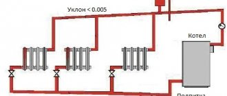
4.10. Thermal testing of heating and heat supply systems at positive outside temperatures must be carried out at a water temperature in the supply lines of the systems of at least 333 K (60 °C). In this case, all heating devices should warm up evenly.
If there are no heat sources during the warm season, a thermal test of heating systems must be carried out upon connection to a heat source.
Thermal testing of heating systems at negative outside air temperatures must be carried out at a coolant temperature in the supply pipeline corresponding to the outside air temperature during testing according to the heating temperature schedule, but not less than 323 K (50 °C), and the circulating pressure in the system according to the working documentation .
Thermal testing of heating systems should be carried out within 7 hours, while checking the uniformity of heating of the heating devices (to the touch).
BOILER HOUSES
4.11. Boilers must be tested using the hydrostatic method before lining work is carried out, and water heaters - before applying thermal insulation. During these tests, the heating and hot water supply systems must be disconnected.
Upon completion of hydrostatic tests, it is necessary to release water from boilers and water heaters.
Boilers and water heaters must be tested under hydrostatic pressure along with the fittings installed on them.
Before hydrostatic testing of the boiler, the covers and hatches must be tightly closed, the safety valves are jammed, and a plug must be placed on the flange connection of the flow device or bypass closest to the steam boiler.
The test pressure value for hydrostatic tests of boilers and water heaters is accepted in accordance with the standards or technical specifications for this equipment.
The test pressure is maintained for 5 minutes, after which it is reduced to the maximum operating pressure, which is maintained for the entire time required to inspect the boiler or water heater.
Boilers and water heaters are recognized as having passed the hydrostatic test if:
during the time they were under test pressure, no pressure drop was observed;
There were no signs of rupture, leakage or surface sweating.
4.12. Fuel oil pipelines should be tested with a hydrostatic pressure of 0.5 MPa (5 kgf/cm2). The system is considered to have passed the test if, within 5 minutes of being under test pressure, the pressure drop does not exceed 0.02 MPa (0.2 kgf/cm2).
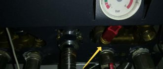
Stands for hydrotesting
Test stands for pipeline fittings are research equipment, which includes: a frame, a hydraulic system, instrumentation, and additional devices. Bench testing allows you to determine several characteristics simultaneously with high accuracy. It is impossible to carry out such tests in the field and with such a level of accuracy.
Such stands are adapted for testing fittings for strength, tightness, and functionality of devices. These testing complexes are in demand for:
- incoming inspection of purchased fittings;
- intermediate and final control at production enterprises producing reinforcing elements;
- inspections after repair activities;
- periodic monitoring of the functionality of safety valves.
Tests for the strength and tightness of the valve body are carried out under static loading with increased pressure. The working medium of the hydraulic system is water or oil.
INTERNAL SEWERAGE AND DRAINS
4.13. Testing of internal sewerage systems must be carried out by pouring water by simultaneously opening 75% of the sanitary fixtures connected to the area being tested for the time required for its inspection.
The system is considered to have passed the test if, during its inspection, no leaks were detected through the walls of the pipelines and joints.
Tests of sewer outlet pipelines laid in the ground or underground channels must be carried out before they are closed by filling them with water to the level of the ground floor floor.
4.14. Tests of sections of sewerage systems hidden during subsequent work must be carried out by pouring water before they are closed with the drawing up of an inspection report for hidden work in accordance with mandatory Appendix 6 of SNiP 3.01.01-85.
4.15. Internal drains should be tested by filling them with water to the level of the highest drain funnel. The duration of the test must be at least 10 minutes.
Drains are considered to have passed the test if no leaks are found during inspection and the water level in the risers has not decreased.