Air heating of premises: an excursion into history
If we look at the history of human development, we can confidently state that the first methods of heating a home were carried out using air: an open fire was lit in the cave. Then, with the advent of real housing, man began to create air heating systems.
The first written description of such a system (hypocaust) appeared in the 1st century BC. e. Its author was the Roman architect Vitruvius. Heating was carried out in two stages. A stove was laid out outside the room, hot smoke flowed through exhaust channels under the floor and into the walls. After the furnace went out, the smoke channels were closed. However, others opened, through which air came from outside, passed through the stove, was heated, and entered the home fresh and warm.
So it would be wrong to talk about creating modern, completely new air heating systems. The existence of such heating, and even with the use of ventilation, dates back many centuries. The hypocaust was a fairly expensive system, so it was available only to the rich.
The next significant era for the development of engineering dates back to the 15th century; it gave humanity the Russian stove. The air was in direct contact with the heated surface, reducing heat loss and increasing efficiency. The price of air heating has dropped significantly, and efficiency has increased.
Further, air heating systems were gradually modernized and improved. Furnaces began to be made not only from stone, but also from various types of metal. Pumps and fans began to be introduced into the systems, air purification and humidification were carried out. They began to use automation and electronic control.
System installation features
If the calculations are carried out at a high professional level, and the design of the cottage air heating system is drawn up, you can carry out the installation yourself.
For this you will need:
- heating device;
- air ducts;
- fan;
- gratings;
- fasteners;
- tool for working with air ducts, etc.
A gas generator is usually used as a heater as the most cost-effective option. Air ducts can have a rectangular, square, round or oval cross-section.
Typically, suitable designs can be ordered from a company that manufactures ventilation systems.
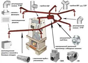
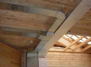
The diagram shows the elements of the air heating system, which will allow installation of air ducts in strict accordance with the design documentation
Typically, air ducts are made of galvanized steel; they are light enough so as not to overload the supporting structures of the house, and also have increased resistance to wear and corrosion. For rigid air ducts, you will need special elements that provide a slope of 45 or 90 degrees. But for flexible products such elements are not needed.
Air ducts are also made from ordinary steel, copper, plastic and other materials. There are even textile designs of this type. In places with high humidity, it is recommended to use copper elements as they are more resistant to such conditions.
Plastic structures are relatively inexpensive and can be used away from potential sources of fire.
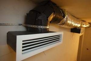
Air ducts are fixed under the ceiling and floor, as well as inside the walls. If there is a need to lay the air duct not inside, but along the wall, it is covered with a false panel. Ventilation grilles are installed in the ceiling and floor at the ends of the air ducts.
Rigid air ducts made of galvanized steel are very reliable and durable. For their successful installation, you will need elbows with a rotation angle of 45 and 90 degrees.
Air masses moving inside a structure can make some noise. To reduce this negative impact, it is recommended to hide the air ducts under a layer of sound insulation.
Typically, this material also has thermal insulation properties, which only increases the efficiency of the system.
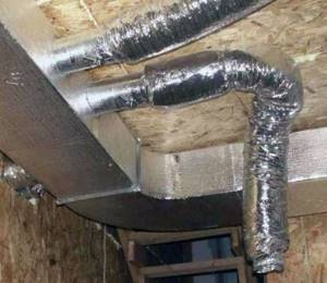
To ensure that air heating structures make as little noise as possible during operation, it is recommended to cover them with a layer of insulating material
It is worth considering the option of purchasing air ducts that already have such an insulating layer applied. This will simplify and speed up installation work.
If there is a need to install a fan, or several such devices, then it is usually included in the system next to the heater. The fan is supplied with power and also provides a backup source of electricity.
The system also includes one or more filters. These can be mechanical cleaning filters that prevent the spread of dust particles. Along with these devices, it is recommended to install a carbon filter that absorbs various odors. Of course, filters need to be cleaned and/or replaced periodically.
Part of the air duct is led outside to provide fresh air. This section is supplied to the filter system, and then the air is supplied to the heat exchanger of the heating device. If installation work is carried out during the construction of a house, then its implementation usually does not cause any great difficulties. The main thing is a good project.
To improve the microclimate in the house, useful elements such as an air humidifier, ionizer, ultraviolet sterilizer, etc. are built into the air heating system. These elements are not mandatory, but if funds allow, you should not refuse them.
Another useful device is a ducted air conditioner. It is also built into the air duct system. This will allow you to use the system in the warm season to cool the air in the room.
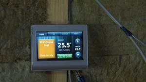
Automatic control systems significantly improve the operation of the air heating system and reduce heat costs, as well as simplify the operation of equipment
The final stage is connecting the automatic control system. You will need air temperature sensors in the rooms and a control panel with a processor that will process the received data and regulate the operation of the heating equipment.
Blade design features
Regarding the design features of the blades of the future generator, it should be noted that they should not be too long, and their total number usually does not exceed three. This choice is explained by the fact that the weight of the rotating elements in this case will be less, and the risk of their destruction is sharply reduced.
Note! A number of industrial designs use long and relatively heavy blades, but their design provides for a variable angle of inclination of the plane of rotation. This arrangement of the moving mechanism allows you to change the speed while simultaneously reducing the noise level
This arrangement of the moving mechanism allows you to change the speed while simultaneously reducing the noise level.
The approximate cost of the most inexpensive example of an industrial wind turbine with a power of up to 1 kW is about 50 thousand rubles. and more. For most users, this amount turns out to be absolutely unaffordable. This explains the desire of many of them to try to make a wind turbine on their own, taking advantage of the capabilities of an old, but still working self-generator.
Types and types of heat generators for air heating
Heat generators are equipment that provides direct production of coolant heated to the desired temperature. Heating occurs during the combustion of various types of fuel. Thermal generators are worthy competition to traditional boilers for heating a home.
Depending on the fuel used, air heating units are divided into the following types:
- Gas heat generators are considered the most common type, because such fuel is the most affordable, gas lines can be very branched, and the fuel does not need to be transported, loaded into the device and stored. Natural gas in our country is considered the cheapest type of fuel. If we compare gas by the amount of harmful emissions that are released during combustion, then they are much less than other types of fuel. The efficiency of gas heating equipment is the highest and is 91%. There are models with closed and open heat exchangers. The first type is safer, but also more expensive.
- Diesel heat generators run on kerosene or diesel fuel. They differ in the type of nozzle and are available with drip feed and spray. In the latter case, the fuel is evenly dispersed in the combustion chamber.
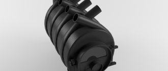
- Universal heat generators can operate on animal and vegetable fats, waste oil or diesel fuel. These devices are usually used in manufacturing plants that use oils and fats in the process. At the same time, the problem of recycling waste oils and fats is solved. Their power is slightly less than that of the previous variety. In addition, during the combustion of this fuel, slags are constantly formed that need to be removed. That is why such devices have two combustion tanks to ensure uninterrupted operation while cleaning one chamber of toxins.
- Solid fuel generators are a design that combines a traditional stove and diesel or gas appliances. The unit has a fuel loading door and grate bars. Wood shavings, wood chips, firewood, peat, coal and other waste (for example, buckwheat husks) are used as fuel. Their efficiency reaches 85%. The dimensions of these devices are significant. In addition, waste is generated during fuel combustion.
- Vortex heat generators use antifreeze or water during operation to convert electrical energy into heat.
Air heating options
So, our task is to heat the air masses and supply them to the premises of a country cottage or apartment. How to organize air heating:
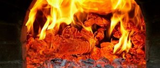
- From the fireplace, wood stove.
- Use VRF systems using freon. Simply put, inverter air conditioners, air source heat pumps.
- Install a combined boiler + chiller + fan coil air conditioning system.
- Organize centralized air heating (abbreviated as VO), combined with ventilation of a private house. Use an electric heater or a gas air-heating furnace as a heat source.
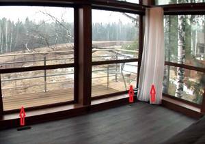
A veranda with a large glass area can be conveniently heated with hot air supplied from the floor
Reference. The latter option is often implemented in American and Canadian cottages built using frame technology. The heater is a gas oven.
For heating/cooling large production workshops, a slightly different scheme is implemented. There are 2 networks of air ducts built in the premises - supply and exhaust. Both converge to a ventilation unit - a central air conditioner, consisting of the following blocks:
- 2-3-stage filters purify air masses before being supplied inside the building and emitted outside;
- heat exchanger-heater No. 1 heats the flow using hot water from the boiler room;
- heat exchanger No. 2 serves to cool the air and works in conjunction with a chiller;
- a plate cross (or rotary) recuperator removes heat from the exhaust flow and transfers it to the supply flow, saving 50...80% of energy;
- humidification unit;
- Centrifugal fans force flows through sections of the central air conditioner and further along the air ducts.
Why did we describe the design of an industrial climate control system? So that you immediately understand: installing full-fledged air heating + ventilation + cooling is not an easy and expensive task. But, as the owner of a country house, you can consider all heating methods, choose the simplest and cheapest, or return to the water scheme - heated floors, radiators.
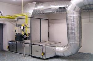
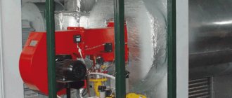
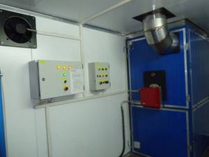
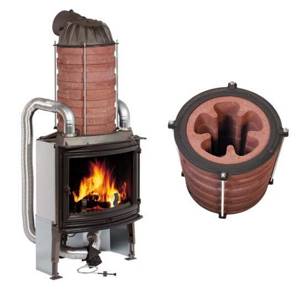
Industrial series heating system running on natural gas
Direct air heaters
Direct air heaters are based on the principle of heating a room with red-hot porous ceramic tiles emitting infrared radiation, in the depths of which natural gas is burned. These are nothing more than gas fireplaces, near which it is pleasant to spend time, basking in the flow of radiant energy. Usually these are relatively inexpensive devices with a power of 3-4 kW, the production of which has been mastered by some manufacturers of heating devices (about the selection and placement of heating devices).
The biggest disadvantage of heating devices of this type is that oxygen “burns out” in heated rooms, and gas combustion products remain in the room. Therefore, such devices serve more for decorative purposes and cannot be recommended as the main source of heat.
Indirect air heaters
The above disadvantages can be partially or completely avoided by using indirect air heaters. This equipment is a convective-radial heat exchanger and heat exchangers with a built-in combustion chamber. When heated, the air becomes lighter and rises, and in its place comes cold air, which heats up, etc. (picture 1). Thus, the idea of a convector that warms a room without using forced air circulation devices arose.
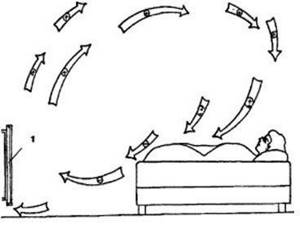
Figure 1. Convector air exchange in the room: 1 - convector; (+) - warm air; (+/-) — cooling air; (-) - cold air.
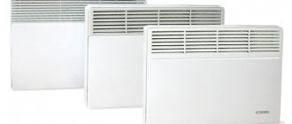
Gas convectors and heaters
Gas convectors are independent heating equipment that represents a real alternative to traditional heating devices. They provide not only the ability to maintain a set temperature in the range from 8 to 33°C in a heated room, but also allow you to set different temperatures in different rooms.
We recommend: Do-it-yourself homemade pellet burner: drawings and manufacturing description
Convectors operate on the principle of burning natural gas in a metal heat exchanger, which ensures highly efficient heat transfer to the room. At the same time, combustion products are removed outside and combustion air is taken in. This ensures the environmental cleanliness of the room and its effective ventilation. Compared to a traditional heating system, which requires boilers, radiators, room piping, fittings, pumps and other components, when using convectors, all this equipment is not required, since there is no water circuit. It is this feature of gas convectors that allows them to be used for efficient heating of country houses, cottages, garages, greenhouses, etc. The gas-air mixture in these devices is ignited either by a spark from the electronic unit or by the wick of the pilot burner, which, in turn, ignites when the button of the built-in “piezo lighter” is pressed. In the latter case, no electrical energy supply is required.
Duct air heating
In the practice of cottage construction in regions with cold and temperate climates, ducted air heating systems have been widely used (Figure 2). This system allows you to heat the premises of the house with warm air supplied through special channels without traditional pipelines and radiators. The advantages of this method over traditional ones are the low inversion of the system, which allows you to raise the temperature in the house from -10 to +22°C in 35 - 40 minutes.
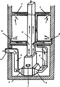
Figure 2. Scheme of air heating of a house: 1 - stove; 2 - filters; 3 - air intake pipe from the premises; 4 — fresh air intake; 5 — fresh air supply pipe; 6 — supply of warm air to the premises; 7 - air intake from premises; 8 - chimney.
After quickly warming up the premises, the automation switches on, allowing you to maintain the temperature at a given level. The advantages of air heating systems include:
- uniform heating of the room throughout the entire volume with a slight “pressure” of air, which completely eliminates drafts and the possibility of penetration of street dust;
- the ability to ventilate rooms, filter heated air to eliminate odors, germs and other foreign matter;
- low operating costs, allowing to increase efficiency up to 93%;
- ability to work in economical mode.
Gas or liquid heaters with safety automatics are used as heat generators. If the house is well thermally insulated, the heater is turned on 3-4 times a day to maintain the set temperature, which saves fuel and, consequently, money for heating residential premises. For example, to heat a small country house, one cylinder of liquefied gas is enough for about 8 - 12 days.
In almost all heating systems, the heat generated by the heat generator is transferred to the consumer by air. Even in a water heating system, water acts only as an intermediate coolant, and the final distribution of heat from the radiators still remains with the air. The only exceptions are heating devices from which heat is transferred by radiation - open fireplaces, infrared emitters, etc. But they play a limited role in heating residential buildings in our country.
The air is heated on heat-releasing surfaces (the surfaces of water heating radiators, convective-type electric heaters, “mirrors” of stoves, etc.) and enters the heated room, where it cools, giving off heat to walls, ceilings, and pieces of furniture. After this, the air should heat up again. This air circulation can occur under the influence of natural forces (warm air is lighter and therefore rises) or forcefully - due to a fan. In the future, we will use the term convection heating (by the way, here is general information about heating) for systems with natural air circulation and air heating (AH) for systems with forced air circulation.
This definition of VO is not generally accepted. A heating system is often called air-based if there is a system of air ducts for distributing heated air from a heat generator (without a fan). Wood-burning stoves such as “Buleryan” and “Professor Butakov” also fall under this definition, since they have the ability to connect air ducts and distribute warm air to other rooms due to convection.
Based on our definitions, these ovens should be classified as convection-type systems.
VO systems can be divided into two types - channel and local. Ducted systems require a system of air ducts, both supply and return. For local systems, air ducts are usually not needed. The simplest local heating systems are fan heaters and heat guns.
Figure 3. Direct heating heat exchanger: 1-hot air; 2- heat exchanger; 3-fan; 4-cold air; 5-burner; 6-chimney.
Figure 4. Indirect heating heat exchanger: 1 - hot air; 2 - heat exchanger; 3 - fan; 4 - cold air; 5 - burner; 6 - intermediate coolant circuit; 7-chimney.
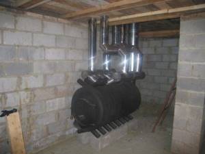
How to organize stove heating
An important advantage of any stove: it simultaneously heats the air and surrounding surfaces with intense infrared radiation. No batteries or coolant pipes are needed.
Clarification. Stoves or fireplace inserts with a water circuit can be used to heat 2-3 small rooms. The coil is connected to a gravity or closed system with a pump.
How to use a stove for pure air heating:
- For 1 room it is enough to install a cast iron or steel potbelly stove.
- To heat 2–3 rooms with a total area of up to 40 m², place a brick stove of a suitable design in the wall between the rooms.
- It is not easy to build a stove in a lived-in house. If there are no high aesthetic requirements, we install a potbelly stove, attach convection casings to the firebox and connect air ducts.
Cast iron stove with air pipes and a ceramic heat accumulator on the chimney
Option No. 3 involves laying air ducts into adjacent rooms and installing duct fans that can withstand the temperature of the moving medium 100–150 °C. Air can move through the pipes on its own, but too slowly, and the ventilation duct must slope upward. How such an air heating system works, see the video below.
The first two options are well known, but not always applicable:
- It is generally unrealistic to install a stove in an apartment;
- even a large Russian stove is not able to cover an area of more than 50 square meters (on one floor), so it is suitable for heating a dacha or a small house;
- the foundation plus a brick stove-fireplace is erected during the construction or major renovation of the building;
- a metal potbelly stove takes up space and is dangerous for small children (in terms of burns).
You can install an iron stove with your own hands - this is a tangible plus. But you will also have to heat it, which results in a lot of inconveniences: frequent loading, the smell of firewood and smoke in living rooms, dust. The author of the video acted wisely by placing the potbelly stove in a separate furnace room. We do not recommend repeating one thing after the home craftsman - installing air ducts made of aluminum corrugations. Such pipes create high aerodynamic resistance and greatly slow down the flow. It is better to use galvanized boxes.
We recommend: Insulation for walls inside a country house: price, material characteristics
Preliminary conclusion. Solid fuel stoves are a budget option for air heating with their own advantages and disadvantages. Suitable for small buildings - country houses, garages, greenhouses.
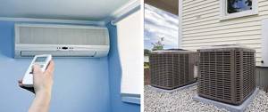
Application of air conditioners and heat pumps
As you know, modern split systems are able to operate in heating mode, consuming three times less electricity than a conventional electric boiler of the same power. Hence, a completely workable solution is to buy and install an inverter air conditioner in each room.
Reference. Why an inverter? The compressor in such “splits” does not stop, and therefore does not freeze in the cold. The air conditioner successfully heats the air down to -5 °C outside, after which the efficiency noticeably decreases.
The advantages of this scheme are obvious:
- lack of batteries, pipes, boilers and other heating equipment;
- relative ease of installation;
- aesthetic appearance of the indoor unit;
- cooling mode in summer;
- Possibility of installation in apartments.
The air-conditioned heating method is viable in the southern regions, where the temperature rarely drops below -15 °C. To the north, “splits” are used only during the transition period – in spring and autumn.
Other disadvantages of heating with a split system:
- Air conditioners will have to be installed in all rooms, which is unacceptable for cottages of 2–3 floors. A multi-split VRF system will cost more than the same number of single coolers/heaters.
- The device “can” clean, dry and change the temperature of the air flow. Rare models are designed to mix in outside air. This means that you will have to do separate ventilation.
- When the external unit of the air conditioner is operating, the distinct noise of the fan and the hum of the compressor can be heard from behind the wall.
The problem of efficiency at low temperatures is solved by an “air vent” heat pump, whose performance remains intact down to -30 degrees below zero. The design and operating principle are identical to the split system, the differences being the larger size and price. If the external unit is installed on the ground and carried 2-3 m from the building, the noise of the unit will become inaudible.
Brief conclusion. VRF systems are good for apartments and small houses located in the southern regions. Heat pumps can also be installed in northern latitudes, but the cost of the equipment plays a role here. If desired, you can install the air conditioner yourself.
Combined multi-zone systems
In this case, the coolant is still used, which is why the system is called combined. How this equipment works:
- Each room has an air heating/cooling unit - a four-pipe fan coil unit that looks like an indoor air conditioner unit.
- One pair of pipes supplies the units with coolant from the boiler. Hot water passes through a heat exchanger blown by a fan, causing the room air to heat up.
- When it is necessary to switch to cooling, the automation switches the fan coil to the second pair of pipes supplying cold water from the chiller.
- Users in rooms can set different air temperatures, but they cannot turn on cooling and heating at the same time. Hence the second name of the air conditioning system – multi-zone.
Note. Chiller is a type of refrigeration machine designed to cool liquid. Usually located on the street under a canopy or in an open place (depending on the design).
Various fan coil units are used inside the building - wall-mounted, duct-mounted, floor-mounted, ceiling-mounted. It all depends on the wishes of the homeowner and aesthetic requirements. Duct-type units can be built inside ventilation ducts to heat/cool the supply air.
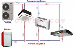
Connection diagram of a cassette, duct and floor fan coil to a chiller and boiler
Advantages of multi-zone air systems:
- applicable in large buildings with 20 or more rooms - administrative and residential buildings, warehouses, and so on;
- can work in conjunction with forced ventilation of the cottage;
- any heat generator is used for air heating - a boiler using solid fuel, gas, electricity, diesel fuel;
- pipes with coolant (coolant) take up little space, air units are easily built into the ceiling, hung on the wall or hidden behind the cladding;
- closed terraces with stained-glass windows covering the entire wall are heated by in-floor convectors or wall-mounted fan coil units;
- possibility of adjusting the temperature in individual rooms, remote control.
We believe that the boiler + fan coil + chiller scheme is the most universal and successful from the point of view of aesthetics and operation. Of course, you can’t do this type of air heating yourself; this is a minus. It is necessary to make calculations, select equipment, install, adjust... without knowing the basics, it is extremely difficult to carry out these works.
Let's list other negative points:
- high price of air conditioning units;
- the boiler and chiller are quite large devices, occupying 2–3 m² of area;
- the operation of the system depends entirely on electricity; when the lights are turned off, the heat supply will stop.
Conclusion. A multi-zone combined scheme is the best way to air-heat a home. But implementation will require significant investments.
Heating combined with ventilation
This is a classic method of heating buildings with air, used in enterprises since the last century. Subsequently, manufacturers began to produce small-sized analogues of industrial ventilation units installed in private homes. Thanks to less stringent requirements for air purity, the treatment scheme has also been simplified.
Let us explain the principle of operation of the “ventilation + heating” system step by step:
- The heat source is a stove, usually a gas one. A burner, an air heat exchanger, a fan and an electronic control unit are installed inside.
- The first network of ducts radiates from the furnace, distributing heated air throughout the rooms. With the help of diffusers, grilles and other supply devices, jets are supplied to the premises (usually to the upper zone).
- The second network of channels collects polluted/cooled air from the lower zone of the rooms into a common collector connected to the stove from below.
- Having passed through the collector, the exhaust air masses are cleaned in a mesh or cell filter, then sent to a heat exchanger, where they are heated by a burner.
- Electronics monitor the safe operation of the gas air heater, maintain the outlet temperature, and signal when the filters are dirty.
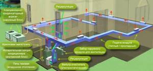
Typical air heating circuit with recirculation. The heater is a furnace and an air conditioner with a ducted indoor unit
Addition. Since the heater dries the air, an automatic humidifier with an electronic hygrometer is usually installed on the supply duct. The latter is located on the return air duct to measure the humidity of the flow.
The air heating stove is a rather noisy unit, so it is installed in a separate room. Combustion products are removed through a conventional or coaxial chimney (depending on the design of the heater). Air ducts made of galvanized steel are laid in several ways:
- in the basement or ground floor;
- hide in floors and wooden ceilings;
- in the attic;
- vertical channels run along the walls and are covered with facing materials.
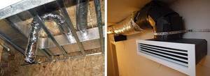
Large ventilation ducts are laid under plasterboard finishing
The supply air temperature reaches 40...45 °C, the speed of movement through the ventilation ducts is 4-5 m/s. You can't go any faster; there will be additional noise. In this situation, the diameter of the main collector reaches 300 mm, we took a typical flow rate of 1000 m³/h, although it can be more.
We recommend: 10 best steel heating radiators - 2020 rating and tips for choosing
A logical question: why heat air masses to 40 °C if 22 degrees is sufficient in the house? We answer: the heating system must compensate for 2 types of heat loss - through building structures and energy consumption for heating the inflow, since ventilation is needed in any case. Accordingly, we bring the air to a temperature of 20–24 °C (compensating for losses at home), then overheat it to 40…45 °C.
Conclusion. The “ventilation + heating” scheme is the most cumbersome and expensive. The building must be prepared in advance - even at the design stage, otherwise the air ducts will go directly through the rooms. Operating efficiency is highly dependent on the way the building is ventilated, which we will discuss next.
Pump disassembly
First of all, it is necessary to remove coupling 3 from the shaft of electric motor 2 (Fig. 10) and remove the pump 1 itself from plate 4. Then unscrew the bolts 34 (Fig. 11) and separate the right 4 and left 5 halves of the pump housing
The left half can be removed immediately; it will no longer be needed. After this, it is necessary to very carefully remove the impeller 1 from the shaft 23, unscrewing it by the blades and at the same time holding the coupling half located at the other end of the shaft 23 from turning. If you can’t unscrew it by hand, you can do it using a metal lever (crowbar). Place the lever between the blades of impeller 1 so that the edges of the lever protrude to the same length. You need to insert 2 metal rods into the coupling holes on the opposite side of the shaft and place the second lever between them, resting one of its edges on the ground.
Next, you need to carefully turn both levers counterclockwise.
There is no need to press too hard on the levers, as you can bend shaft 23. The unscrewed impeller 1 may also be needed if you want to make a more complex, but more efficient heat generator design. After this, you can unscrew the nuts 3 from the studs and disconnect the right half of the pump housing 4 from the bearing housing 2 (Fig. 11). The right half will also no longer be needed.
Let's move on to Figure 5. Here the cast-iron bearing housing is designated as position 1. The generator housing 2 is attached to it using studs 3, spring washers and nuts. Between them there is a gasket 6 made of paronite (fluoroplastic). Its thickness should be such that during assembly the emphasis falls on it, and not on the rubber lining of the rubberized surface of the housing 5. The shaft 4 is fitted with a steel ring 8, a rubber ring 9 and a pressure bushing 10. In place of the impeller there is a rotor 7. The length of the bushing 10 should be such that when the rotor is screwed onto the shaft, the sealing ring 9 is compressed and does not allow liquid to leak out during operation of the unit. The optimal length of the sleeve 10 is considered to be such that, after screwing the rotor, a gap of 0.5 mm remains between the end of the rotor 7 and the end of the sleeve 10. The size of 37 mm is indicated by an asterisk and indicates the length of the protrusion of shaft 4 beyond the body 1. The size of 22 mm indicates the length of the thread at the end of shaft 4.
Homemade heat generators
Nevertheless, as a demonstration of an interesting physical process, a home-made heat generator has the right to life.
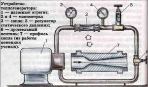
The easiest to manufacture is the “vortex tube”, or static heat generator.
Structurally, our Laval nozzle will look like a metal pipe with pipe threads at the ends, allowing it to be connected to a pipeline using threaded couplings. To make the pipe you will need a lathe.
- The shape of the nozzle itself, or more precisely, its output part, may differ in design. Option “a” is the easiest to manufacture, and its characteristics can be varied by changing the angle of the outlet cone within 12-30 degrees. However, this type of nozzle provides minimal resistance to fluid flow, and, consequently, the least cavitation in the flow.
- Option “b” is more difficult to manufacture, but due to the maximum pressure drop at the nozzle outlet it will also create the greatest flow turbulence. The conditions for the occurrence of cavitation in this case are optimal.
- Option “c” is a compromise in terms of manufacturing complexity and efficiency, so it’s worth choosing it.
Having made the nozzle, we can assemble an experimental circuit consisting of an electric pump, connecting pipes, the nozzle itself and a thermometer, which we use to determine the effectiveness of the device. To reduce the impact of heat dissipation into the environment, it is best to make the pipes short and wrap them with thermal insulation material. Having filled the circuit of the device with water and remembering its quantity, we turn on the pump for exactly an hour in order to determine the amount of electricity consumed using the electric meter.
The thermal power of a homemade heat generator can be determined using the following formula, known from a school physics course:
E=cm(T2-T1)
Where c is the specific heat capacity of water (4200 J/(kg*K)), m is its mass, T2 is the temperature of the water at the end of pump operation, T1 is the temperature at the beginning. The energy received, measured in joules. You can compare it with consumed electricity, taking into account the ratio of 1000 J per 0.000277 kilowatt-hours of energy. In other words, with 100% efficiency, a device that consumes 1 kilowatt-hour of energy will not be able to create thermal energy of more than 3600 kilojoules.
EXAMPLE: Our device heated 1 liter of water from 10 to 60 degrees in an hour. We get thermal energy of 210 kilojoules.
See what manufacturers say about such devices
Water heating in a wooden house
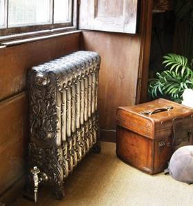
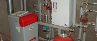
If we talk about the best heating for wooden houses with an area of 100 m2 or more, then a gas water system has been and remains the best option for such Objects.
Heating based on a water system is possible using various types of fuel. These are liquefied or natural gas, electricity, solid fuel, liquid fuel and alternative energy sources.
In addition, in addition to heating, the use of gas boiler equipment makes it easy to organize a hot water supply system.
The main advantages of water heating systems are low operating costs, as well as the ability to efficiently heat a turnkey wooden house of any size and configuration.
The disadvantages include the high cost of such systems, the complexity of installation, and the need for maintenance by qualified specialists.

Contact us and get advice from a qualified engineer!
We will help you understand the nuances and develop the optimal heating system!
To get a consultation
When installing heating with a liquid coolant on buildings built of wood, there are several important nuances, the consideration of which is necessary to obtain a high final result.
Varieties
Cavitation devices are divided into the following types:
- rotary - a vortex cavitation heat generator includes a modified centrifugal pump, the body of which is a stator with an inlet and outlet pipe. The main working part of the device is a chamber with a movable rotor that rotates like a wheel;
- static - the device has no rotating parts; for cavitation, a design of nozzles with a powerful centrifugal pump is used;
- tubular - the design includes longitudinally arranged tubes. The efficiency of tubular cavitation heat generators is high;
- ultrasonic – the cavitation effect is achieved using ultrasonic waves.
The efficiency of ultrasonic equipment is incredibly high.
Operating principle of rotary generators
Perhaps the most productive models include the Griggs design, in which a disk-shaped rotor has a surface with numerous blind holes of a certain diameter and depth. The stator is presented in the form of a cylinder with sealed ends in which the rotor rotates. There is a gap of about 1.5 mm between the rotor disk and the stator walls. In the cells of the device, turbulence is generated to form cavitation cavities. The number of cells is determined by the rotor speed.
As experts note, for the efficiency of the device, a rotor with a transverse size of 30 cm and a rotation speed of 3,000 rpm is used. With a smaller diameter, it is necessary to increase the speed parameters.
Features of rotary heat generators of cavitation action:
- there is a significant noise level;
- The efficiency of the device is not impressive;
- short service life;
- performance indicators are 25% higher than static models.
When operating a rotary unit, it is necessary to work out the precise operation of all elements, including balancing the cylinder. It is also necessary to promptly replace insulating materials for the shaft seal that have exhausted their potential.
Operating principle of a static heat generator
Cavitation involves a high speed of movement of the working fluid using a powerful centrifugal motor. Since d of the nozzle exit is significantly less than the parameters of the opposite end, the speed of movement of the substance increases, and cavitation effects occur.
Static cavitation devices have many advantages:
- no balancing or precise fitting of parts is required;
- the seals wear out less than in the rotary model, since there are no moving parts;
- The service life of the static cavitator is about 5 years, which is significantly longer than that of the previous version of the device.
If necessary, the nozzle is replaced, which requires a relatively small expenditure of time and effort, whereas in the case of a rotary device it will be necessary to recreate it again if the equipment fails.
Tubular heat generators: design and principle of operation
In this model, cavitation heat is generated due to the longitudinal arrangement of the tubes:
- the pump helps to build up pressure into the incoming chamber, and the working substance is directed through the tubes. In this case, bubbles form at the inlet;
- When entering the second chamber, where high pressure is established, the bubbles are destroyed, creating a thermal potential in the process.
The energy generated in this way is sent along with the steam to heat the house. According to manufacturers of tubular cavitation heat generators, as well as experts in the field of climate control equipment, this model is characterized by high efficiency indicators.
Features of ultrasonic cavitation generators
The installation creates ultrasonic waves, which generate cavitation heat. For this purpose, a quartz plate is used; on its basis, sound vibrations are created under the influence of electric current. They are directed to the entrance, subsequently creating vibration. During the reverse phase of sound waves, areas of rarefaction appear and the effect of cavitation is observed. The operating principle of the ultrasonic cavitator assumes minimal energy losses and virtually no friction. All this determines the exceptionally high efficiency of ultrasonic equipment.
Advantages and disadvantages
Like any other device, a cavitation-type heat generator has its positive and negative sides.
Among the advantages are the following indicators:
- availability;
- huge savings;
- does not overheat;
- Efficiency tends to 100% (it is extremely difficult for other types of generators to achieve such indicators);
- availability of equipment, which allows you to assemble the device no worse than the factory one.
The weaknesses of the Potapov generator are:
- volumetric dimensions, occupying a large area of the living area;
- high level of engine noise, which makes it extremely difficult to sleep and rest.
The generator used in industry differs from the home version only in dimensions. However, sometimes the power of a home unit is so high that there is no point in installing it in a one-room apartment, otherwise the minimum temperature when the cavitator is operating will be at least 35°C.
The video shows an interesting version of a solid fuel vortex heat generator
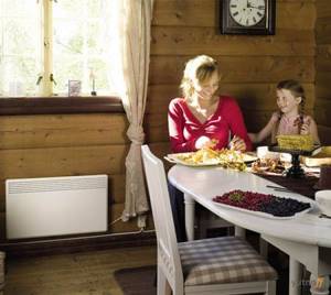
Heating a wooden house with electricity
The best heating option for a small (up to 100 m2) wooden house is to install electric convectors in it.
The main undeniable advantages of this option are:
- Low system cost
- Ease of use and maintenance
- High efficiency provided that the convectors are optimally positioned
- No need for fuel reserves
But along with this, it is necessary to be prepared for such shortcomings of the system in question as:
- High operating costs, which are associated with high electricity prices. Partly, the use of electricity meters operating on a multi-tariff principle can help reduce costs
- Electric heating in a wooden house depends on the availability and quality of the power supply. This entails additional costs associated with organizing a backup option in case of a network failure - an autonomous power supply (installation of a diesel or gasoline generator)
In addition, if you are thinking about organizing heating using electric convectors, then you need to know what electrical power is allocated to you. Often the allocated electrical power is not enough to heat the entire cottage.
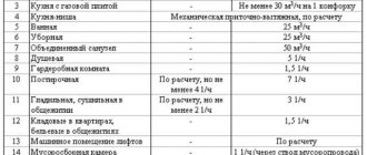
Carrying out heating design will answer the question of exactly how much electrical power is needed. But to a first approximation, it can be determined independently, using the pattern given in the table:
| Electric power | Thermal power | Area of heated premises |
| 1 kW | 1 kW | 10 square meters |
It is necessary to understand that the above pattern is an average. It works if we are talking about a cottage with standard insulation, standard windows and a ceiling height of heated rooms of ~ 2.5 meters.
If a wooden house differs from the standard, then work on organizing its heating must begin with a thermal engineering calculation.
Based on its result, it will be possible to accurately determine the thermal and electrical power required for full heating.
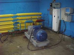
How to assemble a heat generator
With all these scientific terms, which can scare a person unfamiliar with physics, it is quite possible to make a VTG at home. Of course, you will have to tinker, but if everything is done correctly and efficiently, you can enjoy the warmth at any time.
And you have to start, as in any other business, by preparing materials and tools. You will need:
- Welding machine.
- Sander.
- Electric drill.
- Set of wrenches.
- Set of drills.
- Metal corner.
- Bolts and nuts.
- Thick metal pipe.
- Two threaded pipes.
- Connecting couplings.
- Electric motor.
- Centrifugal pump.
- Jet.
Now you can start working directly.
Installing the engine
An electric motor, selected in accordance with the available voltage, is installed on a frame, welded or assembled with bolts, from a corner. The overall size of the frame is calculated in such a way that it can accommodate not only the engine, but also the pump. It is better to paint the frame to avoid rust. Mark the holes, drill and install the electric motor.
Connecting the pump
The pump should be selected according to two criteria. Firstly, it must be centrifugal. Secondly, the engine power must be enough to spin it up. After the pump is installed on the frame, the action algorithm is as follows:
- In a thick pipe with a diameter of 100 mm and a length of 600 mm, an external groove of 25 mm and half the thickness must be made on both sides. Cut the thread.
- On two pieces of the same pipe, each 50 mm long, cut the internal thread to half the length.
- On the side opposite to the thread, weld metal caps of sufficient thickness.
- Make holes in the center of the lids. One is the size of the nozzle, the second is the size of the pipe. It is necessary to chamfer the inside of the hole for the nozzle using a large-diameter drill so that it looks like a nozzle.
- The nozzle pipe is connected to the pump. To the hole from which water is supplied under pressure.
- The heating system input is connected to the second pipe.
- The outlet from the heating system is connected to the pump input.
The cycle is complete. Water will be supplied under pressure to the nozzle and, due to the vortex formed there and the resulting cavitation effect, will begin to heat up. The temperature can be adjusted by installing a ball valve behind the pipe through which water flows back into the heating system.
By closing it slightly, you can increase the temperature and vice versa, by opening it, you can lower it.
Let's improve the heat generator
This may sound strange, but this rather complex design can be improved, further increasing its performance, which will be a definite plus for heating a large private house. This improvement is based on the fact that the pump itself tends to lose heat. This means that you need to make it spend as little as possible.
This can be achieved in two ways. Insulate the pump using any thermal insulation materials suitable for this purpose. Or surround it with a water jacket. The first option is clear and accessible without any explanation. But we should dwell on the second one in more detail.
To build a water jacket for the pump, you will have to place it in a specially designed hermetically sealed container that can withstand the pressure of the entire system. Water will be supplied exactly to this container, and the pump will take it from there. The external water will also heat up, which will allow the pump to work much more efficiently.
Vortex absorber
But it turns out that’s not all. Having thoroughly studied and understood the operating principle of a vortex heat generator, you can equip it with a vortex damper. A stream of water supplied under high pressure hits the opposite wall and swirls. But there can be several of these vortices. One has only to install a structure inside the device that resembles the shank of an aircraft bomb. This is done as follows:
- From a pipe of slightly smaller diameter than the generator itself, you need to cut two rings 4-6 cm wide.
- Weld six metal plates inside the rings, selected in such a way that the entire structure is as long as a quarter of the length of the body of the generator itself.
- When assembling the device, secure this structure inside opposite the nozzle.
There is and cannot be a limit to perfection, and the vortex heat generator is still being improved in our time. Not everyone can do this. But it is quite possible to assemble the device according to the diagram given above.
Do-it-yourself air heating of a private house
Making your own air heating is quite affordable. If this is done at the construction stage, and not in the finished building, then the goal becomes even more achievable. To understand how to make air heating in a private home, you first need to determine the desired result, and then technically calculate the possibility of achieving it. Calculations are the primary stage of this process. The algorithm of actions for independent organization of air heating may be as follows.
First you need to perform calculations:
- amount of warm air;
- heat loss;
- power of the necessary equipment.
It is better to carry out these calculations (if there is no knowledge and personal experience) with the participation of a practitioner.
Based on the project calculations, a plan for the air heating system is created. Note! If you have good modern thermal insulation, you can take into account the following practice-tested indicators when making calculations: 750–800 W of heat is required per 10 m² of room area.
Then, based on the project calculations, an air heating scheme is created. It should reflect the location of the system elements, the power of the main unit, the diameter of the air ducts, etc. You can use the diagrams offered on the Internet, but only if the technical conditions are suitable
Changes to completed drawings must be made with great care
After this, equipment is purchased
At this stage, it is necessary to pay attention to the certification of the equipment and the content of the instructions. In addition to the main units, you should purchase air ducts (preferably flexible, noise-absorbing)
To prevent the accumulation of condensate, the supply outlet should be insulated. For these purposes, it is recommended to use foil insulation up to 5 mm thick. It is convenient to use tape to connect air ducts. A good option is reinforced aluminum. Clamps made of metal or heat-resistant plastic are also suitable.
Next, the actual installation of the system is carried out. It must be carried out before finishing work
If the heating is installed in a finished room, it is worth paying special attention to the aesthetics of the boxes covering the air ducts
System Design Principles
When designing air heating systems, many important factors are taken into account. First of all, this is the heat demand of each individual room, as well as the heat loss for each room. Doors, windows, vents and other objects allow precious kilojoules of heat energy to escape.
The Buleryan stove is an economical heater option that can be used to organize air heating. A long-burning wood stove can also be an excellent solution.
The most important point is the presence of high-quality insulation of the building. If the house has plastic windows, good doors, and its facade is reliably insulated, there will be less heat loss, and heating costs can be significantly reduced. If we are talking about the reconstruction of a building, we should start with the design of insulation.
After the need for thermal energy and its costs are correlated, the power of the heating equipment is calculated and its type is selected. Then the hot air flow parameters are calculated. Special aerodynamic calculations are performed to calculate the required dimensions of the air ducts.
A diffuser grille is installed at the outlet of the air duct. Its size and configuration may affect the speed of air flow
You can preliminarily calculate the power of the equipment based on the following figures: for heating every 10 sq. meters of room you will need about 0.7-0.8 kW of heat. This is provided that the house is well insulated, otherwise more powerful equipment will be needed. But it is better to entrust complete design and detailed calculations to an experienced engineer.
Incorrect calculations can have a very bad effect on the state of the finished system. An unprofessionally designed air heating system is characterized by such problems as frequent equipment breakdowns, overheating of indoor air, overheating of equipment, drafts, and increased noise levels.
Simultaneously with designing an air heating system, it makes sense to think about the placement of stationary pieces of furniture in the house. Supply and exhaust grilles should be located in places away from the constant presence of people.
They also should not be hidden under cabinets, cabinets or other objects that impede the free movement of air masses.
In a multi-storey private house, it is recommended to place exhaust grilles in such a way that on the upper floors the cooled air is taken into the system from above, and on the lower floors - from below. This will ensure a more even distribution of heat throughout all rooms. Read more about how to correctly calculate air heating in this material.
Image gallery
Photo from
Inclined airflow direction
Scheme of operation of inclined warm air supply
Horizontal direction of heat supply
Vertical supply of warm air flow
Pros and cons of cavitation energy sources
Cavitation heaters are simple devices that convert the mechanical energy of a working fluid into thermal energy. Essentially, this device consists of a centrifugal pump (for bathrooms, wells, water supply systems for private houses), which has a low efficiency rate. Energy conversion in a cavitation heater is widely used in industrial plants where heating elements can be damaged if they come into contact with a working fluid that has a serious temperature difference.
Design of cavitation heat generator
Pros of the device:
- Efficiency;
- Economical heat supply;
- Availability;
- You can assemble a home thermal energy production device with your own hands. As practice shows, a homemade device is not inferior in quality to a purchased one.
Disadvantages of the generator:
- Noisiness;
- It is difficult to obtain materials for production;
- The power is too large for a small room of up to 60-80 square meters, it is easier to buy a household generator;
- Even mini-devices take up a lot of space (on average, at least one and a half meters of room).
Principle of operation
"Cavitation" refers to the formation of bubbles in a liquid, such that the impeller operates in a mixed phase (liquid and gas bubble period) of the environment. Pumps, as a rule, are not designed for mixed phase flow (their operation destroys bubbles, causing the cavitation generator to lose efficiency). These thermal devices are designed to induce mixed phase flow as part of fluid mixing, resulting in thermal conversion.
Heat generator drawing
In commercial cavitation heaters, mechanical energy drives the input energy heater (eg, motor, control unit), causing the fluid that produces the output energy to return to the source. This storage converts mechanical energy into thermal energy with little loss (typically less than 1 percent), so conversion errors are taken into account when converting.
A supercavitation jet energy generator works a little differently. Such a heater is used in high-power enterprises, when the thermal energy output is transferred to a liquid in a certain device, its power significantly exceeds the amount of mechanical energy required to operate the heater. These devices are more energy efficient than return mechanisms, in particular because they do not require regular checking and adjustment.
There are different types of such generators. The most common type is the rotary hydrodynamic Griggs mechanism. Its operating principle is based on the operation of a centrifugal pump. It consists of pipes, a stator, a housing and a working chamber. At the moment, there are many upgrades, the simplest is a rotary drive or disk (spherical) water pump. It is a disk surface in which many different blind-type holes are drilled (without exit), these structural elements are called Griggs cells. Their dimensional parameters and number directly depend on the rotor power, the design of the heat generator and the drive speed.
Hydrodynamic Griggs mechanism
There is a certain gap between the rotor and stator, which is necessary for heating the water. This process is carried out by rapid movement of liquid along the surface of the disk, which increases the temperature. On average, the rotor moves at approximately 3,000 rpm, which is enough to raise the temperature to 90 degrees.
The second type of cavitation generator is usually called static. Unlike a rotary one, it does not have any rotating parts; in order for cavitation to occur, it needs nozzles. In particular, these are parts of the famous Laval, which are connected to the working chamber.
To operate, a conventional pump is connected, as in a rotary generator, it pumps up pressure in the working chamber, which ensures a higher speed of water movement, and, accordingly, an increase in its temperature. The fluid velocity at the nozzle exit is ensured by the difference in the diameters of the forward and outlet pipes. Its disadvantage is that the efficiency is significantly lower than in a rotary one, especially since it is larger and heavier.
Current types of air heating systems
Today, experts offer several system options, each of which has its own characteristics, advantages and disadvantages. All designs differ in air circulation, area where air ducts are placed, and method of heat exchange.
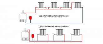
Natural circulation systems
The scheme is based on the physical property of warm air to rise to the top, for which air ducts and holes in the ceiling are installed to allow the flow to escape outside. The main advantage is low cost, but there are more disadvantages: low lifting speed, due to which heating of the room will be unnecessarily slow and the location of the air ducts in the upper part of the room - this may not always be convenient.
Forced circulation systems
The structures are complemented by a ventilation unit, the power of which depends on the number and total length of the air ducts. If you plan to heat a large room, several ventilation devices are selected. A special feature of the system is the forced supply of warm air into the premises. The method is characterized by rapid heating, therefore it is considered more practical for use in everyday life and in production.
Differences in duct placement
There are also two groups of designs:
- The floor arrangement involves air ducts that are installed in baseboards or mounted in the floor. This design is considered the most effective - warm air rises, the room warms up smoothly and quickly.
- Suspended arrangement is a scheme with air ducts built into ceilings or walls, with the outlets located in the upper part of the room (under the ceiling). The systems are considered less aesthetically pleasing, but there are ways to decorate pipes with ceiling plinths and other elements. Disadvantage: low temperatures near the floor, high temperatures near the ceiling. It is recommended to combine the systems with other heating options.
Types of systems by heat transfer method
Experts distinguish three types of structures:
Straight-through. The principle is simple: a heating device is installed in the lower part of the building to heat the air. The flows are then supplied to the rooms through air ducts. Holes are made in the ceiling to allow warm air to escape. Advantages - ease of installation and high-quality ventilation of rooms, disadvantage - high initial and operating costs, the air is literally used to “heat the street”. Direct-flow systems are needed for work in rooms where they work with hazardous substances, aggressive or foul-smelling substances.