Before you begin installing a heating system in a low-rise private house (one to two floors), you need to know that there are several options for its arrangement.
The main factors for choosing the most appropriate option are the available type of fuel and the cost included in the project. In addition, the design features of the building are taken into account: the presence of a basement and attic, the area of the premises, the materials from which the building and partitions are made, the presence of a separate room for the boiler.
When drawing up a competent project, which also takes into account the characteristics of the local climate and heat loss, the heating system will be effective and last a long time.
One of the most used heating schemes is a single-pipe heating system with bottom wiring. Its characteristic feature is that the main pipeline is laid in the basement or on the ground floor
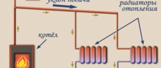
Diagram of a one-pipe and two-pipe heating system.
Sometimes it is possible to lay the pipe under the floor. In this case, the coolant goes from below the boiler to the heating devices (radiators). The mixture of gases resulting from fuel combustion is removed through a special air duct connected to a common riser. To prevent accidents, the supply and return risers are equipped with special shut-off valves.
A one-pipe heating system with bottom wiring is the opposite of a top-wiring scheme, in which a special expansion tank is mounted at the highest point of the heating pipe. The entire network branches out there.
Operating principle of water heating
The basis for the functioning of the heating system is the continuous circulation of the medium, which acts as a coolant. While moving through the pipes from the heating source (boiler) to the heating devices and back, thermal energy is released and the premises are heated. Not only water, but also air, steam or antifreeze (in houses of irregular residence) can be used as a coolant. However, water heating systems are most widespread.
When arranging traditional heating, physical phenomena and laws are used - thermal expansion of water, convection and gravity. After heating through the boiler, the coolant expands, causing pressure to build up in the pipeline. The medium loses its density and weight. The heavier and denser cold water below pushes the heated portions upward: this explains the exclusively vertical positioning of the supply pipe leaving the boiler.
Thanks to the created pressure and convection, the coolant circulates inside the batteries, gradually giving them its heat. This exchange of energy leads to heating of the premises. The water returning back is usually at a low temperature: after this, the cycle begins again.
Heating that operates due to natural circulation is also called gravity and gravity. Stable circulation of liquid is ensured by the inclination angle of the horizontal pipes of the system. Usually this is 2-3 mm per linear meter. As a result of heating the coolant, hydraulic pressure is created in the line. Since water can be compressed, even a slight excess of the norm is fraught with serious consequences. To prevent this, any heating circuit is equipped with a special compensating device - an expansion tank.
Design and principle of operation
Any water CO is based on heat exchange between the coolant (water, brine, antifreeze), which circulates along the circuit, and the air of the heated room. Depending on the architecture of the heated room, there are two options for supplying water to the radiators: through sun loungers (horizontal main pipeline) and vertical risers.
The principle of operation of a horizontal single-pipe heating system is as follows: the coolant circulates in the main pipe, forming a closed loop that begins and ends in the heat generator. It is to one main line that all the equipment necessary for CO operation is connected.
What is the difference between one-pipe and two-pipe schemes
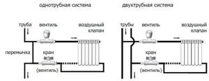
Water heating can be single-pipe or double-pipe. The main difference between them concerns the method of switching heat-emitting radiators and the supply line. The diagram of a single-pipe heating system has the form of a closed annular circuit. The starting point for laying the pipeline is the heating device. To connect radiators to it, a sequential method is used. After the last heater, the pipe returns back to the boiler. A system with one main line is characterized by simplicity of arrangement. In this case there are not many components, which allows you to significantly save on installation.
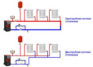
In a two-pipe scheme, two lines are used to move the coolant. Using one of them, the hot coolant is delivered from the heating device to the heat-releasing devices. The second pipe carries the cooled water back to the boiler. To switch heating radiators, a parallel method is used: hot liquid is supplied to each of them directly from the supply pipe. As a result, all radiators in the system have approximately the same temperature. Inside the radiator, the coolant releases its energy. After this, it is discharged into the return pipe in a cooled state.
The arrangement of a two-pipe circuit involves the use of twice the number of components (fittings, pipes and fittings). In this case, complex branched structures can be used without problems. Reduced heating costs are achieved through individual adjustment of batteries. Using a two-pipe system, large multi-story buildings can be efficiently heated. It is more practical to equip low-rise buildings no higher than two floors with an area of up to 150 m² with single-pipe systems. This is more profitable both from an aesthetic and economic point of view.
Types of heating systems
The heating circuit includes: a heat source, pipes for transporting coolant and heat-releasing devices. The working medium, heated by a heat source, moves through the pipeline, giving off heat to the premises of the house. Having gone all the way, the cooled coolant returns to the heating device, heats up again and the cycle repeats.
Water heating is usually used to heat residential buildings, since water is available and relatively safe. But the heating system can also work with another working medium: air or antifreeze. These coolants are usually used in homes where heating is turned on sporadically.
To heat residential buildings and functional buildings, one- and two-pipe heating systems are used.
- In a one-pipe system, heating batteries are connected in series to the heating main. The coolant passes through all the radiators in turn and the circuit closes at the heat source. The pipeline layout is simple - the supply and return of the working medium is carried out through one pipe. Installation does not require a large number of node connections, so the single-pipe system is popular for heating small buildings and private houses.
- In a two-pipe system, the batteries are connected to the pipeline in parallel between the supply pipe and the return pipe. The hot working medium enters the batteries from the supply pipe, and the cooled one is immediately discharged into the return pipe. Installation is more complicated because it is necessary to perform many branches and nodes, and the final cost of the heating network is higher.
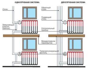
Note! Two-pipe heating circuits are effective for heating buildings with a large area or number of floors - all radiators receive a working environment of the same temperature, which allows all rooms to be heated approximately equally. In private buildings, such heating systems are rarely used.
What is single-pipe heating?
Any heating system consists of the following components:
- Heating device (boiler). Can be solid fuel, electric, gas, etc.
- Heat-dissipating devices. Batteries or underfloor heating system.
- A device for creating circulation inertia of the coolant. This could be an accelerating section of the main line or a water pump.
- Compensator for excess coolant pressure in the system. Expansion tank (open or closed).
- Pipes, fittings and necessary fittings.
The choice of heat supply scheme is directly dependent on the type of devices used.
Does a single-pipe forced circulation heating system save energy?
In the two-pipe heating option, heat energy is directly saved. When rooms overheat, thermostats reduce the flow of coolant through heating devices, and at the same time its flow through the risers decreases, i.e. the excess volume does not circulate through the pipes.
In a single-pipe heating system with thermostats, when the rooms overheat (when their valves close), the overall forced circulation of liquid does not decrease - it simply does not enter the batteries, and, accordingly, does not cool down in them. Heat energy is not saved here, but it is not wasted either, remaining in a stable volume of heated coolant. But its temperature in the “return” increases, which leads to an increase in losses in pipelines. However, in heating stations of apartment buildings, the DHW heat exchanger (if available) is powered from the return line, in which the water cools before returning to the boiler room.
Natural circulation
To ensure the movement of water in a gravity system, it will be necessary to construct an acceleration section. We are talking about a vertical pipe extending from the boiler, inside which the heated coolant moves upward. Upon reaching the highest point, the pipe smoothly turns back: this gives the water the necessary acceleration to move along the highway. Heating systems with overhead wiring do not require a separate pipe: its function is performed by a supply pipe raised to a sufficient height.
In one-story buildings with lower horizontal wiring, efficient heating will require an accelerating manifold. It should rise above the level of the first battery by no less than 1.5 m. Thanks to the acceleration section, circulation of the coolant in the gravity heating system becomes possible. The pipes in this section have a larger cross-section compared to the rest of the circuit. For example, if the diameter of the system pipes is 25-32 mm, then the acceleration section should have a diameter of 40 mm. The main advantages of the gravity system are its absolute energy independence (if a solid fuel boiler is used), simplicity of the device and the absence of complex components.
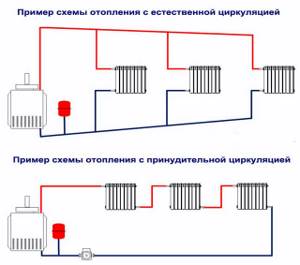
There are also disadvantages:
- To minimize hydraulic resistance, it is necessary to use large diameter pipes.
- The installation of any device and device leads to difficulty in the movement of the coolant, so there are certain restrictions on the number of shut-off valves (the fewer, the better). As a result, repair and maintenance becomes more complicated, since it requires a complete shutdown of the system and draining the coolant from the circuit.
- In order for the gravity system to be as reliable as possible, careful calculation and balancing will be required. This involves selecting optimal pipe diameters and the number of radiator sections. The batteries furthest from the boiler have to be made an order of magnitude wider: the coolant reaches them sufficiently cooled.
Installation recommendations
It is recommended to reduce the significance of the disadvantages of a single-pipe system by fulfilling the following conditions:
- To prevent the heat transfer of distant radiators from decreasing, the heat transfer area is increased - the further away from the boiler, the more sections there are.
- The required heat consumption in premises for various purposes is taken into account. Bedrooms and children's rooms should be the warmest, but there is no need for heat in the kitchen - there are already enough heat sources there. Therefore, it is rational to conduct the heating circuit in such a way that the radiators or heated floors in residential premises are the first on the path of the coolant, and the last are non-residential premises.
- If following the previous recommendation is impossible in the existing layout of the house, heating of the premises is regulated differently: the shortest radiator is installed in the kitchen, and the longest in living rooms. In non-residential premises where heat is not required, you can do without a heat-releasing device altogether by passing only one pipe through them.
- To ensure circulation, the pipeline is laid with a slight slope: at least 0.5 cm per meter in a pumpless system, from 0.3 cm per meter in the presence of a pump.
- The pump is usually installed on a section of the pipeline with a minimum coolant temperature - between the last heat-transfer device and the heat source. This allows you to extend its service life.
- The height of the accelerating manifold is 2.2 m, its top point must be at least 1.5 m higher than the connection to the first radiator.
- The expansion tank can be installed in the attic, insulating it.
- For ease of maintenance and increased service life, the membrane tank is installed in a section of the heating network with the lowest temperature of the working environment. However, if there is a rise in the system, the highest section of the pipeline is selected for installation.
Forced circulation
Neutralization of almost all of the listed disadvantages is achieved by introducing a circulation pump into the system. As a result, the coolant receives an additional impulse, thanks to which it effectively overcomes the hydraulic resistance of the pipeline. Single-pipe heating system wiring is currently the most popular solution in private homes.
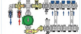
The installation location for the pump can be any section of the highway. However, it should be borne in mind that when rubber elements (gaskets) are exposed to hot water, the service life of the pump is noticeably reduced. Therefore, they try to install the device on the return pipe, because The coolant there is not so hot. A coarse filter must be installed in front of the pump to prevent various contaminants from entering the mechanism. When connecting all instruments and devices, it is recommended to use shut-off valves and bypasses. This will significantly simplify repair and maintenance activities at individual units: in this case, there is no need to stop the entire system and completely drain the coolant.
Strengths of forced circulation heating circuits:
- Possibility of using more complex branched circuits, leading to an increase in the total length of the circuits.
- There is no need to increase the diameter of the pipes. Thanks to the pump, sufficient pressure is created inside the system for movement and uniform distribution of liquid.
- The circulation has a stable speed. This indicator is not affected by the level of heating of the coolant and the installation of the accelerating manifold.
- There is no need to organize inclination angles on horizontal sections of the pipeline, because A pump is used to stimulate the movement of the coolant.
- It becomes possible to insert control devices on all batteries, which ensures the maintenance of an optimal heating level, reducing energy consumption and heating costs.
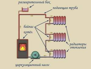
There are also disadvantages:
- The need for electrical power.
- Noise from a running pump.
- The need for additional capital investments (when compared with the gravity scheme).
Neutralizing them usually does not cause difficulties. To maintain a stable energy supply, an autonomous electric generator is being installed. Systems that provide the possibility of switching to a natural circulation mode have proven themselves very well. To reduce the noise from a running pump, it is usually installed in a non-residential area.
Single-pipe wiring diagrams
If a single-pipe heating system is organized in a private house, radiator heat exchangers can be connected to the circuit in the following ways:
Consistently. The sequential order of connecting batteries consists of lining them up in a chain, with the return pipeline of each being connected to the supply of the next one.
It is clear that the first radiator in the chain will heat up more than the subsequent ones, with a gradual decrease in the heat transfer of more distant ones; with a large number of batteries, the very last one risks remaining completely cold. In addition, if a malfunction occurs in one of the sections, it will be necessary to shut off the flow of coolant throughout the entire circuit, and blockages can lead to dangerous emergency situations.
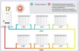
Rice. 5 Parallel connection of batteries in a single-pipe Leningrad and its features
Parallel. This single-pipe heating scheme is used much more often than the option discussed above. In it, the central pipe makes a loop from the boiler outlet to its inlet, and each radiator is connected to the pipeline with two bends. Heating in one pipe with radiators connected in parallel was called Leningradka and was previously widely used for heating government facilities and institutions, and public places. Leningradka has not lost its relevance even today; it is often used in cases where saving materials and ease of installation are of paramount importance.
Single-pipe distribution in gravity systems
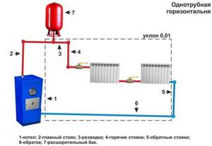
In gravity (gravity) systems, water heated by the boiler rises up into a storage tank and goes down through an inclined horizontal pipe. A number of radiators are connected in series to the pipeline; a return pipeline to the boiler departs from the outlet pipe of the latter.
Options for connecting batteries to the boiler can be different, but most often the lower Leningrad connection is used (Fig. 5), much less often the diagonal when connecting heat exchangers in series (Fig. 6).
Since the flow rate in all gravity systems is low, the heating fluid is transported through a pipeline with a diameter of at least 40 mm.
The diagonal sequential circuit does not allow adjusting the heating temperature of each heat exchanger by changing the volume of coolant passing through the radiator. It has all the disadvantages of connecting radiators in series, associated with the lowest heat transfer of the latter in the battery chain.
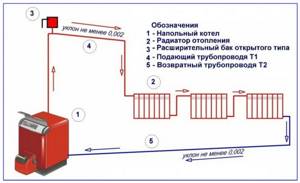
Rice. 6 Scheme of a single-pipe gravity heating system
Related article:
Selection of a circulation pump for a heating system - methods, calculations. It may be interesting to learn in more detail about the types of heating pumps, proper selection and installation. All this can be read in a separate article.
Closed single-pipe forced circulation heating system
In systems with forced circulation, the heating fluid is pushed through the pipeline by an electric pump. Thanks to this, it became possible to lay pipelines from the boiler in a horizontal position and connect radiators located on the upper floors to it.
When wiring with one pipe, a parallel battery connection circuit is used, called Leningradka. In this wiring, the heat exchangers are connected from below, but there is also a diagonal version of their connection with approximately the same efficiency.
When organizing a Leningrad line, it is recommended to lay the main line from large-diameter pipes of 32, 40 or 50 mm.
Radiator outlets are usually made from 20 or 25 mm pipes.
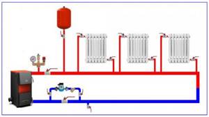
Rice. 7 Single-pipe forced circulation circuit
The circuit has the ability to change the heating temperature of each radiator in the circuit by installing control valves - valve taps, thermostats - at the input or output of the battery.
Sometimes temperature control is carried out using additional valves installed under each battery.
Another common option for leveling the heat transfer of each radiator is to increase the number of sections in the heat exchangers furthest from the boiler.
When using Leningradka in everyday life for heating individual residential buildings, owners should consider the following. Since most of the coolant passes through a closed pipeline loop without getting into the radiator heat exchangers, its energy efficiency is more than 2 times lower compared to a two-pipe distribution.
Leningradka is a loop connection scheme, that is, if the pipeline with batteries is not located along the entire perimeter of the room, the return line will have to be laid next to the supply line. As a result, two pipes will run along the wall, which in terms of aesthetics and material consumption is comparable to a two-pipe dead-end wiring.
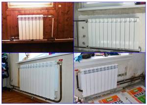
Rice. 8 Examples of diagonal battery connections
Single-pipe wiring in communal houses
Most communal houses use single-pipe heating. The coolant enters from below or above into the side pipes of the batteries and is also discharged from the side on the same side.
Open tank
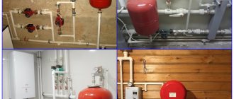
An open expansion tank is a partially or completely open tank connected to the circuit in its highest section, immediately after the boiler. To prevent the liquid from overflowing over the edges of the vessel, there is a special pipe closer to the top: it serves to drain excess water into the sewer or onto the street. When organizing heating of one-story buildings, a compensating tank is usually installed in the attic. To avoid freezing of water in winter, the walls of the tank are additionally insulated.
Such heating systems are called open. Most often we are talking about non-volatile or combined heating. In this case, the coolant comes into direct contact with the air: this leads to its natural evaporation and enrichment with oxygen.
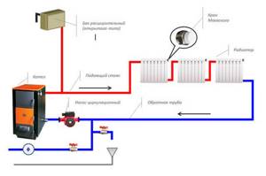
Open circuits have the following disadvantages:
- Accurate observance of slopes (if gravity systems are used). This will allow the air leaking into the pipes to escape through the container into the atmosphere.
- The need for constant monitoring of the water level in the tank. From time to time, the volume of coolant must be replenished, since part of it evaporates through the open top.
- The use of non-freezing liquids that emit toxic substances during evaporation is prohibited.
- Oxygen saturation of the circulating fluid provokes corrosion processes inside metal steel heating radiators.
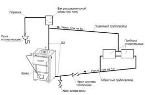
Strengths of open systems:
- You may not need to regularly check the pressure level in the pipeline.
- Small leaks in the circuit will not prevent it from properly heating your home. The main thing is that there is enough liquid in the pipes.
- To replenish coolant losses, it is allowed to use a simple bucket. This is done by simply adding water to the expansion tank to the required level.
How does a one-pipe system work?
The thermal circuit consists of functional elements:
- heat generator - a boiler that heats the coolant;
- a pump or accelerating manifold that ensures circulation of the working medium;
- a compensating device that regulates pressure in the pipeline;
- heat-releasing elements - radiators or heated floors;
- connecting all pipe elements.
We recommend that you read: Corrugated drainage pipe with perforation
Systems with natural and forced circulation
To transfer heat from the boiler to the heat-transmitting elements, constant circulation of the coolant is necessary.
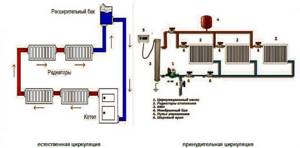
The installation of an accelerating manifold - a loop-shaped pipe vertically removed from the boiler - allows you to create natural circulation of the working environment.
From the boiler, the heated coolant tends to rise due to its high temperature. After passing the top point of the collector, under the influence of gravity, the coolant rushes down with free fall acceleration. Having rapidly picked up speed, the working medium continues to move further along the pipeline by inertia.
The constant movement of the working medium in the heating circuit can be ensured by equipping the system with an electric pump, which gives the coolant the necessary impulse.
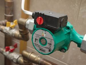
Heating circuits equipped with a circulation pump are called forced circulation systems.
| Circulation type | Advantages | Flaws |
| natural |
|
|
| forced |
|
|
Open and closed type compensating device
Due to the expansion of the working medium when heated, excess pressure is created in the pipeline; when the heating system is turned off, on the contrary, the pressure in the pipes decreases. These fluctuations negatively affect the elements of the heating network and can cause breakdowns.
To compensate for the coolant pressure, an expansion tank is included in the thermal circuit. Excess heated working medium enters the tank, the pressure in the pipes decreases, and when the heating is turned off, the tank returns the coolant to the circuit, compensating for the insufficient pressure.
Compensating devices are of open and closed type:
- An open type tank is a container that is fully or partially open. Such a device is installed in the upper part of the pipeline above the cat. The hot water entering the tank gradually evaporates, which can result in a lack of coolant in the heating circuit, so water needs to be added to the tank. In order not to monitor the water level, the tank is connected to the water supply and equipped with a valve with a float. To prevent boiling water from spilling over the edge when the container is overfilled, a spillway is installed in the tank, leading it to the sewer.
- A closed tank works on the same principle as an open one, but the coolant does not come into contact with the external air. The compensation device is a completely sealed container, divided inside by a membrane into two compartments. One of the compartments is connected to the pipeline, the second, which has an air valve, is filled with air. When the heating is turned on, the hot coolant fills the tank, presses on the membrane, compressing the air in the second compartment. As the working medium cools, the pressure decreases and the already compressed air presses on the membrane, returning the coolant from the tank back into the pipeline. At critical pressure in the second compartment, the air valve opens and excess air is gradually released - this allows you to equalize the pressure in the tank and avoid damage to the device.
We recommend that you read: Welded air ducts made of black steel
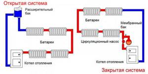
Note! If there is a rise in the system, the highest section of the pipeline is selected for installation.
| Type of compensation device | Advantages | Flaws |
| open |
|
|
| closed |
|
|
Methods for connecting radiators
Bottom, diagonal and side connections of radiators can be used:
- Lower: The pipe is connected to the lower radiator pipes. This connection allows you to place the pipes along the floor, making them minimally noticeable in the interior of the room, or to hide the pipes under the baseboard. However, the upper parts of the battery warm up poorly, and heating efficiency decreases.
- Diagonal: the coolant enters the upper pipe on one side of the radiator and leaves the lower pipe on the opposite side. The most effective connection - the battery warms up completely and transfers maximum heat to the room;
- Lateral: pipes are used on one side of the radiator. The connection is used to connect to the heating riser.
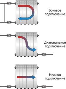
Closed tank
A closed expansion tank is a durable, sealed container separated inside by a flexible membrane. One part is inflated with air, and the second is connected to the pipeline. When the coolant heats up, its volume increases. As a result, the membrane bends towards the air section, which acts as a damper. Cooling the water leads to a decrease in hydraulic pressure. Thanks to compressed air, the system comes into equilibrium, squeezing excess water back into the main line.
Systems equipped with an expansion tank with a membrane are called closed. We are talking about sealed closed hydraulic circuits. The compensating tank can be installed on any part of the system. A popular installation location is the return pipe near the boiler: this increases the ease of maintenance of the tank.
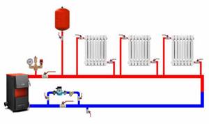
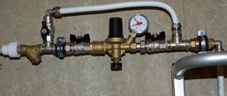
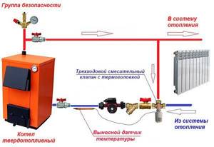
In closed heating systems there is usually a slight excess pressure, so they are necessarily equipped with a safety group. The unit includes an air vent, a pressure gauge and a safety valve for discharging the coolant in emergency mode. These devices are installed on the supply pipeline, which allows shutdowns for repairs and maintenance. On elevated pipelines, the safety group is usually located at the highest point.
Methods for connecting radiators
We have already said that in single-pipe heating systems the coolant passes through the radiators sequentially. Here it is customary to use radiators with lower inlets and outlets to ensure unhindered passage of coolant. This also helps maintain its temperature (by taking the shortest path, it does not cool down so quickly). The same applies to forced circulation, where care must also be taken to minimize heat losses along the coolant path.
Diagram of the lower connection of radiators in a single-pipe heating system.
The need to use lower inputs and outputs is also due to the fact that this reduces the number of bends and reduces the cost of installation. If you have about 10 radiators installed, and you want to use a diagonal connection, then the number of bends in the composition is more than 20 pieces - this will impede the passage of the coolant and reduce the temperature so much that the circulation pump simply does not have enough strength to compensate for its drop.
If you decide to install a single-pipe heating system, we recommend using radiators with a bottom supply - thanks to this, you will save on materials and fittings, and assemble a more efficient heating system.
We have already figured out that the coolant should enter the batteries from below and exit on the opposite lower side. But the efficiency of such a system will be low, even when using a circulation pump. What to do in this situation? It will be saved by using the Leningradka radiator connection diagram. Advantages of the scheme:
- More efficient heating of distant rooms;
- Minimum costs for installing bypasses;
- Ability to repair and replace batteries while the system is on;
- Possibility of adjusting the heating temperature in each room.
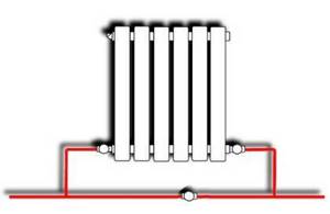
The so-called battery connection diagram is “Leningradka”. It is based on the use of bypass.
A bypass is a jumper that is created between the inputs and outputs of radiators installed in the system. One or three valves are installed here. One valve is placed on the bypass itself and allows you to turn it on and off. The second two valves are placed at the inlet and outlet. If you need to disconnect the battery from the system, close the input and output valves, open the bypass valve and remove the battery (for replacement or repair).
To adjust the degree of heating of the room, we can turn on or off the bypass, or completely exclude the battery installed in the room from the heating system (the coolant flows through the bypass). This is only possible using the Leningradka battery connection diagram.
You don’t need to try other methods of connecting radiators, as they will not provide adequate efficiency and will not allow for more uniform heating of the rooms.
Connecting the battery to the main pipeline
The level of heat transfer from radiators is affected by the way they are connected to the main line:
- Diagonal (cross) . This option demonstrates the greatest efficiency. Makes it possible to heat radiators as much as possible over the area, practically eliminating heat losses. In this case, the supply pipe is connected to the upper radiator pipe, and the return pipe is connected to the lower pipe (it is located on the opposite side of the device). Diagonal connection is mandatory for multi-section radiators.
- Lateral (one-sided) . Provides uniform heating of all sections of the battery. In this scheme, the supply and discharge pipelines are located in the same direction. The side connection is most popular when organizing heating with top wiring.
- Nizhny . Least efficient connection method. Despite this, it is often used when the main pipe is hidden under the floor. The inlet and outlet pipes are connected to the lower outlets on different sides of the battery.
Pros and cons of the system
Among the main advantages of single-pipe type heating are the following:
- Convenient and simpler camouflage of pipes in walls and niches.
- Quick installation.
- Optimal for organizing heating on several floors. In this case, only one line will need to be drawn through the floors.
- Closed systems are easily adjusted using a radiator valve.
- Laying a single pipeline is cheaper than installing double systems.

Such systems also have some disadvantages:
- Cooling of the coolant when moving to remote batteries. The cross-section of the pipeline and the number of sections have restrictions on expansion. For optimal system operation, the circuit may contain 4-5 batteries.
- For good coolant flow, it is necessary to install full-bore elements on the branches. An increase in the resistance of the fittings pushes the liquid in a straight line, reducing its consumption.
- Hydraulic instability, manifested in the effect of the condition of one radiator on others in the branch. For example, blocking the valve on the first device will lead to an increase in the temperature in subsequent battery blocks, which will begin to overheat the room.
- Higher costs than installing a shoulder system consisting of a pair of pipes.
- Difficulty in calculations and balancing. The size of the heat-transfer surface and the power of the devices should be determined extremely accurately.
- Large tube size.
Efficiency of a single pipe system
When developing a project for installing a single-pipe heating system, it is necessary to take into account many factors:
- Is there a constant power supply?
- Possibility of allocating a separate room (boiler room) for equipment.
- How many floors are there in the house?
- Design features and level of aesthetics of the future system.
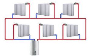
Each individual situation is characterized by its own specific arrangement of equipment and methods of its switching. It is most practical to equip small premises (for example, a country house) with a simple gravity circuit with sequential switching of radiators directly into the main pipe. Using 2-3 batteries, you can do without a significant amount of shut-off valves: in this case, you can simply drain the water from the system if necessary.
If the building has a large area, a complex heating system with a number of branches is required. In such a situation, the best option would be a forced heating scheme of the Leningradka type. It is characterized by the use of diagonal switching of heat-releasing devices and the presence of adjustable bypasses.
Types of structures
Heating systems can have natural or forced (artificial) coolant circulation
The first option is the classic type of pipeline formation with an expansion tank, which is mounted under the ceiling and receives heated water from a boiler or furnace. The liquid moves by gravity through the tubes to the batteries. This method is reliable and easy to install, and optimally performs its tasks in rooms with a small area.

Natural circulation

Forced (artificial) circulation
Modern devices are almost universally equipped with built-in pumping systems for circulation. They allow you to organize more complex and large-scale heating lines for large areas.
The pump is connected separately to solid fuel boilers. This is due to the strong heating of the equipment during fuel combustion.
Expert opinion
Grebnev Vadim Savelievich
Heating system installer
Some systems (for example, heated floors) can only be installed with artificial circulation; they will not function with a gravity circuit.
Heating circuits can also be closed or open:
- Older heating options often had an open design . As it warmed, the liquid level in the tank increased and decreased as it cooled. A special pipe served to discharge steam and excessive pressure into the street or into the sewer to prevent overheating of the line.
- Modern closed-type devices for this purpose are equipped with an expansion tank that compensates for the increase in pressure . For solid fuel units, a larger tank is provided, as well as a valve for removing steam and automatic water replenishment.
Strengths and weaknesses of single pipe systems
The popularity of single-pipe heating in private construction is explained by the fairly low cost of the structure and the ability to independently carry out installation work. This makes it possible to save on hiring specialists.
Among other advantages of single-pipe systems, the following should be highlighted:
- High level of hydraulic stability. If you turn off some of the circuits, this will not affect the heat transfer of the remaining elements of the system. The same applies to replacing batteries or increasing the number of their sections.
- Low pipe consumption for organizing a main line.
- Slight inertia. To heat up the system, an order of magnitude less coolant is required than in schemes with two pipes.
- External aesthetics. Installation of a single-pipe system usually does not affect the beauty of the interior of the room, especially when using hidden laying of the main pipe.
- Thanks to the use of innovative shut-off valves (automatic and manual thermostats), it is possible to fine-tune the operating modes of the heating circuit and its constituent devices.
- Simplicity and reliability of the design, which makes it possible to install a single-pipe heating system on your own. The same applies to heating maintenance during operation.
By organizing the connection of control and monitoring devices for the heating system, it is possible to achieve its functioning in automatic mode. Integration into the Smart Home system is also allowed: as a result, it becomes possible to program optimal heating modes, taking into account the time of day, season, etc.
The main disadvantage of a single-pipe heating scheme is the presence of an imbalance between the heating of the radiators, depending on their distance from the boiler. This is explained by the gradual cooling of the coolant as it circulates through the pipes. As a result, the batteries closest along the coolant path turn out to be hotter than those located further away. In such cases, it is better to use cast iron devices, which are characterized by slow cooling.
Advantages and disadvantages of a single-pipe heating network
The advantages of such a heating circuit are especially pronounced if the installation and maintenance of the heating network is done by yourself:
- ease of installation,
- low consumption of materials;
- low cost,
- quick warm-up of batteries.
There are practically no disadvantages to this simple system if it is used to heat a small house.
We recommend that you read: Which cleaning agent to choose to remove blockages in the sewer system
With the increase in the total area of the premises, the main disadvantage of the heating network becomes noticeable, and sometimes critical, - heat loss on each heat-emitting device - the further the battery is from the beginning of the circuit, the less it heats up.
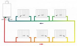
This leads to the second drawback - the complexity, and sometimes even impossibility, of using such a thermal circuit for heating buildings with a large total area.
Other ways to solve the problem
In addition to the use of cast iron batteries, the introduction of a circulation pump into the single-circuit system helps to optimize the situation. After this, the temperature in the heating circuits becomes more uniform, but too long pipelines still lead to its noticeable cooling.
To smooth out this unpleasant phenomenon, two methods are proposed:
- As you move away from the boiler, it is recommended to increase the number of sections on the radiators. In this way, an increase in their heat-releasing area is achieved: thermal energy begins to spread in greater quantities in the rooms, contributing to their uniform heating.
- Before carrying out single-pipe heating, it is necessary to consider the most rational placement of radiators in the rooms. It is better to place devices with the highest power in children's rooms, bedrooms and rooms on the cold north side. Further, the highway leads to the living room and kitchen. At the end of the circuit there are non-residential and utility rooms.
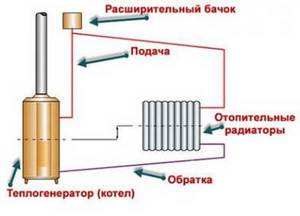
Thanks to these measures, some compensation for the shortcomings of the single-pipe system is achieved. This especially applies to low-rise buildings with an area of up to 150 m². In such cases, single-pipe heating is the most economical option.
With natural circulation
For natural circulation, the height difference between the highest and lowest points of the contour is important. In a single-pipe connection scheme, it will not be possible to separate the supply and return without a significant increase in cost, because more pipes will be required.
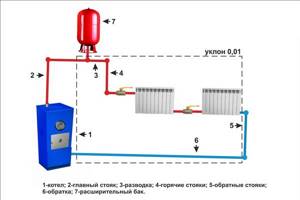
Scheme with natural coolant circulation
A simple solution and at the same time practical would be an accelerating manifold. From the boiler, the pipe first rises vertically upward to the expansion tank in the case of an open system. Next, the pipe is lowered down an inclined path to the first radiator.
Raising the accelerating manifold will give the hot coolant the required acceleration so that it can circulate around the circuit. Naturally, the pipes are selected in diameter as large as possible to reduce resistance.
The bypass sections between the inlets of each radiator are formed by a pipe just one size smaller. Control valves should not be installed on the bypass so as not to interfere with the coolant flow.
It is difficult to regulate the efficiency of each heat exchanger in such a scheme; the accuracy of the adjustment will be very mediocre. Thermostats directly at the connection of the radiators themselves will significantly reduce heat transfer.
