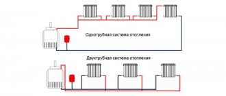
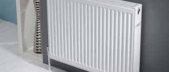
The key problem of the classic one- and two-pipe heating system of private houses is the rapid cooling of the coolant. Agree that it would be nice to develop a system that is free of such a drawback.
Do you want to implement heating in your home where the coolant will be warm for as long as possible? We will help you solve this problem - the article discusses the collector heating system, which has been widely popular in recent years. It is she who is able to maintain the desired temperature inside the circuit for a long time.
Also in this material we looked at what principles underlie the system and what wiring diagram is the most convenient in terms of installation. The article contains diagrams and thematic photos, useful tips and videos about the features of the collector system and the nuances of installing radiators.
Manufacturing methods
Before you start making a homemade collector, you need to select the material and prepare the necessary equipment. For example, to make a steel model you will need a welding machine. But don’t rush to choose polypropylene. In order to connect polypropylene parts, you will need a special device that is used to weld such pipes. Sometimes it is easier to get an ordinary welding machine than for plastic.
Calculation and distribution of contours
From the very beginning, you need to understand how many heating circuits you will need. It is necessary to take into account each existing heating device, so you will have to evaluate each room according to the list below.
To avoid forgetting anything, use the following list:
- the presence of a “warm floor” system;
- rooms that should have a higher or lower temperature compared to other rooms;
- floor heating;
- heating of each wing.
The rules for manufacturing a heating collector are as follows: the distance between the taps is 10-15 mm, the distance between the supply and return collectors is 25-30 cm.
The diameter of the pipes should be 12.7 mm. The collector itself is made with a diameter of 25.4-38.1 mm, depending on which boiler is installed.
Made from polypropylene
To make a polypropylene manifold assembly with your own hands, you will have to use leftover pipes and fittings.
You will need:
- pipe with a diameter of 32 mm;
- tees 32/32/16 mm.
A tee must be installed on one side. An air vent must be connected to it at the top, and a drain tap at the bottom. On the other side, a valve and pipe are attached. The pipe can be supply or outlet, depending on the purpose of the collector. The supply pipe goes to the boiler.
The remaining outlet with a diameter of 16 mm must be equipped with a valve or flow meter, depending on which collector is for water supply or outlet. At this point the work is completed, and all that remains is to secure the resulting collector systems to the wall using brackets.
Assembly of brass fittings
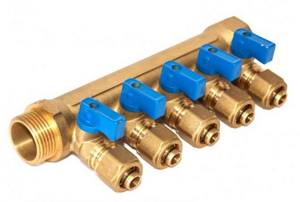
If a ready-made brass manifold is quite expensive, then you can spend much less money on a homemade one. To build such a structure you will need tees and fittings. They are connected to each other using linen tow or a liquid fixative as a cushioning material. The parts must be connected according to the assembly diagram. An example can be seen in the picture below.
After the collector is assembled, it must be tested. It is difficult to make the connection correctly, so the likelihood of leaks is high.
From a profile pipe
Making a collector from pipes with different cross-sections is the most difficult, since it will require welding work. This model can be called the most “sophisticated”. It is suitable for heating large areas and can have many pipe connections. Often such samples are equipped with a hydraulic arrow.
The following samples will be needed:
- profile pipe 8x8 cm or 10x10 cm;
- round pipe.
The calculation of the pipe cross-section is performed in special programs. It is necessary to set the required heating thermal power, water speed, temperature difference between supply and return.
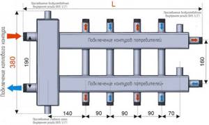
In this case, you will need to build a circuit, taking into account the number of circuits. Remember that the distance between wiring should be about 15 cm, and between collectors - at least 20 cm. A typical diagram looks like this.
Next, you need to mark a pipe with a rectangular cross-section according to the diagram, and then make holes for wiring using a gas cutter. Weld pre-prepared small parts of threaded pipes to the holes. The block is ready, all that remains is to weld the brackets to it, prepare it and paint it.
Operating principle of the collector system
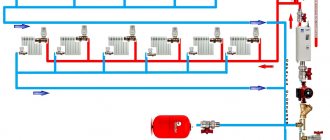
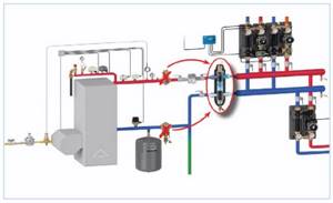
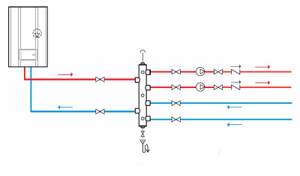
The collector system operates on the following principle: the coolant heated by the boiler, using a circulation electric pump installed between the supply and return lines, enters the collector distribution comb, to the output fittings of which the heating circuits are connected. The overall temperature of the coolant in all circuits is set by a thermostat located on the inlet fitting of the supply comb, and each outlet to the loop is equipped with a flow meter, with the help of which the volume of coolant flowing through the circuit is manually set.
After passing through the circuits, the cooled coolant enters the return line and is pushed by an electric pump to the boiler, in which it is heated. Circulating in a circle, the heated liquid is returned to the supply manifold, which distributes it over individual heating circuits.
In most designs, return line distribution units are equipped with shut-off valves - this allows the installation of electric servo drives on them to automatically regulate the flow passing through the circuits.
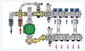
Rice. 2 The principle of collector heating
Advantages of a collector circuit for distributing water supply pipes in an apartment
In apartments, simple water pipe installation is most often performed. There is a pipe coming from the riser. Then, with the help of tees, there are branches from it to plumbing fixtures. At the same time, few people know about another type of pipe routing - manifold. And in vain, because such a system has a number of advantages that need to be discussed.
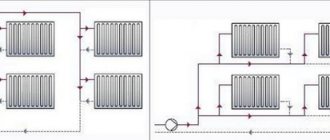
But first we need to talk about the types of wiring that exist in plumbing today. The first type is tee wiring. In such a system, all consumers are connected from one pipe using tees. It is possible to install shut-off valves in front of each consumer in case of an emergency.
Collector wiring. This system has clear advantages over the tee system. A shut-off valve is installed at the entrance of the water supply to the apartment. The difference is that each device has a separately supplied pipe. In this case, all valves are concentrated in one place.
Sometimes you can find a mixed system. This means that it contains elements of tee wiring and collector wiring. For example, water can be supplied to the washbasin and bathtub from the collector (that is, a separate pipe for each consumer), and the toilet and bidet are connected via tee wiring.
Principles of drawing up wiring diagrams
There are no uniform planning standards when drawing up wiring diagrams for a collector system. Equipment is selected for specific tasks.
But experts agree on one authoritative opinion that such a system is in no way suitable for heating apartments. This is due to the complexity of the project due to the fact that two or more risers are usually supplied to the residential premises.
And one of the prerequisites for the implementation of the scheme is the need to connect all batteries to one riser.
You may also find useful information on how to connect a heating radiator.
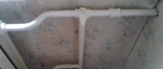
To implement a collector wiring diagram in an apartment, you will have to leave only one heat channel, having previously welded the rest - it will take on the entire load
If you weld all the other water supply channels so that one riser takes on the entire load, a closed hydraulic circuit is formed within one apartment. All heating devices located higher up the riser will be cut off from the system and will not receive the desired heat.
Residents living above will sooner or later discover the reason for this phenomenon, and the scheme will have to be forcibly redone again, paying a considerable sum.
Manifold heating distribution can be installed in new apartment buildings, provided that additional valves were installed in them during the construction stage to connect circuits of various configurations.
When arranging a collector system, you should take into account a number of key points that are also typical for other types of systems
The collector system is ideally suited for private homes.
The main thing is to adhere to the basic recommendations of professionals when designing the wiring:
- Availability of an air vent . The automated valve is placed directly on the supply and return manifolds.
- Availability of expansion tank . Its volume indicator must be at least 3% relative to the total volume of coolant. But it is also possible to use devices with a larger volume.
- Location of the expansion tank . It is installed on the “return”, placing it in front of the circulation pump along the flow of water. More details about its installation are described in our other article.
- Installation of circulation pumps on each circuit . Their location is unimportant, but due to the low operating temperature they exhibit maximum efficiency on the return line.
If it is necessary to use a comb equipped with a hydraulic compensator, an expansion tank is installed in front of the main pump, which is designed to ensure the movement of water in a small circuit.
By placing an expansion tank in front of the pump, the risk of damage to the device due to water turbulence can be significantly reduced.
The circulation pump is fixed so that the shaft is strictly horizontal. Otherwise, the very first air lock will leave the unit without lubrication and cooling.
You can read more about choosing a circulation pump in this article.
If there are additional distribution nodes in the heating system, they should not be communicating.
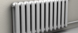
Distribution manifold system for two-pipe heating system
There are many options for collectors for heating. There are devices with a lot of parts. The supply structure contains flow meters, which are responsible for the uniform distribution of the coolant.
The design of the distribution combs controls the heating of each battery. The comb is considered the main part of the distribution structure. It is installed after the boiler and before the safety mechanism. This part looks like a pipe with pipes placed. Installation is carried out on the return and inlet lines.
DIY hydraulic collector
The hydronic collector of the heating system provides the following benefits when heating your home:
- The movement of the coolant improves and the pressure stabilizes.
- The volume of hot water on each beam of the system is regulated. Energy costs are reduced.
- Battery repairs are performed without shutting down the entire structure.
To create a comb, the following sequence of actions is performed:
- Measurements are taken between individual pipes.
- The size of the device body should be 12-17 cm larger than measured.
- A pipe is cut out and pipes are mounted on it.
- The structure is checked for leaks.
Before carrying out installation work, it is worth checking the possibility of installing a comb for a particular system. Polypropylene fittings are made without reinforcement, which can affect depressurization. You can purchase a ready-made device.
To increase circulation, special pumps are installed. If the structure is mounted in a special room, then a protective box is not required. To control and dose the coolant, fittings are installed.
WATCH THE VIDEO
A safety group is installed on the distribution mechanism.
In addition, when calculating the comb element, the difference in the size of the contours should be taken into account. The collector heating system is very popular among owners of private houses.
Feed and return manifold comb device
Combs are one of the main elements of the collector circuit; their main function is to distribute the coolant flow along the heating circuits. The element has a different design for lines of connected radiators and heated floors, the maximum number of involved circuits per collector does not exceed 12.
In relation to the diameters of the outlet fittings, the comb has a large cross-section (1.1 1/2 inches versus 3/4) and is connected to the main line through an end connection with elements of plumbing fittings. Typically, the pipeline is connected to the outlet fittings using compression fittings (Eurocones) - this method can be used to connect pipes made of cross-linked and heat-resistant polyethylene, metal-plastic, most often used in manifold heating systems. Combs are made of stainless steel, brass, plastic, some modifications are assembled from individual links.
Operating principle and types of solar collectors
The time has come to say a few words about the design and operating principle of the solar collector. The main element of its design is the adsorber, which is a copper plate with a pipe welded to it. Absorbing the heat of the sun's rays falling on it, the plate (and along with it the pipe) quickly heats up. This heat is transferred to the liquid coolant circulating through the pipe, which in turn transports it further through the system.
The ability of a physical body to absorb or reflect solar rays depends, first of all, on the nature of its surface. For example, a mirror surface perfectly reflects light and heat, but a black surface, on the contrary, absorbs it. That is why a black coating is applied to the copper plate of the adsorber (the simplest option is black paint).
The principle of operation of the solar collector
1. Solar collector.2. Buffer tank.3. Hot water.
4. Cold water.5. Controller.6. Heat exchanger.
7. Pump.8. Hot flow.9. Cold flow.
You can also increase the amount of heat received from the sun by correctly selecting the glass covering the adsorber. Regular glass is not transparent enough. In addition, it glares, reflecting part of the sunlight falling on it. In solar collectors, as a rule, they try to use special glass with a low iron content, which increases its transparency. To reduce the proportion of light reflected by the surface, an anti-reflective coating is applied to the glass. And to prevent dust and moisture from getting inside the collector, which also reduce the throughput of the glass, the housing is made sealed, and sometimes even filled with inert gas.
Despite all these tricks, the efficiency of solar collectors is still far from 100%, which is due to the imperfection of their design. The heated adsorber plate radiates part of the received heat into the environment, heating the air in contact with it. To minimize heat loss, the adsorber must be insulated. The search for an effective way to thermally insulate an adsorber led engineers to the creation of several types of solar collectors, the most common of which are flat and tubular vacuum.
Flat-plate solar collectors
Flat solar collectors.
The design of a flat solar collector is extremely simple: it is a metal box covered with glass on top. Mineral wool is usually used to insulate the bottom and walls of the housing. This option is far from ideal, since heat transfer from the adsorber to the glass through the air inside the box cannot be ruled out. With a large temperature difference between inside and outside the collector, heat loss can be quite significant. As a result, a flat solar collector, which functions perfectly in spring and summer, becomes extremely ineffective in winter.
Design of a flat solar collector
1. Inlet pipe.2. Protective glass.
3. Absorption layer.4. Aluminum frame.
5. Copper tubes.6. Heat insulator.7. Outlet pipe.
Tubular vacuum solar collectors
Tubular vacuum solar collectors.
A vacuum solar collector is a panel consisting of a large number of relatively thin glass tubes. An adsorber is located inside each of them. To prevent heat transfer by gas (air), the tubes are evacuated. It is precisely due to the absence of gas near the adsorbers that vacuum collectors are characterized by low heat loss even in frosty weather.
Vacuum manifold device
1. Thermal insulation.2. Heat exchanger housing.3. Heat exchanger (collector)
4. Sealed plug.5. Vacuum tube.6. Capacitor.
7. Absorbing plate.8. Heat pipe with working fluid.
Installing a comb in the heating system
The primary task is to check the distribution manifold for tight connections. The installation is implemented according to the design scheme. Depending on the material used to manufacture the main unit, the connection conditions are determined.
The choice of connection technology depends entirely on the modification of the device used.
In addition to maintaining the level, during installation you must follow the following rules:
- electric and gas boilers are connected to the upper or lower pipes;
- a circulation pump is mounted at the end of the structure;
- the circuits can be connected at the top or bottom of the comb;
- indirect heating devices and boilers operating on solid fuel must be connected to the distribution group on the side;
- the entire hydraulic separation unit for the underfloor heating system is placed in a protective box - this reduces the risk of damage to the constituent elements of the collector.
At the final stage, it is necessary to carry out a control start-up of the heating in order to timely identify hidden or obvious deficiencies in the design.
Solar heating: pros and cons
If we talk about using solar energy for heating, then you need to keep in mind that there are two different devices for converting solar energy:
- Solar panels. They produce exclusively electric current. But you can already use it to ensure the operation of any electrical equipment, including the operation of heating devices.
- Solar collectors. These devices heat the liquid (coolant) and can be directly connected to the heating system, and can also be used to heat water for domestic needs.
Both options have their own characteristics. Although it must be said right away, whichever one you choose, do not rush to abandon the heating system that you have. The sun rises, of course, every morning, but your solar cells will not always get enough light. The most reasonable solution is to make a combined system. When the sun's energy is sufficient, the second heat source will not work. This way you will protect yourself, live in comfortable conditions, and save money.
If there is no desire or opportunity to install two systems, your solar heating should have at least a double power reserve. Then we can say for sure that you will have warmth in any case.
Advantages of using solar energy for heating:
- A safe and absolutely “clean” source of energy.
- Reduced heating and hot water costs.
- You are independent of the state of the economy: the sun always shines, both in crisis and in times of prosperity.
- The sun does not require money for its energy. Another thing is that the state can impose taxes on the owners of solar installations. But so far this has not happened - solar energy is free.
Flaws:
- Dependence of the amount of incoming heat on the weather and region.
- For guaranteed heating, you will need a system that can operate in parallel with a solar heating system. Many heating equipment manufacturers provide this possibility. In particular, European manufacturers of wall-mounted gas boilers provide for joint operation with solar heating (for example, Baxi boilers). Even if you have installed equipment that does not have this capability, you can coordinate the operation of the heating system using the controller.
- Solid financial investment at the start.
- Periodic maintenance: tubes and panels must be cleaned of adhering debris and washed from dust.
- Some of the liquid solar collectors cannot operate at very low temperatures. On the eve of severe frosts, the liquid must be drained. But this does not apply to all models and not all liquids.
Now let's take a closer look at each type of solar heating element.
What is a collector and how does it function?
The term “manifold” refers to a unit or device that is a piece of pipe with many outlets, making it look like a comb (hence the name “comb”). Through it, coolant liquid flows with different temperatures can be mixed until the specified parameters are reached, and then distributed along the circuits.
Separate comb
The system must have two such combs - on the supply pipe and on the return pipe. One receives coolant from the boiler and doses it, directing it to the circuits, and the second collects these flows on the way back and returns it to the boiler for additional heating.
The collector unit consists of two combs
- To control the flows on the combs there are fittings with metering valves. A pressure gauge is connected to them to monitor pressure. In some systems, a pump may also be turned on, through which water circulates in the system.
- The flow part of the comb has a slightly larger diameter than that of the main pipeline (it is determined by calculation). When the coolant enters the collector, the speed of the coolant decreases, which makes it possible to redistribute the flow or change the trajectory of its movement.
- Radiator heating and heated floors must have their own separate collectors, to which branches leading to one or another room or to different floors are connected.
- If necessary, one branch can be closed, or simply reduced the temperature of the coolant supplied to it, without affecting the characteristics of other circuits.
Note! As an option, you can install an assembly like the one in the photo, which is called a hydraulic distributor.
The collector unit consists of two combs
On a note! If repairs are required, it is enough to turn off only one circuit without touching the others. This will also reduce the operating costs of the system when no one lives in the room (for example, a guest room), and there is no need for constant heating.
Features of coolant distribution
The heating distribution unit is always individual in structure, since standardization is inappropriate here. The modification can be anything and must be adapted to the technical device and other features of the system, which may contain completely different complete variations of devices and fittings.
The simplest option is when there are no devices at all, but only a simple comb with two or three outputs. In such a system, it is only possible to turn off one of the circuits, but control of the volume and temperature of the coolant fluid is not provided.
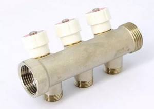
Simple comb with three outputs
Yes, this is not always necessary. For example, in a small cottage heating system, in which heating of the coolant is provided by a gas-fired boiler. Usually he himself performs the functions of the controller, since almost all modern models are equipped with the appropriate devices.
Heating boilers for private homes (especially gas floor-standing ones) are popular in different countries of the world, including here. All these products have a similar appearance, but still differ in characteristics. In order to purchase the best option, in a special article we will consider the main criteria for choosing boilers.
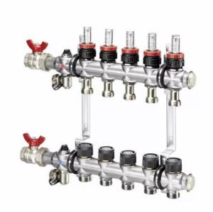
In large branched systems, advanced manifolds are installed, which are equipped with a full set of control valves: thermostat, sensor and pressure regulator, mixing valves and air vents. The equipment varies, and the cost of the unit depends on it.
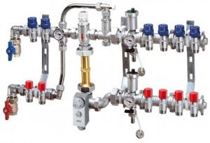
Manifold with improved equipment
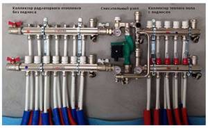
In a house that, in addition to radiator heating, also has a heated floor, the distribution unit may look like in the photo: on the left is a collector for radiator circuits, on the right for heated floors, and in the middle is a mixing unit, the center of which is the circulation pump.
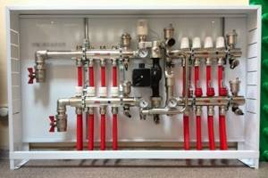
Coolant distribution unit for radiators and underfloor heating
If the house has several levels, collector units are installed on each floor. The installation location is chosen such that it is possible to provide the same length of supply to each radiator.
The length of the circuit should not exceed 120 m - with a larger value, an additional collector group is formed. In addition, longer routes should be equipped with a pump, since the coolant in them will cool faster.
Depending on the specific conditions, combs are selected according to the type of connection. It can be upper or diagonal, but preference is often given to the lower one, in which the wiring can be hidden in the structure of the floor or baseboard. The unit is usually hidden in a special cabinet, or a niche is built in the wall to install it.
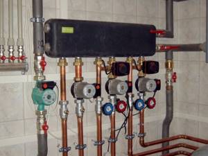
Each circuit has its own pump
As for hydraulic arrows: they are installed on large objects with a large number of circuits, when it is necessary to compensate for losses not only of temperature, but also of coolant volume. This is achieved due to its secondary circulation, but this will only be possible if each circuit has its own pump.
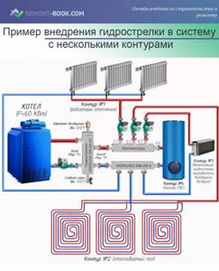
An example of introducing a hydraulic arrow into a system with several circuits
In fact, through one hydraulic switch it is possible to arrange several nodes independent from each other, each of which has its own operating settings. But even a regular “unsophisticated” manifold allows you to maintain stable pressure in the system even when several taps are open at once.
What to look for when choosing
The cost of a separate comb or a complete collector depends not only on the power of the device or its equipment, but also on the material of manufacture. The most expensive are stainless steel products, brass ones are slightly cheaper.
The most affordable are combs made of polyethylene (connected with fittings) and polypropylene (soldering is used for connections). They are lightweight and easy to install, but the inability of polymers to withstand high temperatures is a significant drawback that limits the scope of application of the products.
On a note! The choice of one option or another is made not only for cost reasons, but also depending on what pipes are installed. It is ideal when all elements of the system are assembled from the same type of material - and even better if they are also from the same manufacturer.
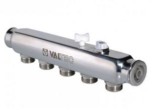
Stainless steel
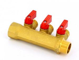
Brass
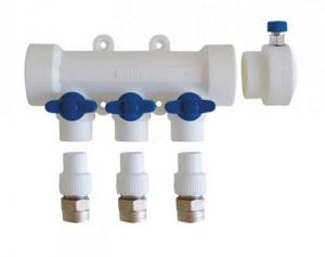
Polypropylene
In addition to the outlets for the circuits, the comb has a hole for connecting to the pipe and a plug in which a valve can be mounted to release air. By removing it, one product can be attached to another, making one solid block, without using adapters.
After you decide on the material, you should pay attention to the technical parameters of the products. Among them are not only the number of connection circuits, but also:
- Bandwidth.
- Maximum permissible pressure (working).
- Completeness of control devices and degree of automation.
- Center-to-center distance of the contour.
- Minimum and maximum temperature (operating).
Manifold installation cabinet
Complete collector units can also be sold complete with a cabinet for installation. But in principle, you can assemble not only the cabinet yourself, but also the collector itself.
Prices for collectors for water supply and heating systems
Manifolds for water supply and heating systems
Video - Collectors for radiators and heated floors
Heating collectors: types of devices
There is no standard heating manifold configuration. The device can be made in any modification, which allows it to be adapted to a variety of heating systems with different types of devices and the number of circuits. The comb has from 2 to 12 circuits; the price of the heating collector depends on this indicator. During operation, the number of involved branches may vary.
According to technical characteristics, heating distribution units can be divided into the following types of collectors: solar, with a hydraulic arrow and radiator. Based on the number of system elements, simple and advanced models are distinguished. The first option is not equipped with additional devices to control and adjust the operation of the device. It is represented by a simple comb with several branches, each of which can be turned off. In such a system, control over the temperature and volume of the coolant is not assumed.
Improved products are equipped with pressure and temperature regulators, pressure sensors, water supply control units, thermostats for automatic pressure adjustment, electronic mixers and valves for regulating the supply of cold and hot water, air vents for releasing air bubbles from pipes.
Note! The configuration of the collector unit may vary depending on certain system requirements, which affects the functionality and cost of the installation.
Manifolds for radiators and heated floors
The difference between a floor collector and a radiator collector is in the design associated with the difference in operating temperatures and the lower hydraulic resistance of the radiator elements. The design of the block for connecting underfloor heating is much more complex; it includes a large number of control water fittings and a circulation pump for multi-circuit systems.
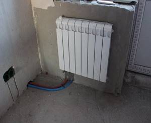
The standard manifold block for household radiators has a simple design: it consists of supply and return manifolds of large cross-section, from which come fittings for connecting pipes going to the radiators. The device usually does not have any adjusting, tuning valves or other complex devices, so connecting and installing it does not cause difficulties for most homeowners. Heating radiators are connected to the unit through pipes running in the floor and connected from below at one point; to place a straight pipeline it is not necessary to make a screed; it can be laid in a groove cut or knocked out in the slab.
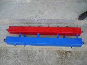
A typical collector block is a technically complex element with a large number of adjustments and settings; often a circular electric pump is installed in the system. When installing the block, you should distinguish between the forward and reverse feed combs; for convenience, they are marked with red and blue paints, respectively. Also, adjustable flow meters with a transparent cap and marked divisions indicating the volume of liquid passing through them are most often placed in a straight line; it is marked with an internal red indicator head.
Typically, the maximum value of the transmitted flow does not exceed 5 cubic meters per hour (corresponding to division 5 on the cap), the minimum mark is 0.5. If the indicator heads are in the upper part, then when the water flow passes through the supply comb, the indicator lowers and shows the volume of liquid passing through. Sometimes the heads are located at the bottom, in this case the flow moves in the opposite direction from the heating circuit to the comb and, accordingly, the flow meters are installed in the return flow bar.
If a circular electric pump is installed in the collector block, then its impeller directs the flow from the output comb to the supply housing - thus mixing cold water from the return line into the coolant heated by the boiler to lower its overall temperature.
The standard block provides space for the location of the thermostat sensor, there are exhaust valves for bleeding air in the supply and return combs, valves are installed in place of which there are seats for servos that perform automatic control of operating modes.
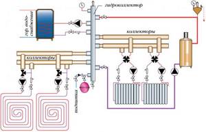
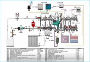
Rice. 11 Collector heating system for an individual house, Gidrostrelka - installation and connection diagram
- You might be interested in what the pressure in the heating system should be.
Popular manufacturers of heating system manifolds
Popular manufacturers of high-quality collectors are the companies Rehau and Oventrop, which provide the maximum warranty period for their products. Consumers note the high quality of products, reliability, ease of installation and long service life.
Oventrop specializes in the production of universal manifold models that are ideal for radial heating, underfloor heating and water supply systems. High-quality stainless steel is used to manufacture products. The collectors can withstand temperatures up to 120 °C. The cost of products varies from 2.5 to 28 thousand rubles.
The most popular among consumers are radial heating combs made of stainless steel. Such collectors are designed for a pressure of 10 bar and a system temperature of up to 100 °C. You can buy the product for 1.7 thousand rubles. Distribution manifolds for underfloor heating made of tool steel are produced with valve accessories, with the help of which the operation of the system is regulated. The manifolds are designed for pressures of 6 bar and temperatures up to 70 °C. You can buy a double-circuit product for 3.5 thousand rubles.
Rehau distribution manifolds have a more attractive appearance, which makes it possible to mount them on the wall in an open manner. Products are made of stainless steel and brass. The company produces improved models equipped with flow meters, taps, valves and a pump. You can purchase the device for 1.5-32 thousand rubles, which depends on the number of circuits of the product.
The HKV comb for underfloor heating systems, made of brass, is very popular. The manifold is designed for temperatures up to 80 °C and operating pressure up to 6 bar. The cost of a double-circuit product is 6.5 thousand rubles.
The Rehau HLV distribution manifold can be used for radial heating. The brass product can withstand temperatures of 80 °C and pressure of 8 bar. The price of the model is 4 thousand rubles.
The domestic manufacturer North deserves attention, offering high-quality hydraulic manifolds at an affordable price, which varies between 2.5-20 thousand rubles. Products are made primarily of steel. Pexay heating collectors are characterized by an ideal price-quality ratio, the price of which averages 5-12 thousand rubles.
Installation and connection of the distribution comb
When installing and connecting the distribution manifold for heated floors, it is useful to follow the following rules:
- Due to their large length, filling the comb with all the loops is done with a small flow of liquid to avoid airing; the procedure usually takes 1.5 - 2 hours for floors with an area of 100 square meters.
- After filling the coolant into the system, all circuits except one are closed - water is passed through it and drained through the drain valve, ensuring that there is no air in the loop. Do the same with other circuits, sequentially pumping and draining water through them.
- After filling all the loops with coolant, leave one loop connected, turn on the circular electric pump and drive water through it, opening the air bleed valve.
- The operation is repeated for each individual circuit, pumping the liquid for 5-10 minutes.
- Upon completion of the run, all circuits are opened, the electric pump and boiler are turned on for complete de-airing through automatic exhaust valves, which can last for several hours.
To ensure the same temperature in all loops, flow meters are used, the setting principle of which is as follows: the greater the length of the loop, the greater the flow of water should be passed through it. For example, if the length of one loop is 100 meters, the second is 60, and the third is 40, then to set up the loop with the greatest length, unscrew the flow meter nut until it stops, maximizing the through channel, and visually determine the flow rate using the mark.
In loops with a shorter length, the flow rate is set based on the maximum reading of the longest loop in the appropriate proportion. For example, if the longest 100-meter branch has a maximum flow rate of 2 units, the 60-meter branch is set to 1.2, and the 40-meter branch is set to 0.8.
Rice. 15 Collector heating system for an individual house from the popular manufacturer Valtec - features and types
What can you make a solar system from yourself?
First, you need to understand what operating principle a solar water heater uses. The internal structure of the block contains the following components:
- frame;
- absorber;
- a heat exchanger within which the coolant will circulate;
- reflectors to focus the sun's rays.
The factory solar water heating collector works as follows:
- Heat absorption - the sun's rays pass through the glass located on top of the body or through vacuum tubes. The internal absorbent layer in contact with the heat exchanger is painted with selective paint. When sunlight hits the absorber, a large amount of heat is released, which is collected and used to heat water.
- Heat transfer - the absorber is located in close contact with the heat exchanger. The heat accumulated by the absorber and transferred to the heat exchanger heats the liquid moving through the tubes to the coil inside the heat storage tank. Water circulation in the water heater is carried out by forced or natural means.
- DHW - two principles of heating hot water are used:
- Direct heating - hot water after heating is simply discharged into a thermally insulated container. In a monoblock solar system, ordinary household water is used as a coolant.
- The second option is to provide domestic hot water with a passive water heater based on the principle of indirect heating. The coolant (often antifreeze) is sent under pressure to the solar collector heat exchanger. After heating, the heated liquid is supplied to a storage tank, inside of which a coil (playing the role of a heating element) is built, surrounded by water for the hot water supply system. The coolant heats up the coil, thereby transferring heat to the water in the container. When the tap is opened, heated water from the heat-storing tank flows to the water collection point. The peculiarity of a solar system with indirect heating is its ability to operate throughout the year.
The operating principle used in expensive factory-made solar systems is copied and repeated in do-it-yourself collectors.
The working designs of solar water heaters have a similar structure. They are only made from scrap materials. There are schemes for the production of collectors from:
- polycarbonate;
- vacuum tubes;
- PET bottles;
- beer cans;
- refrigerator radiator;
- copper tubes;
- HDPE and PVC pipes.
Judging by the diagrams, modern “Kulibins” prefer homemade systems with natural circulation, thermosiphon type. The peculiarity of the solution is that the storage tank is located at the top point of the hot water supply system. Water circulates through the system by gravity and is supplied to the consumer.
Modifications of collector units
Before you begin assembling the collector assembly, it is necessary to determine its functional load. The equipment can be installed in several sections of the heating main. Based on this, the necessary equipment, dimensions and level of automation of the work cycle are selected.
In fact, for the full operation of such a node, two devices are needed. Using a comb, the coolant is distributed along the contours of the central supply pipeline. The return collector channel is represented by a collection mechanism and the point of departure of the cooled liquid into the boiler.
The collector heating circuit is selected based on the calculation of the required functionality and installation location. The choice of material for making the device does not affect the number of significant mechanisms
Installation of a homemade distribution group may be required when installing water-heated floors or for preparing standard heating with radiators.
Distinctive features of both options are their sizes and components:
- Boiler room. The welded manifold group is made of pipes with a diameter of up to 100 mm. A circulation pump and shut-off valves are installed on the supply side. The return ring is equipped with shut-off ball valves.
Each of these solutions provides an individual installation scheme. Correct installation of all elements can be carried out only after detailed calculations of all operating point parameters.
The comb can be made of the same material as the pipeline. If it is different, adapters will be used to connect the collector
There are also differences in the required number of circulation pumps. In the boiler room, each line is equipped with this device. For heated floors, only one installation is provided.
Selection of pipes for the heating system
When creating a manifold wiring diagram for heating a low-rise residential building or other private building, it is necessary to take into account the method of laying pipes throughout the house. If the piping will run under the floor, in a concrete screed, then it is recommended to buy heating pipes in coils so as not to make connections in the floor, as mentioned above.
Plastic pipes must have sufficient flexibility, the pipe material must not be subject to corrosion and the influence of aggressive environments, must not be destroyed at low or too high temperatures, and the service life of the pipes must be extremely high.
The requirements for temperature resistance and tensile strength of pipes are determined by the performance characteristics of the installed heating system in a house or apartment. For individual development, the pressure in the pipes should not exceed 1.5 atm, and the maximum temperature regime should be in the range of 500C -750C. If the house has a “warm floor” system, then the temperature of the coolant in the pipes should not rise above 300C -400C.
Manifold for combined heating
When installing a manifold heating circuit in an apartment building, the pressure in the pipes will always be high, and the pipe material must withstand ≥ 10-15 atm. at a coolant temperature of up to 110-1200C. Therefore, when laying heating pipes in an apartment building, it is recommended to use corrugated pipes made of stainless steel, rather than metal-plastic or PVC products. As a working example, we can cite the Kofulso brand of pipes, which can withstand pressures of more than 15 atm. at coolant temperature ≥ 1100C. The pressure force that causes the destruction of this material is 215 kgf/cm², which is an excellent indicator.
Collector wiring in the apartment
The bending radius of such stainless pipes is equal to their diameter, which allows them to be laid in almost any place and with any bend, without fear that the pipe will leak at the bend. Connections in such piping are made using special fittings, and the twist points are fixed with a lock nut, which ensures the tightness of the connection of corrugated pipes with silicone seals.
But stainless steel is not the cheapest material, and when installing manifold pipes in a two- or three-story building, such a project will be quite expensive. Therefore, it makes sense to use pipes made of cross-linked polyethylene, for example, PE-X brand. These pipes, like other PVC products, are sold in coils, the length of one pipe is 200 meters, the material is able to withstand pressure up to 10 kgf/cm² at a coolant temperature in the system up to 950C. A short-term increase in temperature up to 1100C is allowed.
Corrugated stainless steel pipes
Water pipes made of cross-linked polyethylene are also connected to each other using special fittings in the form of plastic or metal (bronze, brass, copper) fittings with a locking ring, which fits tightly onto the pipe and seals it tightly. The advantage of such pipes is that cross-linked polyethylene has a mechanical memory, that is, assembly is carried out according to the following scheme: the pipe is stretched with a special extender so that a fitting can be inserted, and after some time (up to a minute) the pipe takes on the original diameter and tightly presses the fitting. Additionally, tightness is ensured by a locking ring.
Selecting Basic Elements
When designing a heating system, it is advisable to choose branded distribution units. Due to the large assortment, you can easily select a comb for the specific parameters of the system, thereby ensuring its reliable operation.
The main criteria when choosing pipes are increased burst strength, heat resistance and corrosion resistance. In addition, the pipes must have sufficient flexibility to be able to be laid at an angle.
When purchasing products, it is advisable to choose pipes that are manufactured in coils. The use of solid elements will make it possible to avoid joints, which is important during closed installation in a floor screed.
Pipes for private houses
When designing heating, it must be taken into account that the pressure in the system will reach approximately 1.6 atm. In this case, the coolant temperature is:
- for heated floors - +35...45°С;
- for heating batteries - +55...75°С.
For heating systems of cottages it is absolutely not necessary to choose stainless corrugated sections. Most owners are limited to laying pipelines made of cross-linked polyethylene with PEX marking. These pipes are connected using tension fittings, resulting in a seamless connection.
When using metal-plastic pipes, the connection is made using union fittings. That is, a removable connection is obtained, and taking into account SNiP, it is prohibited to “solidify” it.
Pipeline for multi-storey apartments
If heating is installed in a multi-storey building, then it is necessary to take into account that the pressure in this system will be 12-17 atm, and the coolant temperature reaches +130°C. We must not forget that the arrangement of this system can only be done on the ground floor.
The best option for a multi-story building is to use corrugated pipes made of stainless steel. An example is the products of the Korean company Kofulso. These pipes can operate at a pressure of 17 atm. with temperatures up to +130°C.
Collector Stanilova
Engineer Stanislav Stanilov presented the world with the most versatile solar collector design. The main idea of using the device he developed is to obtain thermal energy by creating a greenhouse effect inside the collector.
Collector design
The design of this collector is very simple. Essentially, this is a solar collector made of steel pipes welded into a radiator, which is placed in a wooden container protected by thermal insulation. Mineral wool, polystyrene foam, and polystyrene can be used as thermal insulation materials.
A galvanized metal sheet is placed at the bottom of the box, on which the radiator is mounted. Both the sheet and the radiator are painted black, and the box itself is covered with white paint. Of course, the container is covered with a glass lid, which is well sealed.
Materials and parts for manufacturing
To build such a homemade solar collector for heating a house you will need:
- glass that will serve as a lid. Its size will depend on the dimensions of the box. For good efficiency, it is better to select glass measuring 1700 mm by 700 mm;
- glass frame - you can weld it yourself from corners or put together from wooden planks;
- board for the box. Here you can use any boards, even from dismantling old furniture or plank floors;
- rental corner;
- coupling;
- pipes for radiator assembly;
- clamps for attaching the radiator;
- galvanized iron sheet;
- radiator inlet and outlet pipes;
- tank with a volume of 200−300 liters;
- aqua chamber;
- thermal insulation (sheets of polystyrene foam, expanded polystyrene, mineral wool, ecowool).
Stages of work
Stages of making a Stanilov collector with your own hands:
- A container is made from boards, the bottom of which is reinforced with beams.
- A heat insulator is placed at the bottom. The base must be especially carefully insulated to avoid heat leakage from the heat exchanger.
- Afterwards, a galvanized plate is placed at the bottom of the box and a radiator is installed, which is welded from pipes, and secured with steel clamps.
- The radiator and the sheet underneath are painted black, and the box is painted white or silver.
- The water tank should be installed under the collector in a warm room. Between the water tank and the collector you need to install thermal insulation to keep the pipes warm. The tank can be placed in a large barrel into which expanded clay, sand, sawdust, etc. can be poured. and thus insulate.
- An aqua chamber must be installed above the tank to create pressure in the network.
- Do-it-yourself solar collector installation should be done on the south side of the roof.
- After all the elements of the system are ready and installed, you need to connect them into a network with half-inch pipes, which must be well insulated in order to reduce heat loss.
- It would be a good idea to build a controller for the solar collector with your own hands, since factory devices do not last long.
How to choose
Before choosing to use a distribution manifold in the heating system of your home, you must take into account certain circumstances associated with the purchase and related installation work, namely:
- High price. There is no doubt that this technology is very high quality, convenient, and can also increase the productivity of heating devices many times over, but at the same time it is also the most expensive among all currently existing devices. This is due both to the use of the highest quality metal, and to the additional acquisition of various parts, fittings and equipment, from which the following nuance emerges;
- Circulation pump and other devices. The collector system will function only if there is a circulation pump, additional fittings for each circuit, taps, plugs and a selected collector cabinet;
- Installation work. Installing such a system is quite complicated and requires a certain amount of time and financial resources, especially if the connection is made to a “warm floor” system. All this can bring a certain discomfort if the house is already equipped and not at the construction stage.
If the above points are not paramount for you, and you are ready to come to terms with them, you can proceed to the direct selection of a heating distribution manifold. You should pay attention not so much to the material from which it is made, but to the technical parameters, which are listed below:
- the maximum permissible system pressure that the equipment can withstand;
- approximate calculation of electrical energy consumption by the device;
- the number of circuits corresponding to all heating devices in the house;
- distribution manifold throughput level;
- the potential possibility of adding the necessary circuits in case of increasing heating devices;
- the presence of a variety of automatic auxiliary devices;
- reputation of the manufacturer.
Popular articles DIY Christmas tree costume for a girl (photo, video)
It will be just great if you understand all of the above, but as practice shows, the most correct calculation of all parameters can only be made by specialists in this field, who will help not only with the choice, but and with the subsequent establishment of the system.
Compalar distribution manifold
Despite the fact that hardware stores have a large assortment of distribution manifolds of different sizes, it can sometimes be difficult to select a device exactly for your heating system. Either the number of contours or their cross-section may not match. As a result, you will have to make a monster from several collectors, which will clearly not have the best effect on the efficiency of the heating system. And such pleasure will not be cheap.
At the same time, you should not believe the stories of “experienced” people that the system can work perfectly even with a direct connection to the boiler. This is mistake. If your heating system has more than three circuits, then installing a distribution manifold is not a whim, but a necessity.
But if there is no distribution manifold on sale that suits your parameters, you can easily make it yourself.
Pipeline laying options
The main pipe laying schemes during installation are zigzag and spiral volute, the latter provides more uniform heating and is considered the best in efficiency. When laying pipes, a certain distance between sections must be maintained; it depends on the layout and thickness of the screed; its typical value for the usual thickness of the cement-sand layer is in the range of 150 - 200 mm.
The distribution manifold is the main unit in an individual heating system containing two or more underfloor heating circuits; it performs the functions of distributing and mixing the coolant to reduce its temperature. During installation, a pipeline made of cross-linked or heat-resistant polyethylene is placed under a screed in the form of a zigzag or snail and connected to the combs using Eurocones, which ensure a quick and tight connection.
System installation
It is necessary to install a collector system at the stage of design and construction of a private house. Because after laying the finishing floor covering, installing this system is extremely impractical and labor-intensive. The only installation method is open mounting.
Comb installation
For horizontal wiring of the heating system, a manifold cabinet will be required to install control equipment, a circulation pump and a distribution unit. It is placed in niches of rooms that are protected from moisture. As a rule, a place in the pantry, dressing room or hallway is equipped for this.
When organizing the heating of a two-story house, it is necessary to place several collector groups, one per floor. Additional distribution combs will make it possible to create approximately the same length of the circuit.
As an option, you can choose a scheme where the first group is responsible for supplying coolant through separate circuits, and the other is the main element during the installation of a “warm floor”.
The number of inputs and outputs of the distribution unit should always be equal to the number of heating devices located on the floor. For each room it is necessary to lay its own branch, which, by connecting several radiators, can implement a dead-end or associated system.
To reduce the cost of connecting heating batteries, a “pass-through” system is used. During installation of this circuit, several radiators connected in series are perceived as a single element.
Laying methods
During collector wiring, as a rule, the method of installing the pipeline in a cement screed is used. In this case, the thickness of the screed is made in the region of 60-70 mm, this is quite enough to “solidify” the wiring. However, taking into account SNiP, only solid connections can be installed in a cement base, for which metal-plastic pipes with a cross-section of 15 mm are often used. Due to the fact that they are elastic, the pipeline can be easily laid under the floor.
If you decide to fill the pipeline with a screed after pressing the system, you must first wrap the pipes with thermal insulation. This layer will make it possible to minimize the risk of damage to the pipeline under the influence of thermal expansion, since the pipes will begin to “rub” not against the cement screed, but against the thermal insulation. It is necessary to lay plywood on top of the screed, and then make the finishing floor covering.
The pipeline can also be routed to the heating radiators from above, for example, under a suspended ceiling. Some experts often lay pipes using the external method, installing them along the walls and masking them with decorative skirting boards. However, this installation option will inevitably entail an increase in the length of the pipeline.
It is not recommended to place pipes under door openings: during the installation of the door threshold, the pipe may be damaged during drilling. If pipes need to be laid through walls, then to prevent their deformation during shrinkage of the house, sleeves are inserted into the holes.
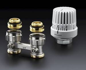
Shut-off valves must be installed separately on each distribution circuit coming from the comb. To allow accumulated air to be released, install:
- on heating radiators - Mayevsky taps;
- on the comb there are air outlet valves.
Due to the fact that each heating circuit coming out after the distribution unit is an independent system, it is convenient to use it when organizing “warm floors”.
The collector heating circuit is ideal in terms of efficiency. The autonomous supply of water heated from the boiler to each battery makes it possible to create a comfortable microclimate in each individual room. The high price, unlike traditional heating systems, slightly restrains the popularity of this type of home heating, but if money allows, then heating using a collector system is the best option.
Pros and cons of the collector-beam system
Among the undeniable advantages of installing a collector system, it is worth highlighting:
- Ease of use . Due to the fact that each element is controlled independently, the consumer has the opportunity to set the temperature anywhere in the house. And as needed, it’s easy to turn off one or a group of heating devices in the room. At the same time, the temperature in other rooms will remain the same.
- Possibility to use small diameter pipes . Since each branch leading from the collector feeds only one device, small-diameter pipes that can be easily hidden in a screed can be used to lay it.
- Maintainability . If problems are detected, it will be easy to disconnect any section of the pipeline without interrupting the operation of the entire system.
To form several circuits with different parameters, for example: pressure drops or different media temperatures, distribution combs with a hydraulic compensator function are used.
The hydraulic arrow is a capacious pipe, to the outputs of which a number of circuits with independent circulation are connected.
The water heated by the boiler enters the hydraulic arrow. Circulating inside the device, water is taken at different distances from the taps and redistributed along the contours.
At the insertion points of each circuit after the hydraulic arrow, its own values of pressure drop and media temperature will be set
Due to the fact that the heated coolant delivers heat to the batteries with less loss, the efficiency of the system increases. This makes it possible to reduce the boiler power and thus save fuel consumption.
The heating system, the main element of which is the collector, is not without drawbacks.
These include:
- Pipe flow . When compared with a series connection, the pipe consumption when laying a collector system is two/three times higher. The difference in costs is determined by the size of the area involved.
- The need to use circulation pumps . The installation of independent circuits is not complete without the installation of circulation pumps. This entails additional costs.
The weak link of the collector system is its energy dependence. So even with the boiler running, in the event of a power outage, the pipes will remain cold. For this reason, such systems are not recommended for use in areas where power outages are common.
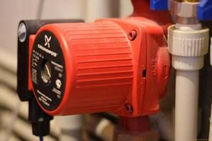
The circulation pump ensures forced movement of the coolant in a system made of pipes with a small diameter, in which the total hydraulic resistance is high
When laying contours in a floor screed, it is worth considering that any connection is a potential leak point. And if a defect occurs, the monolithic concrete will have to be opened to eliminate it. And this is already a very troublesome and costly undertaking.
Therefore, the connections of the collector system networks are located exclusively above the floor level. Most often they are confined to the manifold cabinet.
Purpose of the heating manifold
The absence of a distribution manifold in a water heating system can lead to the fact that water may flow unevenly into different circuits of the system. As a result, you will have a hot floor and cold radiators, or vice versa.
This may occur because several heating system circuits can be connected to one boiler outlet. The liquid flows unevenly through such connections, as a result of which part of the premises will not have enough heat. But the efficiency of the heat supply system depends on the amount of coolant passing through the pipes, the volume and speed of its movement.
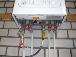
pipes coming from the boiler
Some home owners try to solve this problem by installing additional pumps and control valves. But this only complicates the system and does not always lead to uniform distribution of the coolant.
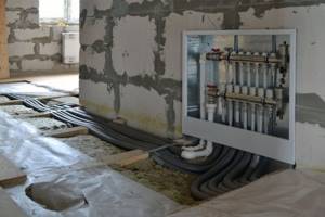
Features of installation of the collector system
Installation of heating systems is carried out before finishing work on laying floor and wall coverings; the pipeline running along the floor is tied to a strong metal mesh and filled with a screed located on the insulation layer.
Apartment house
The implementation of collector heating in a residential apartment building is practically not used in everyday life, this is primarily due to the presence of radiator heating in buildings, in which all rooms in the apartment are heated by radiators. Laying circuits for heating rooms through floors is associated with significant financial costs and is ineffective; moreover, a comb is not required for laying a small number and short length of loops. A significant factor that makes the installation of collector heating in an apartment building useless is the imbalance and violation of the temperature regime of the entire house system, as a result of which penalties and dismantling of the installed heated floor are possible.
Cottage
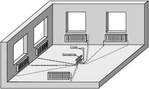
Collector combs are the main elements in organizing heating of country houses and cottages; they are usually placed in the wall of rooms located in the center of the house on each floor, connected to a riser built into them.
To do this, during the construction stage, a recess is placed in the wall in which the comb is placed; to improve the aesthetic appearance, a manifold cabinet with closing doors is placed in the place of insertion.
One circuit is used for each room; if there are several radiators in the room, they are connected in series using a single-pipe passing or pass-through circuit (Leningrad). Several small circuits are installed if the area of the premises is large and the maximum length of the pipeline does not ensure its coverage at a given pitch.
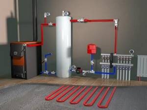
Rice. 14 Combined heating system
Collector heating
In collector heating, each device has its own independent supply. This makes it possible to regulate the temperature of an individual radiator or completely exclude it from the coolant circulation (turn it off). The node of the system is precisely the collector, which has the form of a comb. It includes the main supply and return lines, and secondary piping exits. The collector water heating system can be either single- or double-circuit.
Pros:
- Ability to configure optimal indoor air parameters. That is, each heating device in the circuit is controlled independently and centrally. If the room becomes hot for some reason (many guests came, an additional heat source appeared, etc.), the temperature in the radiator can be reduced without disturbing the microclimate in other rooms of the house. In general, different temperatures can be created in different rooms. This allows you to save on energy resources.
- Application in the installation of small diameter pipeline systems. Each branch that comes out of the collector feeds one heating device or a small group. It follows from this that the pressure in the pipelines is not very high (but acceptable). The small diameter of the pipelines determines the good aesthetics of the heating system. Its elements do not stick out and do not clutter up the room.
Minuses:
- High consumption of consumables during installation (in contrast to the sequential circuit for connecting heating devices in the heating system). The more complex the connection configuration of individual elements, the smaller the savings.
- The collector assembly itself does not look aesthetically pleasing and is bulky. So that it does not catch the eye, it needs to be hidden.
- In a collector heating system, it is impossible to do without installing circulation pumps (supply and return). The force of gravity is not sufficient for normal circulation of the coolant in the circuit. The purchase and installation of circulation pumps is also not a small additional expense.
- Energy dependence. Not only will circulation pumps hit the budget, but that’s not all. An unscheduled shutdown of lights in a village can lead to a malfunction of the heating system, and in winter, to freezing of the coolant inside the pipelines. This is all due to the fact that the pumps are powered by electricity.
- Experts do not recommend installing collector heating systems in city apartments.
Manufacturers offer many different models of collectors on the construction market. Among them there are devices with a maximum set of elements. Part of the coolant supply is equipped with flow meters. Using these devices you can regulate the water flow in the circuit. This is done in order to balance the pressure in the system. Part of the coolant return is equipped with temperature sensors. Using these devices, the temperature in heating radiators is regulated. The system allows you to automatically control the heating of each heating device. Thermal sensors for the collector system can also be different. Brass elements with an inch passage are often used. Thermal sensors have plugs on the return line. This allows, if the need arises, to connect additional elements to the system.
There are people who make combs with their own hands. This is strongly not recommended. The combs must be installed by qualified specialists who have sufficient knowledge and skills and will carry out the work in accordance with the building codes and regulations in force at the time. After installation of the system, hydraulic tests are carried out. Ignoring building codes and regulations during installation leads to negative consequences, including system failures and accidents.
Popular articles Cat pillow
The location for installing the collector is determined at the design stage of the heating system. If the house has several floors, each has space for a collector block. Most often, a special niche is made in the wall for this purpose at a small height from the floor level, but so that small children or animals cannot get into it. The comb must be installed in a room with acceptable air humidity (pantry, corridor, etc.).
The device can be attached directly to the wall if it is mounted in a utility room or placed in a specially designated cabinet (meaning a metal box with a door).
Manifold wiring for heated floors
Installation of a heated floor using collector wiring is carried out similarly to a conventional water floor. You can install a heat transfer element under the floor covering and then connect it to the collector. Practice shows: it is possible to combine a collector for floor heating together with heating through radiators, but this should not be done. Multi-temperature systems.
It is worth remembering about thermal regulation: heated floors have less heat transfer, radiators have more.
The collector heating system today is the most efficient, economical, and quickly pays for itself. It is convenient, simple, and visually invisible, which makes living where it is installed as comfortable as possible.
Why do you need a collector, principle of operation
The design of this plumbing fixture is very simple. Essentially, this is a piece of large diameter pipe equipped with threaded fittings for connecting the circuits of the water system. The length of the heating comb depends on the number of connections; the main line is usually connected to the end.
What happens in the collector, where water flows from 2...10 parallel branches:
- From several lines, a coolant with various parameters - temperature, flow rate, flow rate per unit of time - enters the collection pipeline.
- In a large flow section of the comb, the speed of water movement decreases and the hydraulic resistance decreases.
- Mixing in the main chamber, different flows acquire the same temperature and speed at the outlet.
Diagram of operation of the collector pipe for collecting coolant
So, the task of the collector is to collect the coolant, equalize its parameters and send it back to the boiler along the main line. You cannot do without a comb when you need to combine several lines with different water flow rates, hydraulic resistance and length into one pipeline. Try to connect such branches on tees - 2-3 circuits will immediately stop working normally.
The heating distribution manifold operates in a similar way, only in the opposite direction. Water from the boiler, flowing slowly through the main chamber, is distributed in the required quantity through secondary lines.
One bare pipe with branches is of little use without accompanying fittings - taps, valves and other elements. The assembled collector unit helps solve several important problems:
- regulate the amount of coolant in each branch, balance them among themselves;
- by mixing, reduce the temperature of the supplied water and maintain it at a given level;
- empty the system, bleed air;
- automatically control the microclimate of each room using room thermostats.
The role of the collector in heating
When arranging a water pumping unit, you must adhere to the rule: the total sum of the diameters of all branches should not be greater than the diameter of the supply main.
Let's apply this law to the heating system, but it will look like this: a boiler outlet fitting with a diameter of 1 inch is allowed for use in a double-circuit system with pipes with a diameter of ½ inch.
For a house with a small cubic capacity that is heated exclusively by radiators, this kind of system is considered productive.
For utility rooms, it will be enough to set the temperature to 10-15 °C; for living rooms, a temperature of up to 23 °C will be comfortable; in underfloor heating circuits – no more than 37 °C, otherwise the main coating may be deformed.
In practice, a private cottage is equipped with a more modernized heating circuit, where additional circuits are installed:
- heated floor system;
- heating of several floors;
- utility rooms, etc.
When a branch is connected, the level of operating pressure in the circuits becomes insufficient for high-quality heating of all radiators, respectively, and the comfortable atmosphere will be disrupted.
In this case, a balancing unit is installed for a branched heating main using a distribution manifold. Using this method, it is possible to compensate for the cooling of the heated coolant, which is typical of traditional one- and two-pipe schemes.
By means of equipment and shut-off valves, the required coolant temperature indicators are adjusted for each of the lines.
What to make a heating manifold from with your own hands: design options
Before you begin making your own device, you need to calculate the heating collector, determine the number of circuits, and prepare the necessary materials and tools.
To produce a heating manifold from polypropylene, you will need a pipe with a diameter of 32 mm and tees 32x32x16 mm.
For a heating system, the diameter of the pipes should be 12.7 mm. The collector has a diameter of 25-40 mm, which is determined by the type of boiler. The distance between the outlets is 15 mm, and between the supply and return outlets is 25 cm.
To produce a heating manifold from polypropylene, you will need a pipe with a diameter of 32 mm and tees 32x32x16 mm. A tee is installed on one side of the pipeline, to which an air vent and a tap for draining water are connected. On the other side, a valve and a supply or outlet pipe are mounted.
The unit can also be assembled from brass fittings and tees, having previously completed a heating manifold diagram with the required number of circuits. The elements are attached to each other using cushioning material in the form of linen tow or a liquid fixative. It is better to install complex collector systems using a profile pipe and shut-off and control valves. In this case, pipes of different diameters are used, which are connected by welding.
A guarantee of reliability and efficient operation of the heating system is a correctly selected and correctly installed collector unit. Due to the fact that it can consist of several circuits, it is possible to control each group of heating devices individually, which makes the operation of the heating system especially convenient and comfortable.
We manufacture a distribution manifold
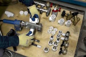
We calculate the material required for the manufacture of the collector. The easiest way to do this is in Excel spreadsheets. At the same time, in this program you can calculate the cost of materials required for the manufacture of the device. We purchase the necessary starting material and prepare tools for self-production.
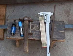
preparing tools
The starting materials for the main parts of the collector will be regular or square pipes. We make the necessary markings on them using calipers, a ruler and a core.
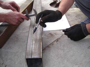
We make the necessary markings
Using a gas cutter, we make holes for the pipes.
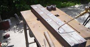
make holes for pipes
We insert the pipes (pipe sections with threads) into the seats.
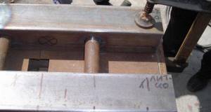
Insert the pipes
We fix the pipes by welding. First, rough it out, and then scald it around the entire perimeter.
We fix the pipes by welding
We also weld brackets to the body for wall mounting.
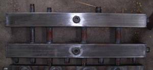
We weld the brackets to the body
We clean the welding areas from scale and rust.
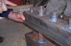
Cleaning the weld areas
We treat the entire structure with a degreasing compound and cover it with paint and varnish.
treated with a degreasing compound, coated with paint and varnish
The paint completely sets in two to three days and we have a self-made distribution manifold at our disposal. Now all that remains is to install it in place and connect all the incoming and outgoing circuits to it.
ready-made homemade distribution manifold
A system with a distribution manifold will work much more efficiently than a simple pile of heating pipes
In order to catch all the nuances of making a distribution manifold yourself and the scope of its application, we recommend that you watch the training video.