Heating system design
Elevator unit
The heating system of residential buildings begins with inlet valves that cut off the house from the route. It is along their flange closest to the external wall that the division of the areas of responsibility of housing and heating workers passes.
Further towards the house heating circuit are located:
- Hot water taps on the supply and return pipelines. The implementation may be different: each pipeline may have one or two tie-ins; in the second case, a flange with a retaining washer is mounted between the taps, creating a pressure difference to ensure continuous circulation. This is necessary so that the water in the DHW risers is hot around the clock, and the heated towel rails powered by hot heating remain hot.
Useful: in winter, when the supply temperature is below 90C, the DHW in this case is connected between the connections on the supply, and above - on the return. In summer, the circulation mode of the hot water supply system is from supply to return.
- The heating elevator itself is a key component that provides heating for a multi-story building. In it, hotter water from the supply, due to greater pressure, is supplied through a nozzle into the socket and, through a suction, draws part of the water from the return pipeline into a repeated circulation cycle through the heating circuit. It is the diameter of the nozzle that regulates the heating in an apartment building - it determines the real difference inside the heating system and the temperature of the mixture, and therefore the heating devices.
- House valves allow you to cut off the heating circuit. They are open in winter and closed in summer.
- After them, discharges - valves for draining or bypassing the system. In some cases, the heating system of a residential building is connected through a valve to the cold water supply system - solely to ensure that the radiators can be filled with cold water for the summer.
Spills and risers
The word “bottling” among professionals refers to both the direction of water circulation and the thick pipe through which water flows to the risers.
Typical heating of a 5-story building is made with bottom bottling. The supply and return pipes are routed along the outer contour of the house in the basement. Each pair of risers is a jumper between them. The risers are connected to each other upstairs - in an apartment on the top floor or in the attic.
- Jumpers placed in the attic are pure evil. It is almost impossible to ensure ideal thermal insulation of the attic and maintain a constant positive temperature in it. Any stop of heating means that after half an hour there is ice in the jumpers instead of water.
- An air vent is mounted at the top point of the jumper. In typical Soviet-built houses, it is a simple and extremely fail-safe design - the Mayevsky tap.
Bottom filling is associated with a problematic start of circulation after each discharge: the jumpers become air-filled, and for normal operation of all risers it is necessary to bleed air from each jumper. It can be problematic for locksmiths to get into all apartments, to put it mildly.
The heating system in a nine-story Soviet-built building is often somewhat different: the supply bottling is located in the attic. An expansion tank with an air valve is also mounted there; there is also one of a pair of valves that cuts off each riser.
After stopping and resetting the heating, problems with defrosting are extremely rare:
- When the bottling is laid at the correct slope and the vent is open, ALL water from the bottling and the top of the risers is discharged in a matter of seconds.
- Despite thermal insulation, bottling losses are large enough to warm up the attic even with minimal thermal insulation of the room.
- Finally, bottling is a pipe with a diameter of at least 40-50 millimeters with great thermal inertia, which, even with water without circulation, will not freeze in five minutes.
Top filling has a number of other features:
- The temperature of radiators decreases linearly from floor to floor, which is usually compensated by their large size. It is clear that below, already cooled coolant enters the heating devices; Therefore, heating of the first floor is usually carried out with the maximum number of radiator sections or the total area of convectors.
In addition: the temperature in the basement is usually lower than in apartments. Losses through the ceiling on the outer floors are usually much greater.
- Starting the heating is very simple: the system is filled; both house valves open; then the vent on the expansion tank opens for a short time - and ALL risers are involved in circulation.
- Removing a separate riser, on the other hand, is more difficult and involves a lot of movement. You first need to find and turn off the required riser in the attic, then find and shut off the second valve in the basement, and only then unscrew the plug or open the vent.
Heating devices
In Soviet-built houses, two types of heating devices are typical:
- Cast iron sectional heating radiators. The huge mass and heat transfer of 140-160 watts per section, not very aesthetic appearance and constant leaks of paronite gaskets between sections have recently made them unpopular in city apartments.
- In the 80-90s, central heating in an apartment building was often installed with steel convectors . The heating device is a turn or several turns of a solid DN20 pipe (3/4 inch) with pressed cross plates to increase heat transfer.
In the same 90s, they were massively replaced with radiators due to the very optimistic heat transfer calculated by the builders: due to lack of funding, the temperature schedule was rarely maintained, and it was very cold in the apartments.
Problem
The main problem that my relatives told me about was absolutely cold radiators in two adjacent rooms, while in other rooms the radiators became noticeably warmer with the start of the heating season.
- In rooms with warm radiators, the average daily temperature was +17C;
- In rooms with non-working heating +13C.
As they say, feel the difference...
For several days, calls from neighbors and relatives to the heating network ended in approximately the same way - nothing, because... the house is a cooperative one, and its maintenance is not their responsibility, except in emergency cases.
And for a cooperative of 60 apartments (4 entrances), where more than half of the residents are people of deep retirement age, it was expensive to maintain its permanent plumber out of pocket. The part-time specialist only made sure that there were no leaks during the startup of the system, and nothing more.
Searching of decisions
Having arrived at the place, the first thing I do is check the taps on the radiators and on the bypasses - everything is in the open position in both rooms. I open the Mayevsky taps on each radiator - a thin stream of water informs that there is pressure in the system and the radiator is not air-filled. But you need to find out whether there is any coolant in the system at all.
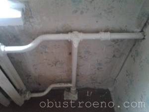
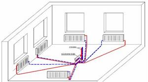
For this purpose I go to the basement of the house. From the elevator unit I determine the direction and find “my” supply and return pipes.
This is our highway.
Having reached the location of the apartments at our entrance, I see two pipes - supply and return. To the touch, both pipes differ quite noticeably, so it was not difficult to determine that the colder one was the return pipe.
In the foreground is the return line.
I use my hands again - both risers are cold, although literally a meter before this section the temperature was more than comfortable. The reason is the airing of the system on the upper fifth floor, which is why the coolant does not circulate.
I leave the basement and go to get acquainted with the neighbors on the upper floor, simultaneously inquiring from other residents about the presence of shut-off valves and their condition. As you would expect, they all have cast iron radiators installed 30 years ago.
The fifth floor is a bridge between rooms.
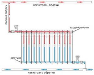
In Khrushchev-era houses there is no technical floor, so the coolant is supplied from below from the basement. To clarify the operation of the heating system, I propose to consider the diagram presented below.
Red arrows show the direction of movement from the supply, blue arrows indicate the return direction.
We return to the fifth floor apartment. In two rooms of a family of pensioners, cast iron radiators with 12 and 7 sections were installed. They were the ones who had to be ventilated.
The reason for the lack of heat is the accumulated air inside the radiator.
The only way available for this is using a nipple (a prototype of the Mayevsky tap) embedded in the radiator plug.
Upcoming job.
- Old galvanized bucket 12 liters;
- Pliers;
- Two flat blade screwdrivers;
- Several floor rags - splashes will be inevitable.
Here it is our simple tool.
I install a bucket under the radiator.
Since a lot of splashes are expected, I provide a place to work around the radiator - I remove the flower pots and move the furniture further away. Then I take a screwdriver and, carefully, so as not to lick the edges, unscrew the screw counterclockwise.
The effort has to be excessive.
- The old system did not work on the first try, I had to use pliers - with their help I turned the screwdriver until the screw came off the stuck place;
- The hiss of air marked the beginning of the air lock coming out. Within 3-4 minutes, the air left the radiator, after which cold water flowed in a thin stream;
- Having adjusted the screw so that the water poured into the bucket, I gave it time - in about half an hour, when the bucket was half filled, the temperature of the water changed from ice to warm, after which I screwed the screw back.
How not to remember the classic: “Oh, it’s getting warm...”
I did the same operation with a cast iron battery in another room. A few hours later, the apartments became noticeably warmer - the thermometer showed an increase of a couple of degrees. Of course, there is no need to talk about a complete solution to the problem of cold in the apartment, because... The coolant temperature is far from 75C, but it’s not yet a bitter winter outside.
I hope that my experience will be useful to some of you. If the symptoms are similar, negotiate with the neighbors on the top floor and ventilate the riser before the onset of winter. Good luck, comrades!
Temperature
There are a number of restrictions and regulations related to temperatures inside a living space.
- SNiP sets the following temperature standards: living rooms - 20C, corner rooms - 22C, kitchen - 18C, bathroom and combined toilet - 25C. It is better to focus on them if you are planning to switch to autonomous heating.
- In no utility service inside a residential building should the temperature exceed 95 degrees. For preschool educational institutions, the norm is even lower - 37 degrees. This is why in kindergarten groups you can see batteries of such a terrible size.
However: in the heating main at the same time there may be 140C at the supply.
How to cut heating
How to refuse heating in an apartment building?
Documentation
We will only partially touch on the documentary part. The problem is quite painful; permission to disconnect from the central heating center is given by organizations extremely reluctantly, and often it has to be obtained through the courts. It is quite possible that in your case it would be much more useful not to read a technical article, but to consult a lawyer knowledgeable in the Housing Code.
The main steps are:
- Let's find out if it is technically possible to turn it off. It is at this stage that most of the friction will occur: neither housing and communal services nor heat suppliers like to lose payers.
- Technical specifications for an autonomous heating system are being prepared. You need to calculate the approximate gas consumption (if you use it for heating) and show that you are able to provide a temperature regime in the apartment that is safe for the building’s structures.
- The fire inspection act is signed.
- If you plan to install a boiler with a closed burner and exhaust of combustion products to the facade of the building, you will need a permit signed by the Sanitary and Epidemiological Supervision Authority.
- A licensed installation organization is hired to draw up the project. You will need a full package of documents - from instructions for the boiler to a copy of the installers’ license.
- After installation is completed, a gas service representative is invited to connect the boiler and start it up for the first time.
- The last stage: you put the boiler on permanent maintenance and notify the gas supplier about the transition to individual heating.
Technical side
Refusal of heating in an apartment building is due to the fact that you need to dismantle all heating devices without disrupting the operation of the heating system. How it's done?
In houses with bottom filling, it is worth considering two cases separately:
- If you live on the top floor, you obtain the consent of the lower neighbors and move the jumper between the paired risers to their apartment. Thus, you completely isolate yourself from the CO. Of course, you will have to pay for welding work, installation of an air vent, and cosmetic repairs to the neighbors’ ceiling.
- On the middle floor, only heating appliances are dismantled, with welding and cutting off the hoses. A jumper of the same diameter as the rest of the pipe cuts into the riser. Then the riser along its entire length is carefully insulated.
Please note: refusal of central heating does not deprive you of the obligation to provide housing and communal services with access to the riser passing through your apartment upon first request.
In the case of top filling, events develop according to the second scenario. Even on the top floor, heating risers will pass through your apartment and connect to the bottling supply above (read also the article “Heating project and features of its design”).
What types of heating systems are there for an apartment building?
Depending on the installation of the heat generator or the location of the boiler room:
- An autonomous system in an apartment where the heating boiler is installed in a separate room or in the kitchen. The costs of purchasing a boiler, radiators and corresponding materials for piping are returned quickly, since such an autonomous system can be adjusted based on your own considerations regarding the temperature regime in the house. In addition, an individual pipeline does not lose heat, but on the contrary, it helps to heat the premises, since it is laid throughout the apartment or house. An individual boiler does not need to be adapted for the reconstruction of central heating - once drawn up and implemented, the heating scheme will work for a lifetime. And finally, the already working circuit can be supplemented with parallel or sequentially connected circuits, for example, a “warm floor”;
- An individual heating option that is designed to serve an entire apartment building or an entire residential complex is a mini-boiler room. Examples include old boiler houses serving a neighborhood, or new complexes for one or more houses using different energy sources - from gas and electricity to solar panels and thermal springs;
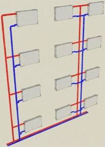
Single-pipe heating system diagram
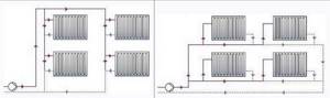
Single-pipe heating system: vertical and horizontal distribution.
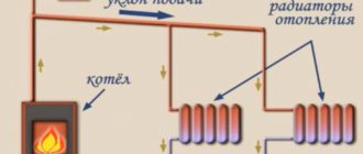
In a single-pipe heating system, the supply of hot coolant (supply) to the radiator and the removal of cooled coolant (return) are carried out through one pipe. All devices relative to the direction of movement of the coolant are connected to each other in series. Therefore, the temperature of the coolant at the inlet of each subsequent radiator along the riser is significantly reduced after heat is removed from the previous radiator. Accordingly, the heat transfer of radiators decreases with distance from the first device.
Design features of the heating circuit
Modern buildings often use additional elements, such as collectors, heat meters for batteries and other equipment. In recent years, almost every heating system in high-rise buildings has been equipped with automation to minimize human intervention in the operation of the structure (read: “Weather-dependent automation of heating systems - about automation and controllers for boilers using examples”). All the described details allow you to achieve better performance, increase efficiency and make it possible to more evenly distribute thermal energy throughout all apartments.
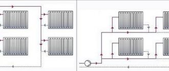
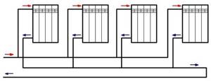
Two-pipe heating system diagram
In two-pipe schemes, the supply of hot coolant to the radiator and the removal of cooled coolant from the radiator are carried out through two different pipelines of the heating systems.
There are several options for two-pipe schemes: classic or standard, associated, fan or beam.
Two-pipe classic wiring
Classic two-pipe heating system wiring diagram.
In the classical scheme, the direction of movement of the coolant in the supply pipeline is opposite to the movement in the return pipeline. This scheme is most common in modern heating systems, both in multi-storey buildings and in private individual ones. The two-pipe circuit allows you to evenly distribute the coolant between radiators without loss of temperature and effectively regulate heat transfer in each room, including automatically through the use of thermostatic valves with installed thermal heads.
Such a device has a two-pipe heating system in a multi-story building.
Associated scheme or “Tichelman loop”
Associated heating wiring diagram.
The associated scheme is a variation of the classical scheme with the difference that the direction of movement of the coolant in the supply and return is the same. This scheme is used in heating systems with long and remote branches. Using a passing circuit allows you to reduce the hydraulic resistance of the branch and distribute the coolant evenly across all radiators.
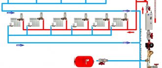
Fan (radial)
A fan or radial scheme is used in multi-storey construction for apartment heating with the possibility of installing a heat meter (heat meter) in each apartment and in private housing construction in systems with floor-to-floor piping. With a fan-shaped scheme in a multi-storey building, a collector is installed on each floor with exits to all apartments of a separate pipeline and an installed heat meter. This allows each apartment owner to account for and pay only for the heat they consume.
Fan or radiant heating system.
In a private house, a fan diagram is used for floor-to-floor distribution of pipelines and for radial connection of each radiator to a common collector, i.e., each radiator has a separate supply and return pipe from the collector. This connection method allows you to distribute the coolant as evenly as possible across the radiators and reduce hydraulic losses of all elements of the heating system.
Note! When distributing pipelines in a fan pattern within one floor, installation is carried out in solid (without breaks or branches) sections of pipes. When using polymer multilayer or copper pipes, all pipelines can be cast into a concrete screed, thereby reducing the likelihood of rupture or leakage at the junction of network elements.
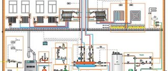
Features of heat supply of multi-storey buildings
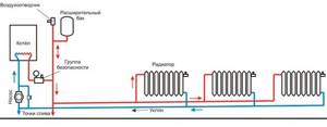
Autonomous heating of a multi-storey building must perform one function - timely delivery of coolant to each consumer while maintaining its technical qualities (temperature and pressure). To do this, the building must have a single distribution unit with the ability to regulate. In autonomous systems it is combined with water heating devices - boilers.
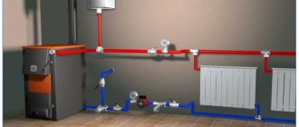
The characteristic features of the heating system of a multi-storey building lie in its organization. It must consist of the following mandatory components:
- Distribution unit. With its help, hot water is supplied through the mains;
- Pipelines. They are designed to transport coolant to individual rooms and areas of the house. Depending on the method of organization, there is a single-pipe or two-pipe heating system for a multi-story building;
- Control and regulating equipment. Its function is to change the characteristics of the coolant depending on external and internal factors, as well as its qualitative and quantitative accounting.
In practice, the heating scheme of a residential multi-storey building consists of several documents, which, in addition to drawings, include a calculation part. It is compiled by special design bureaus and must comply with current regulatory requirements.
The heating system is an integral part of a multi-storey building. Its quality is checked upon delivery of the facility or during scheduled inspections. Responsibility for this lies with the management company.
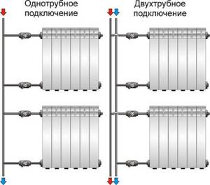
Types of radiator connections
The main methods of connecting heating system devices are several types:
- Lateral (standard) connection;
- Diagonal connection;
- Bottom (saddle) connection.
Side connection
Lateral radiator connection.
Connection from the end of the device - supply and return are located on one side of the radiator. This is the most common and effective connection method; it allows you to remove the maximum amount of heat and use the entire heat transfer of the radiator. As a rule, the supply is at the top and the return is at the bottom. When using a special headset, it is possible to connect from bottom to bottom, this allows you to hide the pipelines as much as possible, but reduces the heat transfer of the radiator by 20 - 30%.
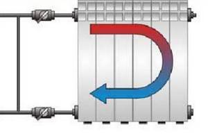
Diagonal connection
Diagonal radiator connection.
Connection diagonally to the radiator - the supply is on one side of the device from the top, the return is on the other side from the bottom. This type of connection is used in cases where the length of a sectional radiator exceeds 12 sections, and a panel radiator is 1200 mm. When installing long radiators with side connections, there is uneven heating of the radiator surface in the part furthest from the pipelines. To ensure that the radiator heats up evenly, a diagonal connection is used.
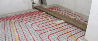
Manifold systems and underfloor heating connection
Combining different types of circuits is very useful; it helps to “tailor” the heating system to different technical conditions. The technical implementation of such projects is simplified with the use of distribution manifolds.
The first type is a simple two-row comb with shut-off valves, which has a pair of outlets for each wing. Each of them can have a different number of radiators installed with an arbitrary connection diagram, but usually the total number of sections does not exceed ten.
The second type of collectors has transparent flasks with floats for visually adjusting the flow rate. Heated floor pipes and wings of different lengths are connected to such units; instead of ball valves, a valve regulator is installed on each line.
Manifolds for heated floors can be equipped with an additional recirculation pump and a general thermostat. This is very typical for multi-storey buildings, for example, when combining underfloor heating with radiators on different floors. The base coolant temperature is 60-70 degrees, which is very high for a heated floor. Therefore, the pump mixes in some of the return water, reducing the floor heating to 35-40 °C.
The construction of decoupling on collectors is also convenient for maintenance. You do not have to stop the entire heating system in the event of a breakdown, since each section can be switched off and drained selectively.