How it works
The part of the cylinder that was initially cut off will be used as a waste container.
Do not forget that under no circumstances should you use kerosene or gasoline instead of oil - this can lead to an explosion. If desired, you can use the finished structure not only to heat the room, but also as a stove for cooking food. It is enough to weld a steel rectangle to the lid. Fill two-thirds of the container with oil; for ignition, you can add a little kerosene or gasoline; a rag soaked in one of these liquids will do. After 3-5 minutes, all the gasoline will burn out and the exhaust will begin to work.
After finishing use, you should clean (at least partially) the cylinder itself - just tap the lid on top of the structure thoroughly so that all the carbon deposits fall off.
What is mining
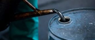
Waste oils are engine oils that have lost their beneficial properties for a car. During the replacement process, used fluids are sent to waste, so you can purchase fuel for the furnace at a low price and in large quantities. For the convenience of obtaining oil, enter into an agreement with the nearest auto repair shop.
The flow rate is 2 liters per hour. Depending on the size of the room and method of operation, the figure may vary. An oil-fired stove is suitable not only as a heater for a work area, but also heats water for various needs.
How to use the oven
To decorate the stove and make it more attractive in appearance, you can make special paint. The proportions of the ingredients are as follows: for 500 g of liquid glass you will need 200 g of aluminum powder and 20 g of chalk. You get a lot of paint, so you can proportionally reduce the amount of ingredients.
After vigorous shaking, all components are mixed, and the paint can be safely applied to the stove with a regular brush.
Please pay attention to a number of safety rules when operating the oven:
The unit should be installed away from drafts; Highly flammable objects and substances should not be left near the stove; there should be about 50 cm of clearance on all sides of the stove; It is important to avoid getting water into the oil container, as this will cause boiling fuel to splash through the burner; the chimney must be tightly connected to the unit; The fuel for such a furnace can only be technical oil.
The oven warms up to operating temperatures within 5 minutes. The waste is poured into the fuel tank to 2/3 of its capacity, and about 20-30 g of solvent or gasoline is poured on top. Light the wick on the wire and use it to ignite gasoline through the oil filling hole. This will heat up the oil faster so that evaporation can begin. When the vapors ignite in the burner, you can see a stable flame, fueled by the incoming oxygen. Using a blower, you can slightly regulate the intensity of combustion.
Please note that a burning stove should not be left unattended.
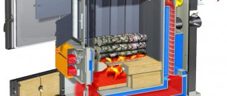
How Gecko boilers function
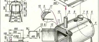
To become familiar with the general operating principle, you need to familiarize yourself with the stages of converting fuel into thermal energy.
- The fuel line (9) carries the waste oil to the evaporator (11).
- Under the influence of temperature, the above-described transformation into gas occurs.
- So it is lighter than air - the vapors rise through the vortex device (14).
- Passing through the holes in this element, they ignite in the combustion chamber.
- The air blower enriches the mixture with oxygen, which increases thermal output.
- The transfer of energy and coolant (water, antifreeze) occurs through the walls of the heat exchanger. They are in the combustion chamber.
To remove carbon monoxide, the design includes a gas duct. It is also intended to create draft that ensures the circulation of air flows inside the combustion chamber.
Making such a structure with your own hands is not problematic. The main thing is to select the right material for production and act in accordance with the developed technological scheme, taking into account the specifics of the drawing.
Bottom of the firebox chamber and burner
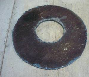
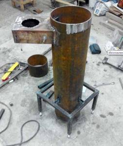
I cut out the bottom from steel. I decided to make the burner 20 cm long - that would be enough.
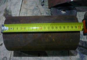
This will be the burner
I made many holes around the circumference so that air could easily get to the fuel. Once all the holes were done, I sanded down the inside of the burner. You should definitely do this too, because... soot will begin to actively accumulate on the protrusions and other defects.
First, I welded the burner into the bottom of the upper chamber, and then installed them in their proper place. You can safely lay wood on such a stove shelf. Relevant for cases when it is not possible to replenish mining reserves.
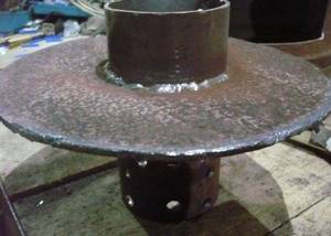
First I welded the burner into the bottom of the upper chamber
Drawings and diagrams
In order not to create drawings and diagrams yourself, you can always use ready-made ones. Below are the best and proven options:
How to clean the oven?
First cleaning
As work progresses, soot will accumulate in the burner, flue pipe and oven tray. Naturally, the stove can be cleaned only after it has cooled down.
When cleaning, I usually follow the following sequence:
- I take a couple of handfuls of clean sand or small gravel and throw them one by one into the exit of the smoke exhaust pipe from the street side;
- I remove sand or gravel with soot from the chimney through the upper chamber;
- Using a rod, I brush away the fumes from the walls of the stove burner into the lower pan;
- I take out the tray itself and empty out the waste.
I hope my experience will be useful to you, and you can assemble a stove using waste oil as easily as I did.
Good luck!
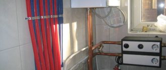
Heat transfer systems
One of the most efficient are exhaust boilers with a water circuit and a forced air blowing system. For the heat exchanger coil, ordinary copper pipes with a diameter of 10-16 mm are used. The most efficient exhaust boilers are water-based; they are capable of maintaining temperatures up to 200 Co – 250 Co . It is advisable to use them as a backup source of heat supply in parallel with the general heating system of the cottage.
Heat exchange systems - Photo 10
Bottom of the firebox chamber and burner
Then I made the bottom for the top compartment of the stove. For this I used a sheet of steel 4 mm thick.
I cut the bottom out of steel. I’m trying on the bottom. Everything is cut out neatly and fits together with almost no gaps. The bottom is in place.
I decided to make the burner 20 cm long - that would be enough.
This will be a burner. Drill holes. Grind.
I made many holes around the circumference so that air could easily get to the fuel. Once all the holes were done, I sanded down the inside of the burner. You should definitely do this too, because... soot will begin to actively accumulate on the protrusions and other defects.
First, I welded the burner into the bottom of the upper chamber, and then installed them in their proper place. You can safely lay wood on such a stove shelf. Relevant for cases when it is not possible to replenish mining reserves.
First, I welded the burner into the bottom of the upper chamber. Installed the burner
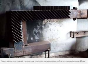
Recommendations for increasing the efficiency of a homemade stove
How to increase the efficiency of bubafoni? What problem is preventing this heat generator from working to its full potential? One of the problems is that the stove body heats up unevenly. Because of this, we get poor heat exchange in the room. Is it possible to solve this problem? Of course you can. To solve this problem, let's take a sheet of corrugated metal profile. We wrap it around the stove, obtaining a protective “shirt” and spot-weld the profile sheet to the cylinder.
You can find another solution besides welding. It's up to you to decide. By implementing this solution into a finished design, we will obtain a long-burning furnace device that forms rising air currents. Cold air will rise from the bottom of the ribs. After passing along the body of the cylinder, the air will heat up and become hot at the outlet. In addition to this modification, you can do the following.
Cover the entire structure with bricks. This will allow heat to accumulate from the generator, releasing it evenly over the entire area of the building for quite a long time. In addition to the profile sheet, you can use pipe scraps. Profile or regular round pipes are suitable. They are welded around the cylinder body, resulting in an effective design for generating heat with uniform heating.
Making a pyrolysis furnace for mining
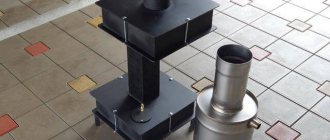
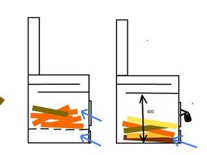
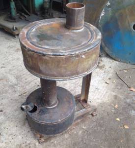
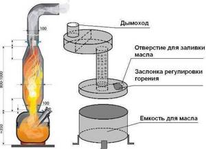
Now you know how to assemble a stove from a gas cylinder with your own hands. The unit running on exhaust or any oil will delight you with a lot of heat. For example, the exhaust furnace diagram presented above is designed to heat a room with an area of 70-80 square meters. m. Let's now look at the scheme for creating a pyrolysis unit - that is, a small potbelly stove.
Assembly diagram of a pyrolysis furnace operating on waste.
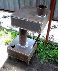
This oven will consist of three main parts:
- Oil container with lid and flap;
- Combustion/pyrolysis chamber;
- Afterburner chamber.
It all culminates with a chimney. Its recommended length is at least three meters, but chimneys with a height of 4-5 meters work best.
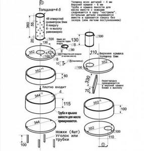
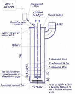
The oil container is made from a piece of pipe with a diameter of 344 mm, its height is 100 mm. We weld a sheet metal lid on the bottom. Our top cover is removable, it is made from a pipe with a diameter of 352 mm - sides with a height of 600 are welded to it. In the cover we make a central hole for the combustion chamber with a diameter of 100 mm. We make a hole nearby with a diameter of 60 mm - it will serve as a blower. This hole is closed with a simple rotating lid.
By adjusting the clearance of the blower, we can regulate the intensity of combustion, which will affect the air temperature in the room. If you completely close the vent while the stove is running, it may go out.
We make an afterburning chamber - we use a pipe with a diameter of 352 mm and a height of 100 mm. In the lower part we make a hole with a diameter of 100 mm into which the combustion chamber pipe is inserted. In the top cover we make a hole with a diameter of 100 mm for the chimney. Inside, closer to the chimney opening, we weld a small partition 330 mm wide and 70 mm high. Our do-it-yourself oven is almost ready.
It remains to modify the combustion chamber. Everything is simple here - take a drill and a 9 mm drill bit, drill 48 holes (6 rows of 8 holes each). With a total combustion chamber pipe height of 360 mm, the holes should be located in an area 20 mm from the bottom and 50 mm from the top.
After completing all the work, check the tightness of all welds - this will allow you to count on maximum efficiency of the stove.
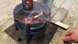
Check the performance of the resulting unit outside. This will protect you from possible fire and other accidents.
We start testing the furnace - we install it outside, pour the waste into an oil container, and add kerosene on top. Carefully set it on fire, leaving the ash pan open. After some time, the stove will return to operating mode - you can adjust the burning intensity using the blower. After this, the stove is moved indoors (it must be ventilated).
In order for heating to be as efficient as possible, install the furnace in a corner, and line the side walls with galvanized iron so that all the heat is reflected into the room.
Advantages and disadvantages of “working off”
This method is often used in non-residential premises such as garages, workshops, warehouses, etc. It all works quite simply - first the waste is heated, after which oil vapors are formed, which also burn, and much more intensely than the liquid fuel itself. As a result, we have a fairly efficient gas cylinder stove that is capable of heating a small room for a very small amount.
This method of heating a room is extremely popular in car repair shops - they always have free oil on hand, which is drained from old cars. In this case, the heat is generally free, plus, there is no need to look for how to dispose of old oil. The only point is that before use it needs to be cleaned so that there are no all kinds of impurities .
After reading the list below, you can finally decide whether it is worth assembling a stove from a cylinder with your own hands, since there are many nuances associated with both the unit and the type of fuel used in it. Pros:
The cost of a furnace operating during mining is minimal. If you don’t want to buy it, you can make it yourself from the same gas cylinder or sheet metal. There are plenty of drawings and videos on the Internet; even a person with minimal skills can repeat the entire process.
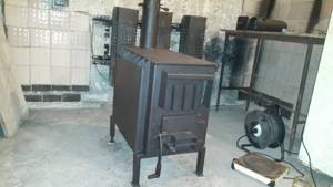
Factory furnaces, their characteristics and features
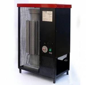
The photo shows the factory furnace Teplamos NT-612, running on waste oil.
Before we tell you how to make a furnace for working with your own hands, we will look at several models of factory-assembled furnaces. A typical example is the Teplamos NT-612 oven. This is a typical drip fanless heater, intended for use in garages, workshops, hangars and other non-residential and technical premises. The power of the device varies from 5 to 15 kW, fuel consumption - from 0.5 to 1.5 l/hour.
Teplamos NT-612 is a closed type oven. It contains a chimney and a pipe for air supply. Combustion of fuel occurs in the inner chamber. In order for the stove to reach operating mode, it must be heated with a small amount of diesel fuel poured into a special bowl. After the fuel burns, we get a stove ready for refueling and further work - we open the waste supply and set it on fire.
The design of this unit has a built-in tank that can hold up to 8 liters of fuel.
A mini-furnace of the “potbelly stove” type is as simple as a matchbox. It is made of sheet iron and is characterized by versatility - it heats non-residential premises and allows you to cook food (small pots, pans and kettles are placed on the surface of the afterburning chamber). The power of such units varies widely. The equipment operates on the basis of pyrolysis.
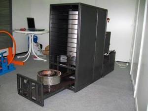
Zhar MS-25 can operate on both waste oil and diesel fuel.
Let's consider a more solid stove - this is the heat generator Zhar MS-25. The unit can operate on both waste oil and diesel fuel. For its operation, electricity is required to power the built-in fan. The thermal power of the device is 25-50 kW, which allows it to heat an area of up to 500 square meters. m. In this case, the maximum flow rate is up to 4.5 l/hour. The stove is quite large, it weighs 130 kg and requires a good chimney. The temperature of the air entering the heated rooms is +50-70 degrees.
Fuel requirements
When they say that any waste can be burned in a stove, this is only partly true. Motor, transmission or industrial oil is suitable as fuel, but without impurities, metal shavings and water. When heated, the water boils and splashes out, causing a sudden ignition.
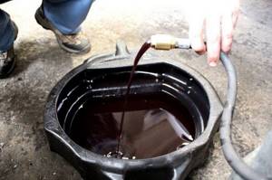
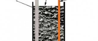
To remove unnecessary suspended matter, it is recommended to filter the waste and settle it in a barrel. Water falls down, volatile substances evaporate. The container must be open, and ventilation must be provided at the place of its installation.
There is a fairly effective way to convert waste of not very high quality into a fuel emulsion. This is whipping butter in a closed container at high speeds. This creates a homogeneous mixture that burns more evenly, without splashing.
Operating principle of a waste oil furnace
The prototype for oil furnaces operating on waste oil is kerogas, which was previously used in villages and dachas. It used kerosene as fuel, the vapors of which were burned in a separate chamber. To save on fuel, a waste oil burning option was developed. It can be purchased for free or at a reasonable cost at any service station.
Components of a waste oil stove
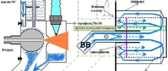
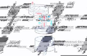
Creating a homemade stove during mining is not a difficult process. The main task is to properly organize the system for a productive oil combustion process. To ensure complete combustion of vapors, heavy components must first be split into light ones, which is carried out as a result of pyrolysis. The oil must be properly heated for efficient evaporation.
The operating principle of an oil furnace during mining is as follows. First of all, the mining is ignited in the lower chamber of the apparatus. The combustion intensity is regulated using a throttle valve in the device body, through which air enters the chamber. Oil vapor mixed with oxygen rises upward through a vertical pipe. The pipe is connected to the upper tank, which is the afterburner chamber.
The mixture is mixed under the influence of the Coriolis force (force of inertia). The intensity of the process is achieved by choosing the correct diameter and length of the combustion chamber. To ensure complete combustion, air must flow through the damper in sufficient quantity. To do this, it is additionally sucked through holes made in a vertical perforated pipe connecting the tanks.
The combustion intensity is regulated using a throttle valve in the device body
The gas flow is directed to the final combustion chamber, in which the upper part is expanded. During its manufacture, a horizontal separation is made between the chimney inlet and the combustion chamber outlet, which is necessary to ensure a temperature jump between the nitrogen oxide and oxygen afterburning zones. At temperatures below 600 °C, nitrogen oxides are more active than oxygen. As they decompose, they oxidize fuel particles. With increasing temperature, oxygen acts as the main oxidizing agent. Harmful substances are released into the atmosphere through the chimney.
We make a heat generator from a cylinder
First of all, prepare the gas cylinders for welding - remove the spherical parts (don't forget to fill them with water first!) and cut one to size so that together they form a body of the required height (1 m).
Prepare the remaining materials, taking into account the following recommendations:
- It is better to make the combustion chamber and flame bowl from stainless steel with a thickness of 1.5-3 mm (for example, grade 12X18H12T);
- if you couldn’t find stainless steel, use black steel grade St3 - St20 from 4 mm thick;
- Also select a stainless steel waste oil supply tube;
- wall thickness of flame tubes – at least 3.5 mm;
- to seal the top cover, select a 40 x 4 mm steel strip (rim) and an asbestos cord;
- prepare 3 mm sheet metal for the manufacture of an inspection hatch;
- For the heat exchanger, use steel with a thickness of at least 4 mm.
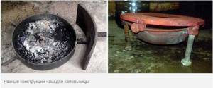
Options for manufacturing bowls installed on the bottom of the heating unit
Advice. As a supercharger, craftsmen usually use the “snail” of the VAZ 2108 cabin heater, but this is not a panacea. Take any similar fan - its performance will still have to be adjusted in order to increase or decrease the boiler power.
The manufacturing process of a two-pass boiler during testing looks like this:
- Cut the Ø32 mm flame tubes to size and weld the heat exchanger using one cylinder as the outer casing and a Ø150 mm tube as the walls of the combustion chamber.
- Attach the water heating system supply pipes to the heat exchanger.
- In the second cylinder, cut holes for the inspection hatch and chimney pipe. Weld a Ø114 mm fitting and make a neck with a cover from sheet steel.
- Weld both tanks into one body. Make a shell of iron strip on top - it will serve as a seal for the lid. Fill the gap between the edges with asbestos cord.
- Make an afterburner in accordance with the drawing. Make holes in the hemispherical cover (formerly the end of the cylinder) for the viewing window and installation of the afterburner (in the center).
- Equip the lid with handles and a shutter on the window. The afterburner pipe can be tightly welded to it or screwed with bolts sealed with asbestos cord.
At the bottom end, the perforated pipe is closed with a plug, where 4 holes are made - one in the middle, the remaining three - radially. An oil pipeline tube is inserted into the central hole and scalded. The last step is to make a flame bowl of the boiler where the waste oil will burn.
The lower (end) part of the afterburner with holes
Recommendation. If you want to make an exhaust boiler installation with a water circuit that provides hot water supply, do not rush to push the coil inside the heat exchanger. There is a simpler solution: weld 2 additional pipes to the water jacket and connect them to the indirect heating tank through a circulation pump. The second option is to install a samovar-type heat exchanger on the chimney.
Upon completion of assembly, weld an elbow with a flange to the afterburner pipe and install the “snail”. To prevent the outer metal wall of the water jacket from wasting heat in vain and heating the boiler room, insulate the body from non-flammable basalt wool. The simplest way is to wrap the insulation with twine and then wrap it in thin sheet painted metal.
The outer casing of the heat generator can be made rectangular
The manufacturing process of an oil-fuel boiler is demonstrated more clearly in the following video:
How to weld a simple stove
If we talk about a simple heater, then a detailed drawing gives a complete idea of what needs to be done to assemble it yourself. To do this you will need rolled metal, a pipe, a sheet of iron. Tools – drill, cutter, welding machine. It is a little more difficult to produce a bent afterburner, which is necessary for the furnace to operate with greater productivity. The standard angle is 90 degrees. More is possible, but no sharper. The achieved effect is simple - retention of hot exhaust air.
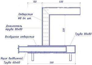
Then the heat is released in greater quantities into the room, rather than being “thrown out” to the street. Another upgrade is to make an iron drawer. Oil is poured into it. With this design, the stove is easier to maintain. The drawing contains all the necessary dimensions. Before assembling a homemade oil stove, it is necessary to select the correct diameter of the firebox and body.
Here everything depends on the volume of the room that needs to be heated. If it is a garage of 3 by 6 meters, take a profile of 80x80x4 mm. The fuel box is made of metal 60x60x4. It is more difficult to work with round rolled metal.
The step-by-step instructions look like this:
- Cut the metal according to the drawings to make a casing, drawer, afterburner. If the latter has a bend, the tube is cut at an angle of 45 degrees.
- For a profile of a smaller standard size, one wall is cut out with a grinder. Plugs are welded to the sides. The result is an open container to which you need to attach a handle.
- The structure is welded. It is necessary to drill an air hole at the top of the fuel chamber. The pipe is perforated. At this point the work is completed.
It should be taken into account that you need to calculate the number and diameter of holes in the afterburner. If you use a profile of 80 by 80 mm, then the cross-sectional area will be equal to 6400 square millimeters. This value is divided in two
Pay attention to the markings of the drill used. If it is 8 mm, then the hole area will be 50 sq. mm
Now 3200 must be divided by 50. The result is that 64 holes will be required to work effectively. However, as a result of customization, their number can be increased.
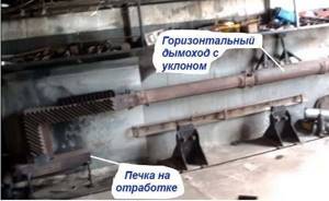
It is important that the chimney is of sufficient length. The elevation of the chimney outlet must be at least 5 meters
Then the operation of the stove during testing will ensure the highest possible efficiency even without supercharging. Otherwise, the pipe will have to be extended to this mark. But you can further increase productivity if you organize an inclined chimney running along the wall. The heated metal will release heat into the room. Only in this case is it important to follow fire safety rules. There should be no wooden shelves above the pipe, and no wallpaper on the walls. Even better is to cover the wall with a metal sheet.
Making a drip heater
Professionals who have assembled more than one “dripper” use old propane cylinders with a diameter of 200 mm. Oxygen ones are also suitable, since their cross section is 220 mm. the latter benefit due to thick walls. They serve for a long time, do not burn out, and accumulate heat. Pipe C-10 is also suitable if it has a wall thickness of 5 mm. An excellent option for a durable housing is pipes made of heat-resistant stainless steel alloys, alloyed chromium, molybdenum or nickel (for example, 15X1MF or 12X18H12T) with a wall no more than 3 mm. However, it is not advisable to specifically purchase this raw material due to its high cost.
Technologically, the manufacturing process is as follows:
- A flame bowl is made using a piece of pipe or ready-made steel containers. This one is pulled out through a rubber hatch, so it is not made too big.
- The openings necessary for connecting the chimney pipe and the cleaning service hatch are cut out in the body. The latter is framed and closed with a door. Bolts can be used for fastening.
- An afterburner is being made. All holes are not made at once. Usually the bottom 2-3 rows are drilled, and the rest are drilled during the setup process. If you do everything at once and there are too many of them, you will have to make a new one.
- Weld the cover with the air duct and flange. The latter is necessary for installing the fan. The fuel supply device is connected. Photo and video instructions will help here.
Now assemble all the components and connect the electrical wiring. The structure will be more stable if you make a metal frame. A heavy metal profile is suitable for this.
Dispenser
The specificity of working boilers with waste oil is to create a device for supplying fuel. It is recommended to develop a simple and reliable circuit in which the oil will flow into the combustion chamber in the required volume.
The designers of the Gecko boilers followed the path of “least resistance”. The principle of communicating vessels was used. The dispenser is installed separately from the boiler and connected to it using a fuel line.
(Dispenser diagram)
The fuel supply is adjusted by setting the float position. It opens (closes) the supply tap. In this way you can reduce or increase the heating power.
When calculating the model design of a waste oil boiler, it is necessary to take into account the following nuances:
- Volume dispenser;
- Replenishment mechanism;
- Material for making the float. It should not be destroyed by fuel.
Having a general understanding of the operating principle of boilers of this type, you can begin to manufacture the structure yourself.