A temperature sensor assembled with your own hands can bring undoubted benefits both in the home and in the garden. The ambient temperature controller will promptly turn on or turn off the fan, heater, boiler, heated floors and many other appliances in the house, heat or ventilate greenhouses. If you have minimal experience with tools, making a temperature sensor with your own hands will not be difficult.
DIY thermostat: diagram
About the design of the thermostat, we can say that it is not particularly complicated, it is for this reason that most radio amateurs begin their training with this device, and also hone their skills and craftsmanship on it. You can find a very large number of device circuits, but the most common is a circuit using a so-called comparator.
This element has several inputs and outputs:
- One input responds by supplying a reference voltage that corresponds to the required temperature;
- The second receives voltage from the temperature sensor.
The comparator itself receives all incoming readings and compares them. If it generates a signal at the output, it will turn on the relay, which will supply current to the heating or refrigerating unit.
Thermal relay circuit
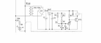
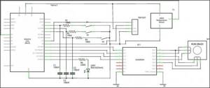
There are a great variety of thermostat circuits described in amateur radio literature, therefore, without any pretense of originality, I present the circuit that I personally assembled for my car. As I said above, the scheme is almost standard. It consists of a comparator on an operational amplifier and two circuits that set the voltage at its inputs.
The voltage at the non-inverting input is set by trimming resistor R2, and the voltage at the inverting input is taken from the engine temperature sensor, which is a thermistor that, together with other parts of the car circuit, forms a temperature-dependent voltage divider.
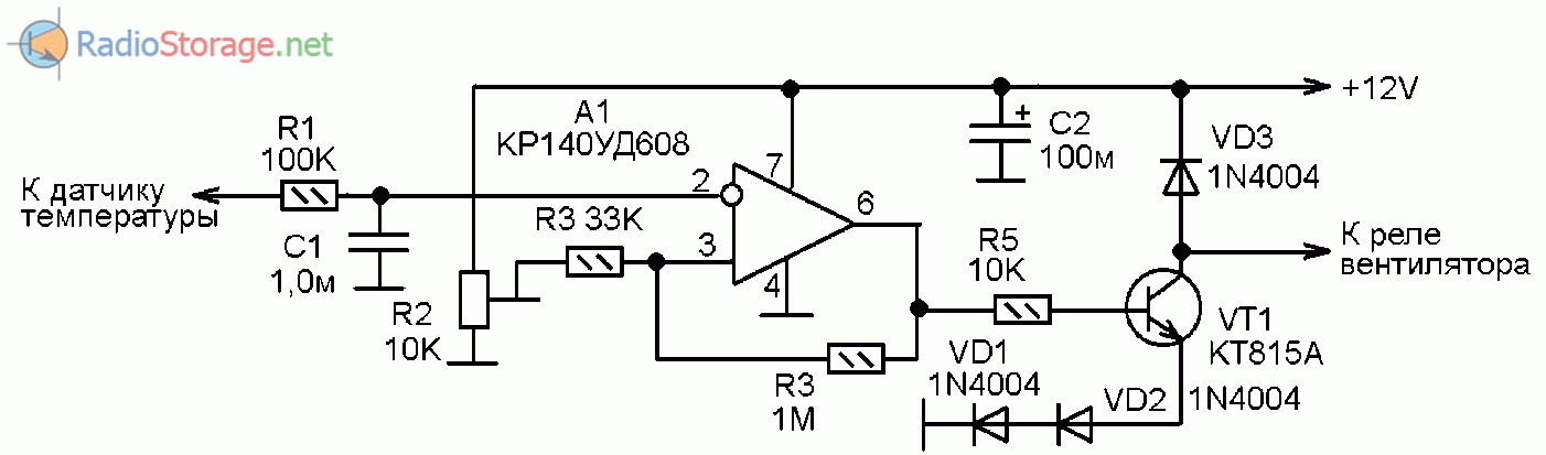
Rice. 1. Schematic diagram of a thermal relay for turning on engine cooling in a car.
At the output of the circuit there is a switch on transistor VT1; its collector is connected to the winding of the relay that controls the electric fan. And power is supplied to the circuit from the output of the car’s ignition switch, so that power is supplied to the circuit only when the ignition is on. This is necessary because when the ignition is turned off, voltage is usually not supplied to the temperature sensor circuit; accordingly, the voltage at the temperature sensor drops to zero, regardless of the temperature value.
Principle of operation
The idea of creating a temperature sensor is that it uses an electrically conductive element, which, under the influence of fluctuations in ambient temperature, changes its resistance. Such an element is a thermistor.
The operating principle of variable resistance is that when heated, the resistance decreases and the current flowing through it changes its characteristic. This process is reflected in the operation of the application circuit, which turns on or off the corresponding devices.
The essence of the device
A thermometer, a colloquial analogue - a thermometer, is designed to measure the ambient temperature. The first device was invented in 1714 by the German physicist D. G. Fahrenheit. He based his design on a transparent sealed flask containing alcohol. Afterwards, the scientist used mercury as a liquid. But the analog meter scale, which still exists today, was developed only 30 years later by the Swedish astronomer and meteorologist Anders Celsius. He suggested taking the temperature of melting ice and boiling water as starting points.
An interesting fact is that initially the number 100 was the melting temperature of ice, and the boiling point was taken as zero. Subsequently, the scale was “turned over.” According to some opinions, this was done by Celsius himself, according to others - by his compatriots, the botanist Linnaeus and the astronomer Stremer.
Soon the production of mercury meters was widely established on an industrial scale. Over time, mercury, due to its toxicity, was replaced by alcohol , and then a new type of device was proposed - digital. Today, perhaps, a thermometer has become an integral attribute of any home. On the advice of the World Health Organization, the Minamata Convention was adopted, aimed at gradually eliminating mercury thermometers from use. According to it, in 2022 the use of mercury in meters will be completely phased out.
Therefore, due to its excellent characteristics, a thermometer with a digital circuit has practically no competitors. Alcohol devices offered for sale are inferior to them in terms of accuracy and ease of data perception.
Electronic models can be located anywhere, because in the controlled room it is necessary to place only a small sensor connected to the device. This type is used in many industrial processes, for example, construction, agriculture, and energy. They help control:
- air temperature in industrial and residential buildings;
- checking heating of bulk products;
- state of viscous materials.
Principle of operation
Before you start making an electronic thermometer, you should understand the principle of its operation and decide what components the structure will consist of. Industrially produced electronic thermometers vary in size and purpose. But they are all built on the same operating principle.
The conductivity of the material varies depending on the ambient temperature. Based on this, an electronic thermometer circuit is designed. So, most often a thermocouple is used in the design. This is an electronic device made of two metals welded together. On the surface of each of them there is a contact pad connected to the measuring circuit. When the contacts are heated or cooled, a thermoelectromotive force arises, the appearance and change of which is recorded by the electronics board.
New generation devices use a silicon diode instead of a temperature-sensitive element. A semiconductor radio element whose current-voltage characteristics depend on temperature exposure. In other words, with direct connection (direction of current from anode to cathode), the value of the voltage drop across the junction changes depending on the heating of the semiconductor.
The processed data is displayed on the display, from which it is visually captured by the user. Digital thermometers allow you to measure temperature changes ranging from -50°C to 100°C.
In total, five blocks can be distinguished in the design of a simple thermometer:
- A sensor is a device that changes its parameters depending on the temperature affecting it.
- Test leads - used to extend the sensor and place it in various places that require temperature control. Most often these are conductors with a small cross-section in diameter, not even necessarily shielded.
- Electronics board - contains an analyzer block that records changes in the signal coming from the sensor and then transmits it to the screen.
- Display - a monochrome or color screen designed to display data on the measured temperature.
- Power supply - assembled on integrated circuits typical for radio electronics. Used to stabilize and convert power supplied to all board nodes.
Manufacturing Features
For a person who is interested in amateur radio, making an electronic thermometer with his own hands using a circuit diagram will not present any difficulties, but at the same time, an ordinary consumer will need to have at least soldering skills. Today there are quite a few different schemes, differing both in the complexity of their repetition and in the scarcity of radio components.
When choosing a circuit, take into account the characteristics that it can provide to a future measuring device. First of all, this is the range of measured temperatures, and secondly, the error. Structurally, you can assemble a wired and wireless model. When assembling the second type, a radio module is used, which significantly increases the cost of the product.
Due to the use of sensitive specialized microcircuits, it is unlikely that it will be possible to assemble the circuit by surface mounting. Therefore, a printed circuit board is pre-fabricated. It is better to make it from one-sided foil fiberglass using the “laser-ironing technology” method.
The essence of the method is that, using, for example, Sprint Layout, a printed circuit diagram of the device is drawn and printed in a mirror image at a scale of 1:1 on a laser printer. Then, attaching the printed design with the image down to the foil layer, iron the drawing with a heated iron. Due to the characteristics of the toner, the image of the lines will be transferred to the fiberglass laminate. Next, the board is immersed in a bath with a reagent, for example, FeCl3.
You can use an LED matrix as an indicator, but it is better to purchase any monochrome screen. A simple screen can be purchased literally for pennies; for example, it will fit from old system units made in the AT form factor. If you are planning a design with a remote sensor, then a good option would be to use a cable with a conductor diameter of 0.3 mm2, but in principle any wire will do. Moreover, the larger the sensor offset, the larger the cross-section of the wire is needed.
Microcontrollers are used in the circuitry of some thermometers. Their use makes it possible to simplify the electrical circuit and increase functionality, but at the same time requires programming skills and the ability to download firmware. To do this, you will need a programmer, which you can also solder yourself, for example, for an LPT of five wires.
General concept of temperature controllers
Devices that record and simultaneously regulate a given temperature value are more common in production. But they also found their place in everyday life. To maintain the necessary microclimate in the house, water thermostats are often used. They make such devices with their own hands for drying vegetables or heating an incubator. Such a system can find its place anywhere.
In this video we will find out what a temperature regulator is:
In reality, most thermostats are only part of an overall circuit, which consists of the following components:
- A temperature sensor that measures and records, as well as transmits the received information to the controller. This happens due to the conversion of thermal energy into electrical signals recognized by the device. The sensor can be a resistance thermometer or a thermocouple, which have metal in their design that reacts to changes in temperature and changes its resistance under its influence.
- The analytical unit is the regulator itself. It receives electronic signals and reacts depending on its functions, after which it transmits the signal to the actuator.
- An actuator is a kind of mechanical or electronic device that, when receiving a signal from the unit, behaves in a certain way. For example, when the set temperature is reached, the valve will shut off the coolant supply. Conversely, as soon as the readings drop below the specified values, the analytical unit will give a command to open the valve.
These are the three main parts of the system for maintaining specified temperature parameters. Although, in addition to them, other parts, such as an intermediate relay, may also participate in the circuit. But they perform only an additional function.
Installing the Engine Temperature Sensor
Having finished checking the sensor on the on-board computer, you need to proceed with installation to the electronic engine control system.
To ensure safety, it is recommended to turn off all electronics on the vehicle before starting work. You should also familiarize yourself with sample photos of the temperature sensor yourself.
What parts will you need: DIY thermostat
For a temperature sensor, a thermistor is most often used; this is an element that regulates electrical resistance depending on the temperature reading.
Semiconductor parts are also often used:
- Diodes;
- Transistors.
Temperature should have the same effect on their characteristics. That is, when heated, the transistor current should increase and at the same time it should stop working, despite the incoming signal. It should be taken into account that such parts have a big drawback. It is too difficult to calibrate, or more precisely, it will be difficult to associate these parts with some temperature sensors.
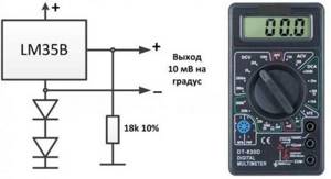
However, at the moment the industry does not stand still, and you can see devices from the 300 series, this is the LM335, which is increasingly recommended by experts and the LM358n. Despite the very low cost, this part occupies the first position in the markings and is oriented towards combination with household appliances. It is worth mentioning that modifications of this part LM 235 and 135 are successfully used in the military and industrial sectors. Including about 16 transistors in its design, the sensor is capable of working as a stabilizer, and its voltage will completely depend on the temperature indicator.
The dependency is as follows:
- For each degree there will be about 0.01 V, if you focus on Celsius, then at 273 the output result will be 2.73V.
- The operating range is limited to -40 to +100 degrees. Thanks to such indicators, the user completely gets rid of adjustments by trial and error, and the required temperature will be ensured in any case.
Also, in addition to the temperature sensor, you will need a comparator, it is best to purchase LM 311, which is produced by the same manufacturer, a potentiometer to generate a reference voltage and an output setting to turn on the relay. Don't forget to purchase a power supply and special indicators.
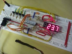
Using Arduino
There are many circuits describing a digital thermometer using an Arduino microcontroller. All of them uniformly take the measured temperature from the sensor and display it on the display, which is quite small in size. That is, of course, such a system can be used outdoors, but the display screen needs to be placed closer to people or even mounted indoors.
What is good about a microcontroller is that not only a digital indicator can act as a scale. Although the latter also has the right to life, for reading readings in places where the street informant is not visible. As for the latter, in its role you can use a long homemade ruler (which can also be an ordinary board of any size), with markings and an arrow moved by a servo drive, demonstrating the current temperature values.
Mechanism
The general design of the mechanism is as follows:
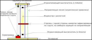
The lower and upper ends of the scale are determined by the physical position of the installed switches, which are closed by a movable pointer when the marked length limit is reached. The latter is required only for the initial calibration of the mechanism when the system is first started.
To ensure that the accuracy of the presented meter is not influenced by external weather factors (the moving string and guide lengthen in the heat and contract in the cold), it is recommended that the upper roller and supporting wire be secured to rigid springs “in tension.”
Scheme
A few notes on the diagram. The TM1637 digital indicator is used to display temperature information numerically. Additionally, the previously described mechanism displays the value on an “analog” scale using a bipolar clock motor M1. S1 is a blocking switch installed at the top of the scale, S2 at the bottom.
Pressing the S3 button once switches the Arduino to search for the zero temperature position (LED1 will light up). The “arrow” indicating degrees will move to the required level to subsequently mark the starting point of measurements. Next, using the established maximum and minimum, using a ruler, mark the rest of the scale below and above zero.
Pressing S3 again will switch the device to standard operating mode. The LED will go out and the arrow will move to the position corresponding to the current temperature.
Power to the ULN2003A is supplied from a source other than the one that supports the operation of the microcontroller itself. The latter was done to avoid interference from parasitic motor currents to the general circuit.
Control sketch
To work with TM1637 you will need the Groove 4Digital Display library, its address:
The sketch can be downloaded here: https://cloud.mail.ru/public/4gRK/ri7sjm19N
Accuracy
Rounding to an integer part in the sketch led to a decrease in the accuracy of the readings to the nearest degree on the analog scale. On the numerical indicator, such a problem is not observed - it displays the resulting temperature correctly.
Scope of application of homemade thermostats
In everyday life, the use of a thermostat is most often found among summer residents who operate homemade incubators and, as practice shows, they are no less effective than factory models. In fact, such a device can be used anywhere where it is necessary to perform some actions that depend on temperature readings. Similarly, you can equip an automatic lawn spraying or watering system, extending light-protective structures, or simply a sound or light alarm that warns of something.
Why do you need a thermostat for an incubator?
In order for young birds to be hatched efficiently in an incubator, it is necessary to regularly maintain humidity and temperature at optimal levels.
Temperature indicators differ depending on the breed of birds and the stage of their incubation; accordingly, they must be regulated. They range from 35 to 39 degrees. And in order to be able to control the temperature, a microcontroller (thermostat) is required. Many modern factory incubators are equipped with analog thermostats, which need to be frequently adjusted depending on the temperature readings. Most often, alcohol or mercury thermometers are used to maintain temperature.
However, digital temperature microcontrollers have more advantages over analog devices:
- the required temperature is ensured inside the device;
- it becomes possible to control the operation of heating elements;
- based on current indicators, you can control the temperature;
- the process is automated and does not require regular adjustments;
- Electricity is saved because when the required temperature is reached, the heating elements are turned off.
The editors of the site advise you to familiarize yourself with the labeling of imported and Soviet ceramic capacitors.
DIY temperature controller: power and load
As for the connection of LM 335, it must be serial. All resistances must be selected so that the total current that passes through the temperature sensor corresponds to values from 0.45 mA to 5 mA. The mark should not be exceeded, as the sensor will overheat and show distorted data.
The thermostat can be powered in several ways:
- Using a power supply oriented at 12 V;
- Using any other device whose power supply does not exceed the above figure, but the current flowing through the coil should not exceed 100 mA.
Let us remind you once again that the current in the sensor circuit should not exceed 5 mA; for this reason, you will have to use a high-power transistor. KT 814 is best. Of course, if you want to avoid using a transistor, you can use a relay with a lower current level. It can operate on a voltage of 220 V.
Assembly and adjustment
When assembling the thermostat, it is necessary to ensure a high-quality connection of all electrical contacts, especially in the power section.
When using a temperature sensor LM-335 or a similar (calibrated) one, there is no need to configure the device, as already noted.
If a thermistor or any semiconductor element is used as a temperature sensor, then adjustments cannot be avoided. It is most convenient to carry it out using a digital thermometer, for example, brand TM-902C.
The sensors of the thermometer and thermostat must be connected using adhesive tape or electrical tape and placed in environments with different temperatures. In this case, each time you need to gradually change the resistance of the variable resistor until the device works. At this moment, you need to record the readings of the digital thermometer and make a corresponding mark opposite the current position of the variable resistor knob.
PCB and design
A miniature printed circuit board was designed for the circuit. I would like to note that only one operational amplifier of the microcircuit is used here - pins 1-3, as well as for power supply - 4, 8.
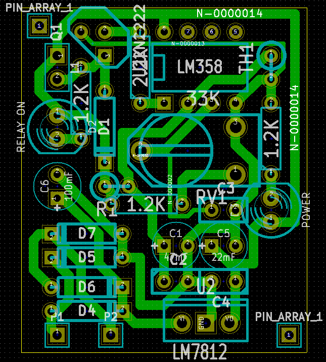
Rice. 4. Arrangement of components on the thermal relay printed circuit board (view from the side of the parts through, showing the tracks).
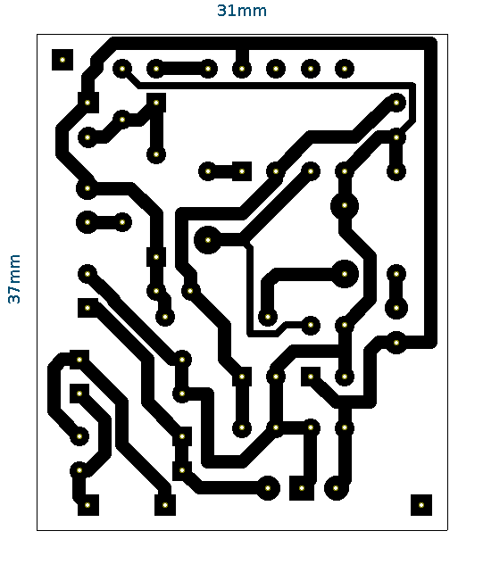
Rice. 5. Stencil of a thermal relay printed circuit board for printing (view from the tracks, mirrored).
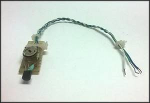
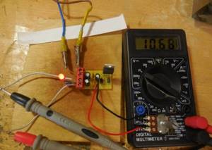
The printed circuit board was manufactured using the LUT method. Below is a photo of the finished thermal relay (thermostat):
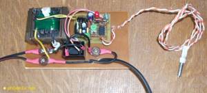
Rice. 6. Photo of the finished thermal relay unit on the LM358 chip.
For power supply, I used a miniature transformer with a power of 4 Watts and two 6V windings, which I connected in series. All components, together with the device’s printed circuit board, are placed on a piece of fiberglass (not foil-coated).
DIY repair
Assembled by hand, these devices last quite a long time, but there are several standard situations when repairs may be required:
- Failure of the adjusting resistor - this happens most often, since the copper tracks inside the element along which the electrode slides wear out, and is solved by replacing the part.
- Overheating of the thyristor or triode - the power was selected incorrectly or the device is located in a poorly ventilated area of the room. To avoid this in the future, thyristors are equipped with radiators, or the thermostat should be moved to an area with a neutral microclimate, which is especially important for wet rooms.
- Incorrect temperature adjustment - possible damage to the thermistor, corrosion or dirt on the measuring electrodes.
How to make a simple thermostat
The manufacture of a thermostat occurs in stages:
- Selecting the type and circuit of the device.
- Purchasing the necessary materials, tools and parts.
- Device assembly, configuration, commissioning.
The manufacturing stages of the device have their own characteristics, so they should be considered in more detail.
Necessary materials
Materials required for assembly include:
- Foil getinax or circuit board;
- Soldering iron with solder and rosin, ideally a soldering station;
- Tweezers;
- Pliers;
- Magnifier;
- Wire cutters;
- Insulating tape;
- Copper connecting wire;
- Necessary parts according to the electrical diagram.
Other tools or materials may be needed during the process, so this list should not be considered exhaustive or definitive.
Device diagrams
The choice of scheme is determined by the capabilities and level of training of the master. The more complex the circuit, the more nuances will arise when assembling and configuring the device. At the same time, the simplest schemes make it possible to obtain only the most primitive devices that operate with a high error.
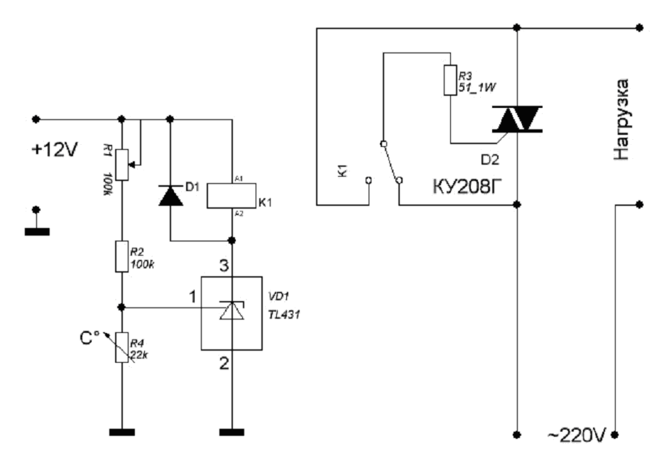
Let's consider one of the simple schemes.
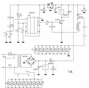
In this circuit, a zener diode is used as a comparator
The figure on the left shows the regulator circuit, and on the right is the relay block that turns on the load. The temperature sensor is resistor R4, and R1 is a variable resistor used to adjust the heating mode. The control element is a zener diode TL431, which is open as long as there is a load on its control electrode above 2.5 V. Heating of the thermistor causes a decrease in resistance, causing the voltage on the control electrode to drop, the zener diode closes, cutting off the load.
The other scheme is somewhat more complicated. It uses a comparator - an element that compares the readings of a temperature sensor and a reference voltage source.
A similar circuit with a comparator is applicable for adjusting the temperature of a heated floor.
Any change in voltage caused by an increase or decrease in the resistance of the thermistor creates a difference between the standard and the operating line of the circuit, as a result of which a signal is generated at the output of the device, causing the heating to turn on or off. Such schemes, in particular, are used to regulate the operating mode of heated floors.
Step-by-step instruction
The assembly procedure for each device has its own characteristics, but some general steps can be identified. Let's look at the build progress:
- We prepare the device body. This is important because the board cannot be left unprotected.
- We are preparing the payment. If you use foil getinax, you will have to etch the tracks using electrolytic methods, having first painted them with paint insoluble in the electrolyte. A circuit board with ready-made contacts greatly simplifies and speeds up the assembly process.
- Using a multimeter, we check the performance of the parts and, if necessary, replace them with serviceable samples.
- According to the diagram, we assemble and connect all the necessary parts. It is necessary to ensure the accuracy of the connection, correct polarity and direction of installation of diodes or microcircuits. Any mistake can lead to the failure of important parts that will have to be purchased again.
- After completing assembly, it is recommended to carefully inspect the board again, check the accuracy of the connections, the quality of soldering and other important points.
- The board is placed in the case, a test run is carried out and the device is configured.
Thermal sensor on germanium diodes
A feature of germanium semiconductor diodes is their high sensitivity to changes in air temperature. Therefore, these radio components can be used as temperature sensors when they are turned back on.
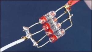
Their use is explained by the strong dependence of the reverse current on the ambient temperature. This feature of the diodes is used in a simple cooler speed controller circuit.
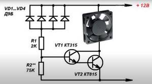
Germanium diodes connected in parallel (3–4 pieces) are connected in the opposite direction to the base circuit of the composite transistor. Their glass cases can be mounted directly on the cooler without any heat sinks. Resistor R1 protects the transistor from thermal breakdown, and R2 determines the response threshold of the regulator. If the fan does not turn on when the room temperature is exceeded, then the number of diodes must be increased. When the cooler begins to rotate the blades at high speed, the number of radio components is reduced.
A little theory
Any thermostat structurally includes three main blocks:
Theoretically, a temperature sensor can be represented by a set of four resistances, among which three resistors will be represented by elements with constant electrical parameters, and the fourth by variable ones. They are assembled into a measuring half-arm circuit shown in Figure 1 below:
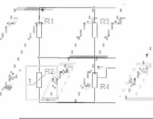
The diagram shows the principle of connecting resistors to obtain a temperature sensor. As you can see, resistance R2 is variable and changes its physical value in accordance with changes in ambient temperature. When the same supply voltage is supplied to the thermostat, when the resistance in the arm changes, the current in the circuit will increase.
Based on the changes, temperature fluctuations are analyzed, as a result of which the working element causes the thermostat to operate and subsequently turn off or turn on the equipment.
To measure the resistance of resistors, a microcircuit operating in comparator mode is installed as a logical element. Its task is to compare the electrical signals in the two arms. An example of a temperature controller circuit is shown in the figure:
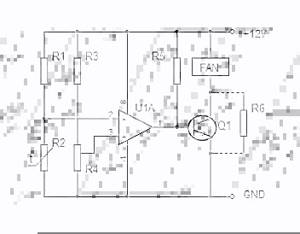
Here, the U1A microcircuit block receives signals from the temperature meter at inputs 2 and 3. When the response temperature is reached, different currents will begin to flow in the arms, and the comparator will send a signal to turn on to the control element of the electronic thermostat.
When the thermometer sensor cools down, the current in the arms of the thermostat will equalize, and the electronic unit will issue a control signal to turn off. The above electronic circuit operates in two stable states - off and on, alternating operating modes occurs in accordance with a given logic.
This thermostat circuit is used in the operation of a personal computer cooler; receiving power from the power supply, the current in the arms is compared. When the power supply overheats, the thermostat will switch the transistor to the opposite state and the fan will start.
This principle can be used not only in fans, but also in a number of other devices:
- to control the operation of electric heating based on temperature readings in the room;
- to set the temperature level in a homemade incubator;
- when connecting a heated floor to control its operation;
- to set the temperature range of engine operation, with forced cooling or shutting down the system when the temperature limit is reached;
- for soldering stations or hand soldering irons;
- in cooling systems and refrigeration equipment with the logic of reducing temperature within certain limits;
- in ovens and stoves for both household and industrial purposes.
The scope of application of the thermostat is not limited in any way; wherever you want to control the temperature level in automatic mode with power management, such a device will be an excellent assistant.
How to install correctly
To extend the life of the thermostat, use the following recommendations:
- do not install electronics without additional protection outdoors or in rooms with high humidity levels;
- if necessary, remove the control sensor into an unfavorable environment;
- exclude the placement of the regulator opposite heat guns or other “generators” of cold or heat;
- To increase accuracy, choose a location without active convection currents.
Advantages and disadvantages
Even a simple do-it-yourself thermostat has a lot of advantages and positive aspects. There is no need to talk about factory multifunctional devices at all.
Temperature regulators allow:
- Maintain a comfortable temperature.
- Save energy resources.
- Do not involve a person in the process.
- Follow the technological process, increasing quality.
The disadvantages include the high cost of factory models. Of course, this does not apply to homemade devices. But the production ones, which are required when working with liquid, gaseous, alkaline and other similar media, have a high cost. Especially if the device must have many functions and capabilities.
When equipping a cellar, it is necessary to create a temperature regime at which all reserves will be stored for as long as possible. And to maintain it, you will need a thermostat - a device that helps maintain the set temperature. This device is used in many household appliances: irons, refrigerators, soldering irons. How to make a thermostat for a cellar with your own hands?
( 1 rating, average 5 out of 5 )
Settings
To measure temperature, it is better to use a thermistor, whose electrical resistance changes as the temperature changes.
It should be noted that the version of the thermostat indicated in our article, created from the LM335 sensor, does not need to be configured.
It is enough just to know the exact voltage that will be supplied to the “plus” of the comparator. You can find it out using a voltmeter.
The values needed in specific cases can be calculated using a formula such as: V = (273 + T) x 0.01. In this case, T will indicate the desired temperature, indicated in Celsius. Therefore, for a temperature of 20 degrees, the value will be 2.93 V.
In all other cases, the voltage will need to be checked directly experimentally. To do this, use a digital thermometer such as TM-902S. To ensure maximum accuracy of adjustment, it is advisable to attach the sensors of both devices (meaning a thermometer and a thermostat) to each other, after which measurements can be taken.
Watch a video that popularly explains how to make a thermostat with your own hands:
Andrey
, perhaps the whole problem is in the KU208G triac. 127V is obtained from the fact that the triac skips one of the half-cycles of the mains voltage. Try replacing it with an imported BTA16-600 (16A, 600V), they work more stable. It’s not a problem to buy a BTA16-600 now, and it’s not expensive.
sta9111
, to answer this question you will have to remember how our thermostat works. Here is a paragraph from the article: “The voltage at control electrode 1 is set using a divider R1, R2 and R4. A thermistor with negative TCR is used as R4, so when heated its resistance decreases. When the voltage at pin 1 is above 2.5V, the microcircuit is open, the relay is turned on.”
In other words, at the desired temperature, in your case 220 degrees, thermistor R4 should. The voltage drop is 2.5V, let's denote it as U_2.5V. The rating of your thermistor is 1KOhm - this is at a temperature of 25 degrees. This is the temperature indicated in the reference books.
Reference book on thermistors msevm.com/data/trez/index.htm
Here you can see the operating temperature range and TKS: for a temperature of 220 degrees, little is suitable.
The characteristic of semiconductor thermistors is non-linear, as shown in the figure.
Drawing. Volt-ampere characteristics of the thermistor - website/vat.jpg
Unfortunately, the type of your thermistor is unknown, so we will assume that you have an MMT-4 thermistor.
According to the graph, it turns out that at 25 degrees the resistance of the thermistor is exactly 1KOhm. At a temperature of 150 degrees, the resistance drops to approximately 300 Ohms; it is simply impossible to determine more precisely from this graph. Let's denote this resistance as R4_150.
Thus, it turns out that the current through the thermistor will be (Ohm’s law) I= U_2.5V/ R4_150 = 2.5/300 = 0.0083A = 8.3mA. This is at a temperature of 150 degrees, it seems that everything is clear so far, and there seem to be no errors in the reasoning. Let's continue further.
With a supply voltage of 12V, it turns out that the resistance of the circuit R1, R2 and R4 will be 12V/8.3mA=1.445KOhm or 1445Ohm. Subtracting R4_150, it turns out that the sum of the resistances of resistors R1 + R2 will be 1445-300 = 1145 Ohms, or 1.145 KOhms. Thus, you can use a tuning resistor R1 1KOhm, and a limiting resistor R2 470Ohm. This is how the calculation turns out.
This would be all well and good, but few thermistors are designed to operate at temperatures up to 300 degrees. Thermistors ST1-18 and ST1-19 are most suitable for this range. See reference msevm.com/data/trez/index.htm
Thus, it turns out that this thermostat will not provide temperature stabilization at 220 degrees and above, since it is designed for the use of semiconductor thermistors. You will have to look for a circuit with metal thermal resistances TSM or TSP.
The reason for assembling this circuit was the breakdown of the thermostat in the electric oven in the kitchen. Having searched on the Internet, I didn’t find a particular abundance of options on microcontrollers, of course there are some, but all are mainly designed to work with a temperature sensor like DS18B20, and it is very limited in the temperature range of upper values and is not suitable for the oven. The task was to measure temperatures up to 300°C, so the choice fell on K-type thermocouples. Analysis of circuit solutions led to a couple of options.
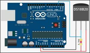
Using a thermal sensor on Arduino
To assemble a temperature meter based on an Arduino microcontroller, you need to prepare the following:
- Arduino UNO;
- connectors;
- circuit board;
- digital module DS18B20 (range from −56 to +1250 C).
The DS18B20 digital temperature sensor is a device that not only signals when a specified temperature threshold has been exceeded, but can also store measurement values. The sensor chip has three output contacts - “+”, “−” and a signal wire. The waterproof temperature sensor is used to measure the heating of water or liquids.
A temperature sensor can always be purchased, like an Arduino board, in online stores. The digital module is connected to Arduino via GND channels, and the Vdd output is connected to 5V, Data to any Pin. For a clearer understanding, the connection diagram of the DS18B20 digital sensor to Arduino is shown in the photo below.