The pumping and mixing unit and the manifold group of the water heated floor are designed to regulate the circulation of the coolant in the circuits, control the pressure in the heating system, eliminate air pockets and control the temperature. How the manifold for a heated floor is assembled, the basic connection diagrams and common mistakes, we will consider further. You can read about the device and principle of operation here
Why do you need a heated floor collector?
The “water heated floor” system is an effective way to uniformly heat all rooms in the house. Installation of this type of heating without a collector group is possible provided that a single circuit is laid. However, the maximum possible length of one pipe should not exceed 70 m, which effectively covers seven square meters. Thus, on average, a minimum of 2 circuits will be required per room.
Pumping and mixing unit with a minimum number of circuits
When laying water heated floors simultaneously in several rooms without turning on the collector, it will be impossible to regulate the main indicators of the correct operation of the heating system. The absence of a collection group is fraught with serious problems:
- Inability to regulate pressure in the heating system and bleed air;
- If the water heated floor pipe is damaged, you will have to turn it off completely in the entire house;
- Uneven heating of the premises of the house.
Improper functioning of the system will lead to costly repairs. If you have some skills, it is possible to install the unit without involving specialists. It is enough to purchase a manifold group that matches the parameters of the pumping and mixing unit and connect them in compliance with the technology.
Purpose of valves
A two-way valve can only allow water to flow in one direction, but its flow capacity is low. Its main advantage is the smooth supply of coolant. Modern models have a servo drive, which allows you to precisely adjust the throughput hole; this is done using a motor and a valve position sensor.
Two-way valves have a small capacity, so they can be used in rooms whose area does not exceed 200 m2.
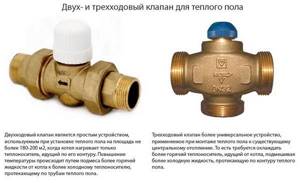
A three-way valve can mix and separate water flows, which is why it is also called a mixing valve. It has three pipes, one where water comes from the boiler, another where it is supplied to the system, and one where the return flows and mixes it again with hot water. Such elements are installed in autonomous heating systems at the outlet of the collector.
During operation of the heated floor, the valve becomes clogged and for ease of replacement, a detachable coupling is used.
What does a heated floor manifold consist of?
The control system for a water heated floor is a combination of valves, sensors, actuators and other elements. The principle of operation of the collector is simple - the heated coolant passes through the circuits, cooling and returning to the starting point for reheating. The design mixes circulating liquid of different temperatures, which allows you to obtain optimal parameters for heated floors.
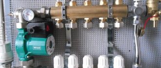
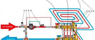
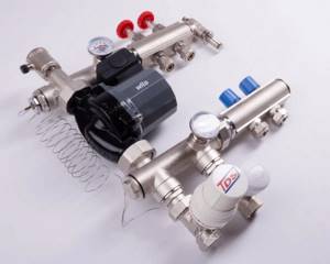
A standard mixing and distribution unit for a heated floor assembly consists of:
- Mixing unit (1) for diluting hot water from the boiler. Mixing occurs automatically due to the presence of temperature sensors and a servo drive used as a thermostat.
- Circulation pump (2) on the coolant supply pipe. The pump provides the system with the correct pressure to improve heating efficiency;
- Distribution comb (collector group) (3), equipped with outlets for connecting water circuits and flow meters for zonal distribution of circulating fluid through pipes. As well as a bypass (5) to prevent overheating of the pump.
Design and principle of operation of the collector
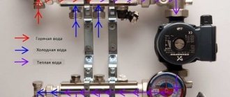
The manifold, or comb as it is also called, is included in the mixing unit kit. Without this device it is difficult to imagine a normally functioning heated floor. Without this device, the whole point of heating through underfloor heating is lost. Being the most important element of the mixing unit, the manifold ensures the mixing of water flows of different temperatures and their subsequent distribution through the heating pipes of the water circuit. Essentially, the device consists of two similar parts, one part is the supply part, while the other is the collecting part. Hence the name, which is common among specialists, distribution comb.
For reference: the distribution part is the unit for supplying warm water to the underfloor heating pipeline system. The collecting part is specially designed to collect waste coolant flowing in the opposite direction (return).
Structurally and externally, both parts are practically no different. The device is based on a large diameter tube equipped with threaded side branches (holes). The number of holes corresponds to the number of water circuits connected to the equipment. In simple terms, a comb is tees with the same parameters, twisted together. Therefore, for those who have at least some idea about plumbing, making a homemade manifold will not involve a pipe.
Having an idea of what a collector is and what its main tasks are, you can start planning your own heating system. In order to make a distributor, you need to know in advance how large the heated room will be and what your heating needs are. Therefore, decide the following questions for yourself:
- how many heating circuits will you have;
- what type will be the main source of water heating (we are talking about either a central heating and hot water system, or an autonomous boiler);
- what additional devices and devices will be equipped with the heating system (pump, temperature sensors, pressure gauges).
Note: you need to start making a heated floor collector with your own hands by choosing the design of the device. In other words, it is necessary to decide how the water pipes will be connected, and accordingly in what position the distribution and collecting combs will be located.
* There are a lot of technological nuances that you should pay attention to before you start assembling your device.
For example, gas or electric heating devices are connected to the collectors from below or from above. When installing a circulation pump in the system, the connection will only be at the end of the comb.
In cases where you use an indirect heating boiler or solid fuel boilers as a heating device, the collector can only be connected from the end.
If you want to use water from the central heating system to operate heated floors, your collector must be connected from above or below. The diagram shows an option for connecting the collector to the riser of the central heating system.
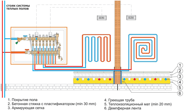
If it’s not difficult for you, transfer the design diagram and the position of the distribution combs onto paper. At the same time, you can specify the dimensional parameters that you can rely on during the work process. It is appropriate to say here that the distance between the individual supply and return pipes should be at least 10 cm and no more than 20 cm. The same dimensions can also be used for the distance between the individual units, the collection comb and the distributor.
Note: Try to make your device not only efficient and technologically advanced, but also compact. Otherwise, you may later face the problem of installing a homemade collector. An oversized device is more difficult to hide in a collector box, and installation of a heated floor collector will negatively affect the interior of the heated room.
After drawing up a sketch, it will become clear how much and what you will need for further work on making a homemade switchgear.
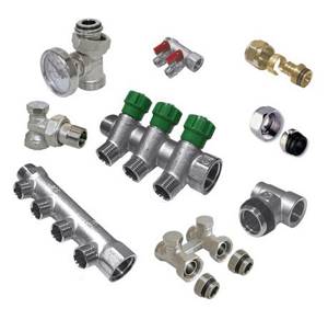
Accessories for water heated floors
The complex design of the mixing unit and collector group is complemented by many auxiliary parts that play one or another role in regulating the operation of warm water floors:
- The thermostatic valve is controlled manually or automatically using an electrothermal drive.
- Hydraulic balancing of the loops of the underfloor heating system occurs through tuning valves (there are options with or without flow meters).
- Ensuring constant pressure is achieved using an overflow valve, which redirects excess liquid to the bypass.
- The radiator balancing shut-off valve is used to open/close the water supply between the collector and the heating system.
- A bypass with a bypass valve, an expansion tank, a safety valve, as well as communicators and controllers are responsible for the trouble-free operation of water-heated floors and continuous monitoring of the operation of the heating system.
The mixing unit may have two or three way mixing valves. The first option is considered more reliable, as it allows you to limit the flow of water directly from the boiler using a balancing valve and thermostatic control units. This protects the circuit from exposure to boiling water, which is especially valuable when using polypropylene pipes.
The 3-way valve design is more versatile in terms of recommended heating area. Unlike two-way units, which cannot serve more than 200 m², a three-way valve creates optimal pressure in heated floors of any size.
Settings
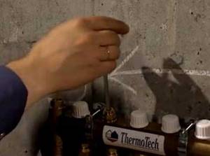
As a rule, a special balancing table is attached to the diagram, on the basis of which the comb can be adjusted according to two parameters: circuit length and heating load.
The table relates the circuit number and the number of revolutions from the position of the balancing valve - “closed”. Set up the comb like this:
- remove the cap from the valve that serves to protect it;
- close the valve all the way - use a hex key for this;
- determine the number of revolutions for a given circuit;
- turn off the valve to this number;
- The remaining circuits are configured in the same way.
Correct configuration and connection of the collector are necessary for long-term operation and efficient operation of the system.
Assembly of the finished kit
The simplest and most reliable way, but more expensive, is to buy a ready-made set of pumping and mixing unit and manifold group. The assembly manual for the factory kit contains step-by-step instructions, allowing even an inexperienced craftsman to assemble it with his own hands.
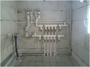
Assembling a complete set of pumping and mixing unit and manifold group
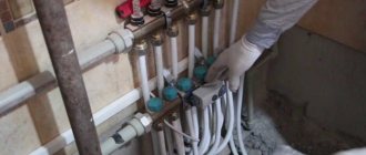
The connection of underfloor heating pipes to the collector is made taking into account the throughput of the distribution combs and a drawn up diagram indicating the sizes of the pipes, their connection points with the elements of the heating system and the places of installation. Work on connecting the water circuit is carried out after installing the collector and protection system (bypass, air valve).
The process of assembling a homemade manifold
If your heating system is concentrated in one room and for this you only need one water circuit, start assembling a simple collector. For these purposes you will need:
- ¾ inch mixing valve;
- ¾ inch adapter;
- nipple;
- tees;
- elbow with a bend angle of 900;
- ¾ inch clamping coupling.
As additional equipment, you will also need a circulation pump with an inlet with 1-inch diameter pipes, a ¾-inch ball valve, air vents and a drain valve.
To make a manifold with your own hands, you can use brass components or metal-plastic valves, elbows, tees and adapters. Metal-plastic shut-off valves used for these purposes are cheaper and make it easy to improve the design of a heated floor, with the expectation of increasing the contours of the heated floor.
* It is better to use round and square pipes for return supply and collection units. Metal pipes of rectangular cross-section are considered the best option, since, according to experts, removing them is more convenient to work with. Let's look at how to assemble a homemade manifold from metal-plastic pipes.
The manufacturing and assembly process can be divided into stages.
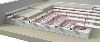
First stage: in accordance with the dimensions indicated on the sketch, pipes are prepared from which individual fragments of the structure will be made.
Second stage: individual elements are combined into a single structure in accordance with technological need and purpose;
Third stage: installation of individual elements is carried out in places prepared for cold welding. Next, welding work is carried out using a cold welding machine;
Fourth stage: having assembled your own collector, you need to check it for leaks. Having closed all the pipes, one is left open to supply hot water. The absence of leaks at the connections indicates that you did everything correctly;
Fifth stage: installation of the collector at its permanent location and connecting the heating pipes of the water circuit to it.
Next, as necessary, the mixing unit is equipped with a circulation pump, a three-way valve and other elements of shut-off valves.
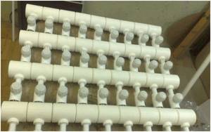
Manifold made of polypropylene pipes
If polypropylene pipes are used for production, you should pay attention to the presence of a reinforcing layer in them. In its absence, the plastic structure may be subject to deformation due to the current temperature conditions.
Detailed technical process for assembling the collector group:
Assembling a collector comb from polypropylene pipes
Mixing units made of polypropylene have an important advantage over their metal “counterparts” - low cost. Otherwise, you will have to come to terms with a number of shortcomings:
- Polypropylene manifolds are installed in systems with a small number of outlets (no more than 5 pieces);
- Flow meters cannot be installed;
- A larger protective box is required due to the massive structure;
- Be sure to have a set of specialized tools and soldering skills.
Assembling a distribution manifold from individual elements
For those who do not have special tools, you can assemble a comb from separate ready-made elements. It is better to select components from one manufacturer.
The circuits are connected according to the chosen scheme, adhering to the main rule - pipes with warm coolant are fixed at the top. Pipes with cooled coolant are secured from below.
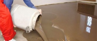
At the final stage, it is necessary to carry out pressure testing and a control start-up of the heating in order to timely identify hidden or obvious deficiencies in the structure made.
Tips for installing a warm water floor collector
Using a factory kit eliminates a number of common mistakes when installing a unit. The finished manifold group for underfloor heating is already equipped with the necessary valves and other important elements.
Be sure to consider the following recommendations:
- The calculation of the thermal load on the circuit is calculated before installation, and based on the data obtained, the balancing valve is adjusted;
- The cabinet for the mixing unit is placed in a place located at the same distance from the connected pipes;
- The dimensions of the collector box should be selected according to the dimensions of the device;
- Under the block, be sure to provide space for bending each contour;
- For a possible increase in water circuits, it is worth leaving several free pipes;
- The most efficient heating system is obtained by introducing a powerful circulation pump;
- When installing multiple pumps, be sure to use check valves.
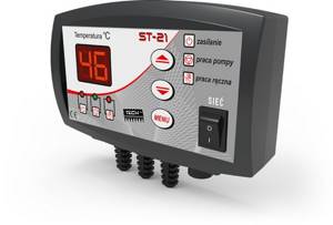
Circulation pump control
In order to ensure a certain speed of the coolant in the floor line, a circulation pump is installed on the output circuit. It is designed to pump cooled liquid into the heat exchanger located in the boiler.
For each branch of the main it is recommended to install its own circulation pump with its own thermostat. This is necessary in order to be able to control the temperature individually in a specific room.
If the underfloor heating is equipped with only one pump and one control unit, the heating will be maintained at the same level in all rooms. The system will turn off not only in a room where the temperature is higher than normal, but also in a room with a lower temperature. Automation for underfloor heating, which controls the operation of the pump, is represented by the following elements:
- temperature sensor; the equipment is installed on a chilled water circuit; it transmits data to the thermostat;
- thermostat; the equipment is designed to analyze the temperature that was set for a certain room and the data transmitted from the sensor; when the indicators decrease, the thermostat turns off or turns on the circulator;
- hysteresis; the device ensures harmonious operation of the system; a reserve temperature range is set; it can be from +/-1 to +/-10 degrees; if the thermostat was set to 30 0C, the hysteresis is +5 0C, then the pump will turn off at a temperature of 25 0C; it will turn on when the coolant is heated to 35 0C;
- uninterruptible power supply unit UPS or generator; the equipment will ensure constant operation of the pump and automatic control, regardless of the power supply.
We recommend: How to make a warm floor from central heating?
Instead of a temperature sensor, a pressure switch is installed on the circulator. The device determines the intensity of coolant supply into the main line. Water circulates in the system at a pressure of 4-6 bar. When the indicator increases, the relay turns off the pump. Water enters the system at low pressure, which reduces the heating intensity. When the pressure in the line decreases, the relay turns on the circulator.