VALTEC SrL was founded in Italy in 2002 and specializes in the production of equipment for thermal systems operating in difficult conditions. Currently, it is highly respected among consumers in various countries, including Russia. In terms of price, it is considered affordable for most users and fully meets European quality standards.
VALTEC
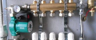
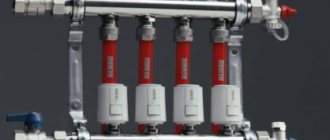
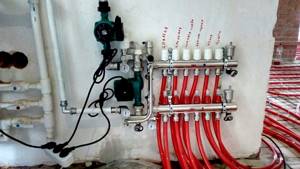
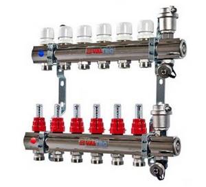
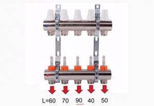
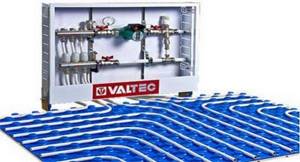
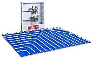
Valtec underfloor heating manifold with rotameters
The parts are made of CW617N brass and AISI 301 stainless steel. The manifolds have adjustment and shut-off valves, drain valves, and automatic air vents. All seals are made using EPDM rings, the standard for connecting Euroconus pipe loops. Some models have additional equipment that allows you to fully automate the operation of the devices. The number of outlets ranges from 2 to 12, diameters 1″ and 1 1/4″. The warranty on all company equipment is 7 years, maximum operating temperature is +120°C, optimal pressure is 10 Bar.
How to install underfloor heating
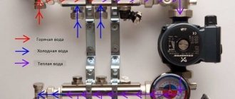
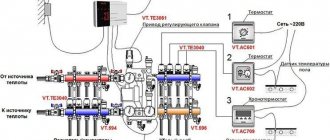
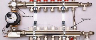
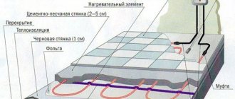
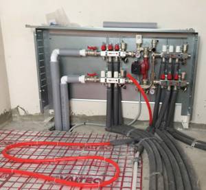
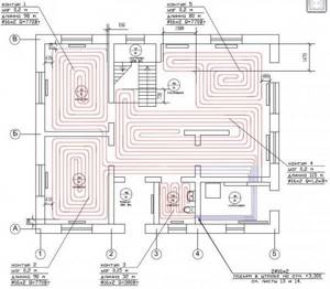
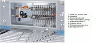
Valtek trains specialists in installing heating systems in Moscow and many CIS cities. They connect the system and test the equipment. Installation diagram for water heated floor:
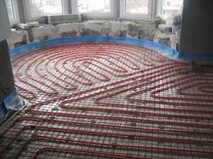
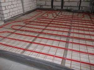
- Valtek thermal insulation is laid on a flat concrete surface;
- a damper tape is mounted to the wall; it is made of foamed polymer; necessary to compensate for the expansion of the material; to block heat waves;
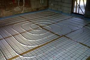
- 16*2 mm pipes are laid on the insulation; use the “snake” or “snail” technique and strengthen the contour with metal staples;
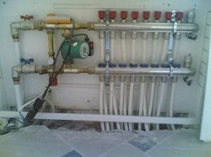
- connect the circuit to the collector group; separate outlets for hot and chilled water;
- 1” ball valves are installed at the outlet to the manifold; there are 2 of them; on hot and cold circuits;
- a 26*3 mm pipeline is removed from the collectors;
- a circulation pump with a ball valve is installed on the hot water pipe;
- then, connect a three-way mixer with a thermal head and sensor;
- lead a pipe with hot water to the boiler;
- You can separately make a line to the radiator heating, if there is such a need;
- lay pipes with chilled water from the collector to the boiler;
- excess liquid is drained into a storage tank; a separate line is provided for it; the DHW circuit can be removed from the storage tank for household needs;
- a water filter and a check valve are installed on the pipe that leads from the tank to the boiler;
- connect hot and cooled pipes to the boiler; for this purpose, separate pipes are provided in the heating unit; they are connected to a heat exchanger.
Underfloor heating is a good alternative to radiator heating. The heat is evenly distributed throughout the entire volume of the room, creating a comfortable microclimate. The system is safe and durable. When using automatic control, it is easy to operate.
How to assemble a collector?
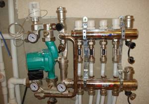
The Valtec distribution block is manufactured assembled. Flow meters are already installed on the hot tube. There are thermal heads on the cold line, but the product may only have outputs for attaching temperature control devices. They are protected by plastic caps. The manufacturer gives you the opportunity to choose which automation to install: thermal head, servo drive.
Some small elements need to be connected to the collector group:
- On the right, shut-off valves are connected to the tubes. There are 2 of them in the set.
- A float device is connected to the valves to remove air.
- Opposite the air vents, drain valves are connected to the underside of the tubes.
- The ends of the comb are closed with plugs.
We recommend: How to install infrared heated floors?
A circulation pump and a three-way or two-way valve are separately connected to the comb. These devices must be purchased separately. They are connected on the left to the tube into which the cold coolant flows. Use brass threaded fittings.
The cold and hot circuits are removed from metal pipes that are connected to the boiler or furnace. They are connected via a bypass at the outlet of the collector group. A circulation pump with a temperature sensor is installed between the circuits.
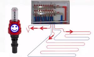
The rotameter is adjusted when testing the heating system. The protective sleeve must be removed from the device. Using the red ring, the upper bushing, set the rotameter to zero.
Next, using the same bushing, install the valve on the o for large rooms, on the o for small rooms. To fix the rotameter parameters, turn the lower ring to the right until it stops.
Return the protective cap to its original place. The rotameter may not have a locking ring. In this case, the pipeline fill indicator is set without fixing. Valve operation must be checked regularly.
Valtek collectors for heated floors are installed with a liquid heating system. The coolant can be water, antifreeze, glycol fillers that do not freeze at low temperatures. If the heating system is not used, then the coolant does not need to be drained.
The number of circuits on the distribution block is 3-12 pcs. If necessary, additional equipment can be connected to them to increase the flow capacity of the coolant to all rooms in the house.
The comb is mounted on the wall or placed in a manifold cabinet. The manufacturer provides a 10-year warranty on the equipment. Service centers are located in St. Petersburg and Moscow. The block will last more than 50 years.
If necessary, the rotameter or thermal head can be replaced without turning off the heating system. When using a programmable thermostat, the operation of the heated floor control unit can be carried out through electronic gadgets.
We recommend: How to install heated flooring under laminate on a concrete floor?
YouTube responded with an error: The request cannot be completed because you have exceeded your quota.
- Related Posts
- Which plasticizer to choose for heated floors?
- How does the underfloor heating calculator work?
- How much does underfloor heating cost?
- Features of Legrand heated floors
- How to make a warm floor from central heating?
- What is the difference between Unimat heated floor models?
How does a mixing unit work?
Choosing a boiler for a warm water floor, characteristics of types, scope of application
Before being distributed into the manifold, the hot coolant enters the mixing system, where a thermostat measures its temperature. If the value exceeds the permissible value, the safety valve opens and prevents cold and hot water. When the liquid reaches the desired temperature, the valve stops supplying hot water.
As a rule, the mixing unit not only provides a comfortable temperature regime, but also serves to raise the pressure level in the circuit, which improves the circulation of the coolant. The mixing unit diagram includes:
- Safety valve;
- Circulation pump;
- Bypass;
- Air outlets;
- Valves for stable operation of circuits (shut-off, drainage).
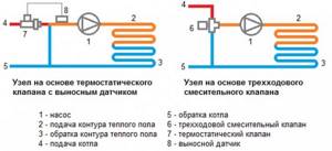
The mixing unit diagram can have a different design. Schemes with two- and three-way valves are more popular.
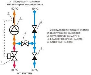
Diagram with two-way valve
A thermostat equipped with an infrared sensor is installed on the two-way (supply) valve, which measures the temperature of the liquid entering the heated floors. The water in the mixing system moves in a circle, and the fuse head regulates the valve that opens or closes the passage of hot water. This is how the process of mixing liquids of different temperatures occurs.
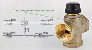
Three-way valve in the mixing circuit
The three-way valve is a universal equipment. It performs the functions of both a bypass valve and a bypass. Its peculiarity is that hot water interferes with the return flow inside the housing. This type of unit is equipped with servos, thermostats, and weather-dependent controllers. The latter are capable of checking the temperature outside every 20 seconds. If the temperature of the water that enters the underfloor heating system does not correspond to the desired temperature, the valve automatically turns 45° in one direction or another.
The three-way design, however, is imperfect and has its drawbacks:
- Presence of excess pressure;
- Possibility of hot water inlet;
- Large throughput, leading to significant fluctuations in coolant temperature.
Sudden changes in pressure and temperature can lead to rupture of underfloor heating pipes.
Mixing unit for Valtec underfloor heating for one circuit (up to 20 sq.m.)
Specification
- 1 – Mixing valve MIX 03 3/4” – 1 piece;
- 2 – Nipple adapter 1-3/4” (VTr.580.N.0605) – 1 pc.;
- 3 – circulation pump with 1” union nuts;
- 4 – adapter nipple 1-1/2” (VTr.580.N.0604) – 1 pc.;
- 5 – ball valve internal-external. 1/2 (VT.218.N.04) – 1 piece;
- 6 – connector with ext. threads 16-1/2 (VTm.302.N.001604) – 2 pcs.;
- 7 – foot 3/4-1/2” (VTr.581.N.0504) – 1 piece;
- 8 – barrel 1/2” 60 mm (VTr.652.N.0406) – 1 piece;
- 9 – tee 1/2 in. (VTr.130.N.0004) – 1 piece;
- 13 – ball valve external-external. 1/2 (VT.219.N.04) – 1 piece;
Connection
Using connectors (6), a metal-plastic pipe for a heated floor with a diameter of 16x2 is connected. The high-temperature circuit supply (boiler supply) is connected to terminal 10, and the boiler return is connected to terminal 11.
This is the simplest and cheapest solution for heated floors. This Valtec mixing unit should additionally be equipped with an automatic air vent. It is advisable to install American taps at the inlet and outlet of the heating system 10, 11.
Description of the elements of the collector group
Types of thermal heads for adjusting heated floors, their design and installation options
produces heating equipment for heating systems, radiator and floor. For water heating, a pipe and perforated insulation with fastening elements for the liquid line are purchased.
The pipes are connected to a comb, which consists of supply and return manifolds. What does a Valtec fluid distribution block provide?
- Supply manifold; a line with hot coolant is connected to it.
- The unit is equipped with flow meters that monitor the filling of the floor water circuit.
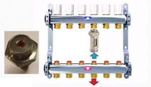
- An end tube with a float device is used to remove air.
- On the return circuit there are outputs for installing a thermal head. If the head is faulty, it is removed for repair. At the same time, the “warm floor” heating system operates in normal mode, without draining the coolant. The thermal head can be replaced with a servo drive or other control device.
- Flow meter valves; they are not permanently mounted on the hot water bar. A threaded connection is provided for them. If necessary, they can be removed.
- The system is equipped with a float device for air removal. A shut-off valve is connected to it, which allows you to remove the float if necessary.
- A drain valve is designed to remove coolant from the heating system. It has a hinged design.
- To ensure that the installation of the collector block for underfloor heating “Valtec” does not cause difficulties, the equipment kit includes adapter nipples and fittings. They are equipped with heat-resistant rubber gaskets.
- The operating temperature of the comb is 90 0C.
- Optimal pressure 8 bar.
- The filling level of the main line is 2.5 m3/h.
Systems that do not include flow meters are cheaper, but if, along with large rooms, the mains of a bathroom or bathroom that are small in size are connected to the comb, then a device for filling the water circuit is necessary.
Along with a thermal head or servos, it regulates the filling of the water circuit and the room temperature. The flow meter is a valve. It closes, preventing hot water from entering a certain circuit. The device is triggered if the coolant flow exceeds the permissible limit.
The Valtek manifold for heated floors is made of stainless steel or nickel-plated brass. Fittings are made from hot-stamped brass. The air vent float is made of polypropylene.
- The size of the collector group depends on the number of outputs. If the block provides 3 outputs, then the length of the tube is 230 mm. With 7 outlets, the comb has a length of 430 mm.
- The pitch between the outlets is 60 mm.
- Outlet size 1”.
The comb is mounted on the wall using brackets. They have a figured design. The edge that fits tightly to the wall surface is provided for the cold circuit. A tube with hot coolant is fixed on the protruding surface.
Equipment and capabilities
Products are manufactured under the Valtec brand by an Italian company. They have been on the Russian market since 2003, so they know our realities first-hand. We produce a wide range of plumbing engineering fixtures and devices. And collectors for heated floors are among them.
general description
The Valtec underfloor heating manifold is made of brass or stainless steel. Or rather, most often, the body is made of stainless steel, and the “filling” is made of brass. In the catalog they are called a manifold block, since there are a couple of devices - for the supply and for the return pipeline. Complete kits are equipped with:
- there are flow meters on the feed comb;
- on the return pipeline there are manual shut-off valves.
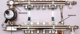
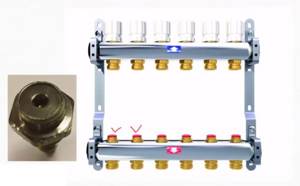
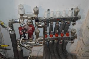
Below is the supply and there are flow meters. At the top is the return pipeline, manual valves are installed
In this option, using flow meters, you can adjust the coolant flow in each of the loops, and manual valves on the return pipeline serve to block circulation. But this configuration can be automated. To do this, servo drives are installed on manual valves, which are connected to thermostats installed in the premises. In this way, a constant floor or air temperature can be maintained. Depends on where the heat sensors are installed, because the thermostat reacts to their readings.
An automatic air bleeder is also installed on the Valtec manifold. This is a device that allows you to remove air trapped in the coolant automatically.
Range
All collector blocks for Valtek underfloor heating can be divided into two groups: with and without adjusting flow meters. There are only three options in the first group and two in the second, but in each the number of connected taps is from two to twelve.
- With flow meters on supply
- VTc.594.EMNX. Body - stainless steel AISI 304, fittings - brass CW617N, seals - EPDM 70Sh, number of outlets - from 2 to 12. Operating pressure 8 bar, nominal diameter of manifolds - 1 inch, outlets - 3/4″ external thread, connection - eurocone. Price - from 9 thousand rubles. (for 2 outputs), up to 25 thousand (for 12 outputs).
- VTc.589.EMNX. Manifold for propylene glycol systems. Body - AISI 304 stainless steel, brass fittings and EPDM 70Sh rubber seals. Working pressure 9 Bar, coolant temperature not higher than 90°C. The nominal diameter of the collectors is one inch, the outlets are 3/4 inch with a Eurocone.
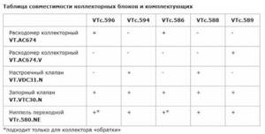
Compatibility table for various Valtec manifolds with components
- VTc.596.EMNX. Valtec brass manifold (CW617N brass) with nickel plated. EPDM 70Sh seals, fittings made of the same brass. Working pressure 10 Bar, outlet connection - Eurocone, diameter 3/4″.
- nominal collector diameter 1 inch, number of outlets from 3 to 12. Price from 12 thousand rubles. for 3 exits, up to 38 thousand rubles. for 12 exits;
- nominal collector diameter 1 and 1/4 inches, number of outlets from 4 to 12. Price from 9 thousand rubles. for 4 exits, up to 45 thousand rubles. for 12 exits.
- With manual valves
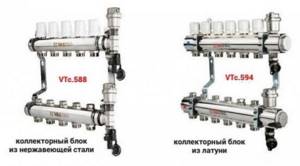
- VTc.588.EMNX. Stainless steel underfloor heating manifold VTc.588.EMNX with thermostatic valves. Coolant - water or propylene glycol, operating pressure 9 Bar, temperature 90°C. There are manual adjustment valves on the supply side. The number of outputs is from 3 (6 thousand rubles) to 10 (15 thousand rubles), connection via a 3/4″ eurocone, nominal collector cross-section is 1″.
- VTc.594.EMNX. Valtec brass manifold for systems with elevated temperatures - up to 120°C, pressure 10 Bar. Includes manual balancing valves and thermostatic ones.
- nominal diameter of the collectors is 1″, the number of outlets is from 3 (10 thousand rubles) to 12 (27 thousand rubles);
- collectors with a cross section of 1 and 1/4″, the number of outlets from 4 (16 thousand rubles) to 12 (36 thousand rubles).
The basic package includes manifold plugs, automatic air vents, drain valves (for filling or draining coolant), and brackets for installation.
Performing preliminary calculations
7 tips on which cross-linked polyethylene pipes for underfloor heating, heating and water supply are best to choose
Before you begin arranging a flooring system in your home, it is imperative to perform preliminary calculations. They will form the basis for selecting products and drawing up a diagram for installation. Products manufactured by Valtek also have an advantage in this regard, since consumers are offered optional configurations.
Sectional view
First, the optimal power indicator is calculated, which depends on the diameter of the pipes, the thermal conditions used during operation and many other factors. Also, the final result of the calculations may be affected by the presence or, conversely, absence of the main type of heating.
For example, the rated power level of well-insulated rooms ranges from 90 watts/m2 to 150. Residential spaces require lower values, and types of rooms that experience high levels of humidity, such as bathrooms, kitchens and washrooms, require higher values. .
The specific power indicator is directly dependent on the pitch with which the system pipes are laid. Most often, the range of 15-30 cm is taken as the desired distance.
Pipeline
The large diameter of the pipes increases the heating area. This occurs due to the fact that a larger amount of coolant passes through the cross section. The most optimal pipeline diameter is 1-2 cm.
Features of setting up a Valtec manifold without flow meters
If the manifold is not equipped with flow meters, but only with valves, you will have to set the flow rate by touch. This is not figurative, but literally. Knowing the length of each circuit, we open the flow to the maximum on the longest one. We screw the rest approximately. You can count the number of valve revolutions and focus on them.
Manifold for underfloor heating without flow meters
Next, we turn on the heating and wait until the floor warms up. If you have a thermometer, measure the floor temperature in the operating area of each circuit. There is no thermometer - we feel and compare sensations. Based on the results, we adjust the position of the valves and wait again for several hours. We continue this way until we are satisfied with the result. In principle, a Valtec manifold with valves without a flow meter is not that difficult to configure.
Evaluating collector settings based on return temperature
This check is based on the fact that with a correctly adjusted flow rate, the return temperature on all circuits should be the same. To set up or check this type, you need special thermometers. They are installed on the return pipeline between the manifold inlet and the pipe.
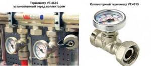
You can adjust the collector using a return thermometer
The temperature of the longest circuit is taken as a reference - all the others are adjusted to it. Only the adjustment results will need to be corrected after a few hours. When the floor heated by adjustable circuits warms up or cools down (depending on the adjustment) and the temperature in the return pipe changes again. It will take several such adjustments until the difference becomes insignificant.
When installing water floor heating, a considerable number of pipes are laid - several sections, which are called contours. All of them are connected to a device that distributes and collects coolant - a manifold for heated floors.
Hydraulic leveling of water heated floors
We have a water heating system, which includes water heated floors, based on a pumping and mixing unit and a conventional manifold with or without flow meters. It is a reliable, safe, comfortable and well-managed underfloor heating system. In order for it to become such in reality, and not just on advertising brochures, it needs to be configured.
For a water floor in a private house, it is better to use collectors with flow meters, in this case it will be much easier to manage the system
If you are reading this article, but you have a similar heated floor in an apartment or house with central heating, then pay attention to the maximum operating pressure of the collector you have chosen; usually for collectors with flow meters it is 6 bar. This may not be enough for a central system
If you have servos on the collector that are controlled automatically, then they will regulate the coolant flow as necessary. However, it will be necessary to pre-set the flow in the circuits. If you have a collector without drives (in the vast majority of cases), then this setting is simply necessary.
The coolant flow through the circuit can be calculated using the formula:
Gsp = Q/(1.163*Δt), where
Gud—specific coolant flow rate, (l/h)/m2; Q - specific power of the heated floor, W/m2; if you don’t know which one to install, substitute 50 W/m2 Δt - the difference between the supply and return temperatures, oC; if you don’t know which one to set, substitute 5oC 1.163 as the correction factor.
Further, in order to obtain the required calculated coolant flow through the circuit, it is necessary to multiply the specific flow rate Gsp ((l/h)/m2) by the floor area S (m2) served by this circuit.
So, the simplest way to hydraulically level a heated floor is:
Valtec underfloor heating collector for 3-12 circuits (30-150 sq.m.)
Specification
- Combimix mixing unit (VT.COMBI.0.180) – 1 piece;
- collector group assembled for N outputs (VTc.594 or VTc.596) – 1 piece;
- circulation pump 180 mm;
- eurocone 16 (VT.4420.NE.16) – N*2 pcs;
Connection
Using Eurocone connectors, a metal-plastic underfloor heating pipe with a diameter of 16x2 is connected. The connection of the supply and return of the boiler circuit occurs as shown in the figure: supply - upper outlet, return - lower. The pump pumps down. Thus, the lower collector is the supply one. and the top one is the opposite. It is recommended to install American taps at the connection points to the high-temperature circuit.
Organizing water floor heating requires a significant amount of engineering equipment. One of the parts is a heated floor collector, which distributes flows along the contours. The equipment must be of high quality and reliable. For example, consider a Valtec manifold.
Features of the package
Warm floors
V altec include the following components:
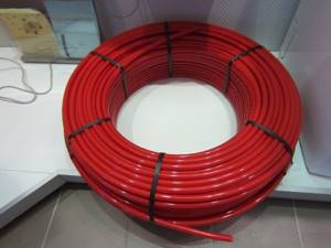
- Pipes made of metal polymer or cross-linked PE with a high pressure level.
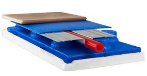
- The parts required for installation are plates intended for heat distribution, mats for fixation, as well as substrates for arranging a thermal insulation layer.
- Mixing module and temperature controller, which are mounted together in the manifold block.
- Temperature conditions can be controlled remotely, which is ensured by automation.
Each of these components is included in the list of basic components of Valtek products.
Cross-linked PE with high pressure, which is used for the production of the pipeline, is recommended by experts for arranging a heated floor system. Today, consumers have access to products with a diameter of 1.6 cm and 2 cm. The connecting elements are systems of press fittings made of brass.
Pipeline layout
Cross-linked PE can also be found in the garden in the form of a hose for watering the lawn. However, unlike a conventional hose, the Valtek polymer piping system is coated with a protective layer of polyvinylethylene (EVOH), which has anti-diffusion properties. Thanks to this, the products do not allow oxygen to pass through, which prevents the formation of corrosion damage to the steel.
There are several installation methods that can be used when installing a water floor system.
The most popular scheme looks like this:
- thermal insulation material that is placed on a concrete base;
- heating elements.
The thermal insulation substrate, which is included in the product package, consists of foamed polyethylene coated with a layer of metallized material.
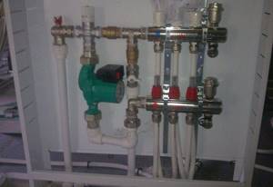
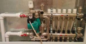
Comb with mixing unit
Polyethylene foam has the following advantages:
- chemical neutrality;
- low level of combustion;
- environmental friendliness;
- high level of thermal insulation;
- sound insulation;
- resistance to moisture.
The collectors, through which the heating system and pipeline are connected, consist of a pair of combs. They serve to introduce coolant into the system and remove it. A shut-off valve (servo-driven or mechanical type) and a flow meter that control the system are installed on the nozzles.
In addition, the device has a mixing unit, which is a three- or two-way valve. One of the pipes of the structure is connected to the heating supply pipe. The second is attached to the outlet pipe. By mixing cold water into the coolant, relying on the readings of the thermal sensor, you can easily adjust the temperature in the entire system.
One of the installation options
As an automatic device, the package includes a servo drive - a device whose operation is based on electronics. Based on indicators from the thermostat, this device adjusts the position of the rod on the valve, thereby controlling the heating power.
In addition, the kit includes a temperature regulator, which is used to control the underfloor heating system. This multifunctional device has a simple system of use. All indicators are reflected on the LCD display, and regulation is carried out using a push-button method.
What is included in the Valtek kit
The water floor kit is compiled depending on the area of the room. Heating calculations are made using a computer program. Depending on the circuit design, the following components are offered:
- VALTEC pipe 26*3 mm; hot liquid passes through it from the boiler to heating devices, radiators or pipelines for the “warm floor” system; condensate enters the boiler through pipes of the same diameter; The pipes are supplied with a crimp connector with a transition to a diameter of 26 mm;
- VALTEC pipe 16*2 mm; intended for the water circuit of the heating system; it is laid on a concrete screed; crimp connector with transition to a pipe with a diameter of 16 mm;
- adapter nipples 1”, 1/2″;
- collector group assembled; the collector is installed for the water circuit; it is connected to the system; there is no need to assemble it from tees, valves and couplings; you only need to connect the water circuit to the finished system;
- the collector is placed in a cabinet specially designed for it;
- check valve 1/2″; prevents the return of liquid through the pipe; protects the system from water hammer;
- ball valves BASE; they are installed on the hot and cold circuit; with their help you can manually turn off the heating for maintenance or repair work;
- circulation pump Wilo Star 25/4; it is placed on the hot circuit;
- three-way thermostatic mixing valve 1”; it mixes hot and cold water; side mixing type;
- The mixer is equipped with a thermal head with a remote sensor; it contains a liquid that is sensitive to a certain temperature regime; hot and cold water are mixed in the mixer chamber; if the water temperature is higher than the set mode, then the liquid in the thermostat expands; the spring-loaded rod is activated; it forces the regulator to turn off the hot water circuit; heating stops; when the temperature in the water circuit decreases, the liquid in the thermostat returns to normal; the rod lowers, the heating circuit turns on again;
Three ways to adjust flow meters
The microclimate in the room and the uniformity of floor heating in different areas depend on the correct adjustment of these devices. In addition, by adjusting flow meters, it is possible to significantly reduce energy losses for heating buildings. And this is very important, given the current cost of electricity and gas.
Inexperienced installers believe that in order for the temperature of the circuits to be the same, the readings of the flow meters must also be at the same level and thus they are adjusted.
Inexperienced installers set everything up “on a ruler”, believing that the flow rate is the same everywhere
This is wrong, if this were actually the case, then why would we need devices that are quite complex from an engineering point of view? Pipes of different lengths must receive different volumes of coolant, only in this case their temperature will be the same. Accordingly, the flow meter readings on each loop are individual.
Flow meter readings on each loop are individual
There are several ways to configure flow meters.
First way
The most correct, fast and accurate. The adjustment must be made taking into account the parameters of the hydraulic resistance of each circuit. For this purpose, VALTEC has developed a special program, which can be used on the website of the official representative. Working with the program is very simple, fill out all the tables with your data and eventually get the resistance of each loop. The only inconvenience is that the results are given in kilograms per second, while the scale on the flow meter is in liters per minute. In order to use the flow meter scale, you need to multiply the obtained data by 60. Set the flow meter scale for each loop according to the obtained values in turn.
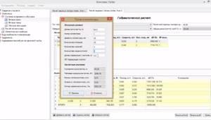
Hydraulic calculation program
Second way
It is used in cases where the cheapest manifold without flow meters with a scale was purchased. Instead, conventional control valves are installed; the flow rate is changed by turning them clockwise or counterclockwise.
Manifold with control valves
It is recommended to install the flow meter on the “return”; they are not adjustable, but do have a scale. Turn the tuning valve and monitor the actual flow rates using the return scale.
Flow meter installation diagram
If for some reason it is impossible to install flow meters on the “return”, then you should use the table supplied with the manifold. It indicates the change in the amount of coolant depending on the number of turns of the control valve. The calculation program gives the values as percentages; you need to find this parameter in the table, so you can find out how many turns to tighten or unscrew the valve. This method is more complicated, but it allows you to save money when purchasing a collector.
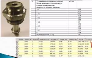
The required values in the table are marked with a tick
Third way
In scientific terms it is called empirical, but in simple terms it is called “by eye”. It requires knowing the actual length of each loop. Adjustment should begin with the longest one.
Loop lengths
Open the valve regulating this loop to maximum. Next, make calculations as a percentage of how much each of the remaining loops differs from the longest one and reduce the clearance of the control valve by the same percentage. This is a preliminary adjustment; later adjustments must be made depending on the actual temperature of the loops. The process may take several days; the floor heating system is very inert and it is impossible to immediately notice a change in its temperature.
The end result is to achieve the same coolant temperature at the return of each loop.
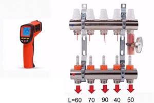
To measure, you can use a clip-on thermometer or a more modern pyrometer
How to set up a mixing unit
Connecting the mixing units is quite simple, so installation can be done with your own hands if you have instructions. The first thing to do is choose a location for the mixing unit.
If the parts of the water floor are connected through flexible pipes, then the mixing unit is rigidly mounted on the wall. The parts of the mixing unit must be freely accessible.
Manifold cabinet and its equipment
It is imperative to take into account the type of material from which the pipes are made. They must withstand the temperature of the incoming coolant. If a water-glycol solution is used, galvanized pipes will not work.
Do not allow liquid to come into contact with live parts of the mixing system.
After installation, the mixing system is connected to the coolant supply and return pipes and pressure, temperature and flow sensors are installed. These elements are either supplied with the unit or assembled independently. After this, the thermal mixer is connected to the outlet pipes of the heating circuit.
Connection diagram for mixing unit
Before connecting the circulation pump, grounding must be done. Optimal pressure loss parameters are ensured using a balancing valve on the bypass. In this case, losses in the check valve are taken into account.
If the heating system is single-pipe, the bypass must always be in the open position. Then the hot water will flow in parts to the radiators. In a two-pipe circuit, the bypass is closed. When the entire structure is assembled, it is connected to the circuits using fittings.
Advantages of Valtek products
Valtec heated floors have many advantages, making them an ideal option for efficiently heating your home.
General form
The advantages of the product are:
- Exceptional reliability, which is achieved through the use of high-quality materials and fastening components in production. The entire package is manufactured directly by the manufacturer itself in entire modules and blocks, so the likelihood of making errors during design and calculation is almost completely eliminated. This indicates efficient and stable operation without the risk of leaks.
- A complete and extensive line of products, which includes components necessary for installation work, materials accompanying installation, elements intended for organizing thermal and waterproofing, as well as for combining with the finishing floor covering. Thanks to this, when installing Valtek products, maximum operational efficiency is ensured.
- The use of a unified system of standards that ensures full compatibility of all available system components and all materials.
Basic nuances and design requirements
The simplest scheme for a warm water floor collector requires that the comb be positioned strictly vertically. Shut-off valves are required in each circuit; they regulate the flow of water between the circuits of adjacent rooms.
In this case, balancing valves are installed in the return ridge.
In a mounted, installed cabinet we install, usually a metal-plastic supply tube (flow from the boiler) and a return tube (discharge of liquid back to the boiler). We install a shut-off valve on both pipes, and only now connect the underfloor heating manifold.
Using fittings, metal-plastic tubes are connected to the side entrances - the contours of the floor.
On the other side of the collector there is also an outlet; you can put a plug on it, or you can use a splitter with a drain valve and an air vent. Since there are two pipes, there are also two manifold combs, and there should be two of all other parts. The circulation pump will ensure cyclic movement of water.
The design of a heated floor water collector has its own operating features:
- the connection diagram for the underfloor heating collector must cover the entire area that needs to be heated;
- the collector group for a heated floor must be made of high-quality material - there is no way to save on this: the slightest leak will require dismantling the screed, which is time-consuming, expensive and troublesome;
- the optimal solution is metal-plastic or polyethylene pipes: they are durable, lightweight, have a smooth inner surface, and are resistant to corrosion and overgrowth;
- the length of the collector circuit should not exceed 100-120 meters - otherwise, either the use of special equipment that provides the necessary water pressure is required, or (the ideal solution) is the creation of several separate “branches”;
- the optimal contour length is 50-60 meters.
Manifold assembly
Assembling a manifold for a heated floor is quite a complex task, and it is best to entrust it to specialists. For your reference, here is an approximate sequence of work.
We unscrew the union nuts, install the system pump on them, and disconnect the threaded adapters. We connect them to the mixing pump assembly of both manifolds. On the opposite side of the collectors we connect the early disconnection threaded adapters and connect the mixing valves. Before installing the 3-way zone valve, check the direction of flow of the heating medium.
Adjustment of the heated floor manifold can be done manually, and if there is a servo drive - automatically. With three-way valves it is more suitable for heating rooms larger than 200 square meters. m. They come complete with a weather-dependent sensor, programmed to independently change the temperature.
In a two-way valve, adjustment occurs using a valve, and if necessary, it will add or remove water. Temperature correction occurs smoothly, and if everything is adjusted correctly, overheating of the floors is eliminated.
The underfloor heating collector must be adjusted according to a balancing table with two parameters: heating load and circuit length. The speed and circuit number are related to the “closed” position of the balancing valve.
- Remove the valve cap;
- Turn the valve all the way;
- Determine the number of revolutions for this circuit;
- Turn the valve to the indicated number;
- Everyone else is set up the same way.
Prices for specialists' work
Installation of a heated floor collector involves planning, assembly, testing, and adjustment. There is a lot of work, but if you set a goal, it is better to know a number of important points right away.
Purchasing a manifold for a water heated floor, pipe fasteners, mesh and fasteners, a cabinet, a mixing unit (if not in the boiler room), connecting fittings along with installation and piping of the manifold for a Valtek heated floor will cost you 30,000 rubles.
The Valtec underfloor heating manifold, by the way, is the most successful solution to the problem - this product has been tested for years and by hundreds, thousands of customers.
On average, the price of a collector for heated floors is from 3,000 rubles. But you shouldn’t save money; we advise you to buy a manifold for heated floors, the cost of which is from 5,000 rubles. It is more reliable, lasts longer, and can withstand high water pressure if the pressure in the water supply system is too high.
Delivery and work are not taken into account in the total cost of all costs, since they vary depending on the company, store and service.
Valtec underfloor heating collector for 2-4 circuits (20-60 sq.m.)
Specification
- 1 – Mixing valve MIX 03 3/4” – 1 piece;
- 2 – Nipple adapter 1-3/4” (VTr.580.N.0605) – 2 pcs;
- 3 – nipple 3/4” (VTr.582.N.0005) – 1 pc.;
- 4 – tee 3/4” internal-internal-internal. (VTr.130.N.0005) – 1 piece;
- 5 – elbow 3/4” external-external. (VTr.093.N.0005) – 1 piece;
- 6 – American 3/4” (VTr.341.N.0005) – 1 piece;
- 7 – circulation pump with 1” union nuts;
- 8 – ball valve 3/4” internal-internal. (VT.217.N.05) – 2 pcs;
- 9 – manifold 3/4-1/2” external. (VTc.500.N.0502) – 2 pcs;
- 10 – collector connector 16-1/2” (VTc.710.N.1604) – 4 pcs;
- 11 – connector with ext. threads 20-3/4” (VTm.302.N.002005) – 1 piece;
- 12 – connector with external threads 20-3/4” (VTm.301.N.002005) – 1 piece;
- 13 – collector tee (VTc.530.N.0500) – 2 pcs;
- 14 – automatic air vent 3/8” (VT.502) – 2 pcs;
- 15 – drainage valve 1/2” (VT.430) – 2 pcs;
Connection
Using connectors (10), a metal-plastic underfloor heating pipe with a diameter of 16x2 is connected. The high-temperature circuit supply (boiler supply) is connected to terminal 16, and the boiler return is connected to terminal 17.
Valtec underfloor heating manifold with manual adjustment for 2 circuits. For normal operation, the loops must be approximately equal in length. It is advisable to install American taps at the inlet and outlet of the heating system 16, 17.
If 3 or 4 circuits are used in the above heated floor mixing unit, then two manifolds (9) are replaced with one adjustable manifold (VTc.560n) and one manifold with ball valves (VTc.580n).
Pipes for the system
Valtek warm water floors are equipped with pipes produced by the same name. Metal-polymer pipes are used that can withstand multiple temperature changes without changing their structure.
The inner and outer layers of the Valtec pipe are made of cross-linked polyethylene, and between them there is a layer of aluminum foil. This design prevents air from entering the pipe and also ensures that the pipe maintains its constant geometry.
All layers are connected to each other with an adhesive composition.
Main characteristics of Valtec pipes for underfloor heating:
- The active service life is more than 50 years.
- The maximum operating temperature of the coolant is 95 degrees. For a short time, when pumping water, it is allowed to increase its temperature to 130 degrees.
- Valtec pipes have a minimum coefficient of thermal linear elongation.
- The surface of the pipes is resistant to cement.
The price of Valtek underfloor heating largely depends on the price of the pipes used. So, a Valtec pipe with a diameter of 16 x 2 mm costs about $0.5. A 32 x 3 mm pipe will cost about three times as much.
System advantages
Valtek underfloor heating systems have a number of advantages.
We list the main ones:
- Any type of fuel can serve as fuel for the boiler - wood, coal, liquid fuel, coke, gas.
- Warm floor Valtek can be used with almost any floor covering.
- Uniform heat distribution is guaranteed, unlike radiator heating, when warm air rises upward near the wall. Due to this, dust does not circulate in the room.
- Valtec water heated floors help reduce heating costs. For a private home this is very important, since heating is individual.
- If we compare water and electric floors, we can note one important feature. When using a Valtec floor, no electromagnetic fields are generated.
- Valtec heated floors are more economical compared to electrically heated floors.
- Pipes for the collector are produced using a special proprietary technology, the purpose of which is to strengthen the collector as much as possible. Moreover, the strengthening is carried out both of the structure itself and of the internal walls, which are protected from corrosion and the creation of blockages.
The conclusion is clear. Water heated floors from Valtec are an ideal solution for additional heating of a private home.
Since the brand is quite popular, you can find a lot of reviews about it.
Evdokimov S., 46 years old, Kaliningrad:
The called specialist quickly found the problem and replaced the sensor (as it turned out, it was faulty and showed an incorrect, low temperature, due to which the system also reacted incorrectly). Ruslan, 39 years old, Ryazan:
Liquid system underfloor heating
Underfloor water heating is considered more economical than heating a house using radiators. Warm air that comes from the floor rises from bottom to top. This creates a comfortable microclimate in the room. Cooling down, the air flow rushes to the walls and returns again to the floor or leaves the room due to ventilation.
On the floor and at the level of an adult’s head, the air warms up to a comfortable temperature. The temperature regime is programmed for each room separately or for the entire system as a whole.
With radiator heating, a warm flow of air immediately rushes upward from the appliances to the ceiling. Cooling down, it begins to sink down towards the floor. In this case, the floor covering remains cold and the ceiling is warm, which is not always convenient for household members. In addition, radiators may be incompatible with the design of the room. With water heating, all pipes are hidden under the floor. How does the “warm floor” system work?
- Initially, you will need to organize a heating source, stove or boiler. For a wood or liquid fuel stove, it is recommended to equip a boiler room.
- A separate room is not provided for an electric or gas boiler of low power. Boilers are installed on the floor of the house or mounted on the walls.
- Inside the furnace or boiler there is a water circuit, a heat exchanger. It is initially filled with water.
- The heat exchanger heats up in the firebox, forcing water to circulate through the pipeline.
- Hot liquid enters the pipes.
- Giving off heat, it returns back to the boiler.
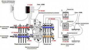
Automatic control is connected to the system in order to be able to regulate the operating mode of the heating equipment. Connecting units are installed in the circuit, which allow you to drain excess liquid into a storage tank, turn off the floor heating as needed, and switch the heating to a radiator system.