Pros of the Valtec system
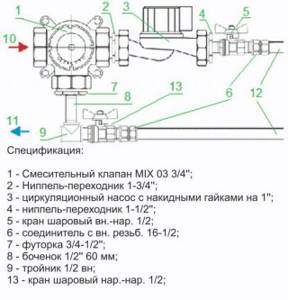
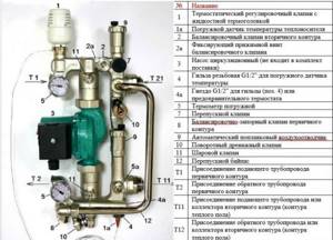
Specification of a Valtec mixing unit for underfloor heating
Before starting installation and selecting a mixing unit for Valtec underfloor heating, it is necessary to analyze the advantages of this type of water circuit.
- Thanks to high-quality materials and durable fasteners, reliable operation is ensured.
- Developed in the form of modules, the components fit together precisely, eliminating the risk of leaks.
- The manufacturer has provided for the production of related materials necessary for thermal and waterproofing equipment.
Calculation instructions
In order to correctly develop a project for laying a heated floor, you will need a preliminary calculation of the main indicators, focusing on their average values.
Do-it-yourself installation of water heated floors
Various factors have to be taken into account, including the role of the water floor as the main type of heating or its use as an additional heat source. Since detailed calculations for independent implementation are a complex process, in practice average parameters are used.
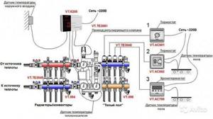
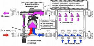
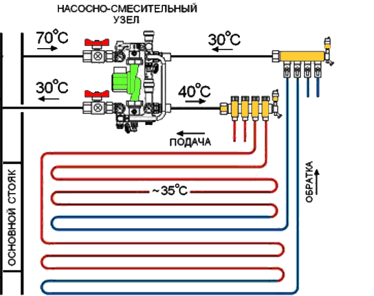
Valtec mixing unit connection diagram
- The rated power has limits of 90 - 150 W/m2. Higher values are selected for rooms with high humidity levels.
- When calculating the laying step, you need to focus on the range of 15–30 cm. The specific heating power is in inverse proportion to this indicator. That is, the larger the step, the less power.
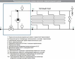
Thermomechanical diagram of a pumping and mixing unit - Despite the fact that with a large diameter of pipes, a larger amount of coolant passes through them, the limiter of this indicator is the thickness of the screed, which is not recommended to be too large, so as not to create excessive load on the floor. Therefore, Valtec pipes are taken into account, made of modern cross-linked polyethylene with an anti-diffusion coating, with a diameter of 16 to 20 mm, and Valtec press fittings are used as connecting parts.
Once the key parameters have been determined, a diagram can be developed in which the most efficient pipe laying is determined on an exact scale. After this, their total length is calculated. At the same time, it is thought through where the pumping and mixing unit and control elements will be located.
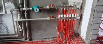
What are manifolds for heated floors and why are they needed?
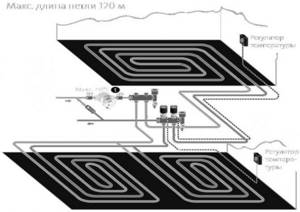
Water floor heating requires laying a large number of pipes. Since the pipes are used with a small diameter, they have high hydraulic resistance. So that the boiler can “push through” the heated floor and so that the floor is heated more or less evenly, the length of one pipe is limited. Theoretically, the maximum length of one circuit (pipe) is 120 meters. In practice, it is recommended to do no more than 70-90 meters. Even at 90 meters, until the water reaches the end of the pipe, it cools down significantly.
A Valtec manifold is needed to connect the circuits to the supply and return pipelines
So, there can be several such circuits even in one room. What if heating is done in several rooms? What if there are also several floors? There may be a dozen contours or even more. It all depends on the heating area. All these pipes cannot be connected directly to the boiler. This is why collectors are needed - to connect underfloor heating circuits. In the simplest version, the collector consists of two pipes - supply and return - with bends welded to them. The heated floor circuits are connected to these outlets. There may still be shut-off valves in place so that the water supply in a particular loop can be shut off.
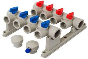
Not Valtek, but one of the simplest collectors. Bends and shut-off valves only
But supplying and collecting coolant are not all the functions that a collector usually performs. The length of the circuits connected to the collector may vary significantly. If the collector is simply pipe branches, the shorter and longer ones receive the same amount of coolant. This results in the floor being too hot in some places and too cold in others. To be able to regulate the temperature (indirectly), flow meters or control valves are installed. They allow you to manually or automatically balance the flows so that the floor temperature in all zones is almost the same. With their help, you can make a specific area warmer. But not because it happened so, but because I want it that way.
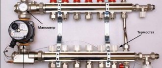
Key characteristics of the mixing unit
In order for the installed water circuit to function effectively, it is necessary to correctly calculate the entire system and correctly install the mixing unit for the Valtec heated floor in accordance with the provisions reflected in the instructions included with the kit.
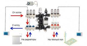
Connection diagram of the mixing unit to different types of heating
Parameters of the pumping and mixing unit:
- the cross-section of the pipes is ¾ inch, the collectors are 1 inch;
- the design contains 12 pipes;
- the pumping system is 18 cm long;
- the temperature of the heated water in the system is maintained up to 90°C;
- maximum pressure value – 10 bar;
- throughput – 2.75 m3/h.
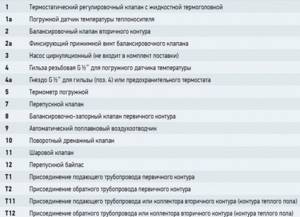
Specification of Valtec pumping and mixing unit
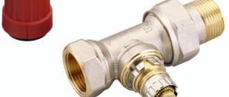
The pipes have an external thread with a Eurocone connection.
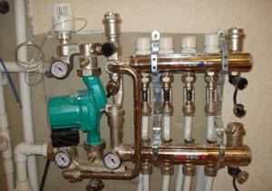
Pumping and mixing unit for heated floors
[ads-mob-1][ads-pc-1]
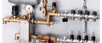
Functionality
The main purpose of the pumping and mixing unit is to stabilize the temperature of the coolant when entering the water circuit by using water from the return line for mixing. This ensures optimal functioning of the heated floor without overheating.
The Combi unit design includes the following service elements:
- drain valves;
- air vents;
- thermometers.
Operating principle of the Combi unit
The following organs are used to adjust the unit:
It is permissible to connect an unlimited number of heated floor branches with a total power of no more than 20 kW to the VALTEC COMBIMIX node
- a balancing valve on the secondary circuit, which ensures mixing in the required proportion of coolants from the supply and return pipelines to ensure the standard temperature;
- balancing shut-off valve on the primary circuit, responsible for supplying the required amount of hot water to the unit. It allows you to completely shut off the flow if necessary;
- a bypass valve that allows you to open an additional bypass to ensure the pump operates in a situation where all control valves are closed.
The connection diagram has been developed taking into account the possibility of connecting to the pumping and mixing unit the required number of floor heating branches with a total water consumption not exceeding 1.7 m3/h. The calculation shows that a similar amount of coolant flow with a temperature difference of 5°C corresponds to a power of 10 kW.
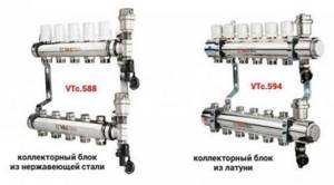
In the case of connecting several branches to the mixing unit, it is advisable to select collector blocks from the Valtec line with the designation VTc.594, as well as VTc.596.
Installation algorithm
After the preliminary calculation of all components has been completed, the actual installation of the heated floor begins, which involves going through several stages.
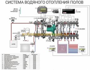
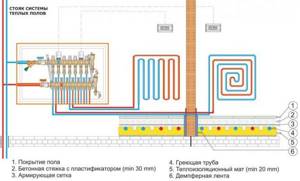
Scheme of water floor heating
- Installation at a pre-selected location of the manifold cabinet. It contains a module consisting of a collector block and a pumping and mixing unit with ball valves, through which the connection to the high-temperature circuit will be made.
- Preparing the floor plane. If there are significant irregularities, measures are taken to eliminate them. The most effective option is a rough screed.
Connection diagram of the pumping and mixing unit to the heated floor - Fixation around the perimeter of a damper tape, which serves as an element that compensates for the possible expansion of the screed that occurs when it is heated. It is attached to the walls so that after finishing the excess remains, which is cut off before installing the plinth.
- Thermal insulation equipment by laying polystyrene foam boards with mounting bosses on a leveled floor, under which waterproofing is laid if necessary.
- A previously developed diagram serves as a guide for the subsequent layout of pipes.
How to assemble a collector?
The Valtec distribution block is manufactured assembled. Flow meters are already installed on the hot tube. There are thermal heads on the cold line, but the product may only have outputs for attaching temperature control devices. They are protected by plastic caps. The manufacturer gives you the opportunity to choose which automation to install: thermal head, servo drive.
Some small elements need to be connected to the collector group:
- On the right, shut-off valves are connected to the tubes. There are 2 of them in the set.
- A float device is connected to the valves to remove air.
- Opposite the air vents, drain valves are connected to the underside of the tubes.
- The ends of the comb are closed with plugs.
We recommend: How to connect a heated floor?
A circulation pump and a three-way or two-way valve are separately connected to the comb. These devices must be purchased separately. They are connected on the left to the tube into which the cold coolant flows. Use brass threaded fittings.
The cold and hot circuits are removed from metal pipes that are connected to the boiler or furnace. They are connected via a bypass at the outlet of the collector group. A circulation pump with a temperature sensor is installed between the circuits.
The rotameter is adjusted when testing the heating system. The protective sleeve must be removed from the device. Using the red ring, the upper bushing, set the rotameter to zero.
Next, using the same bushing, install the valve on the o for large rooms, on the o for small rooms. To fix the rotameter parameters, turn the lower ring to the right until it stops.
Return the protective cap to its original place. The rotameter may not have a locking ring. In this case, the pipeline fill indicator is set without fixing. Valve operation must be checked regularly.
Valtek collectors for heated floors are installed with a liquid heating system. The coolant can be water, antifreeze, glycol fillers that do not freeze at low temperatures. If the heating system is not used, then the coolant does not need to be drained.
The number of circuits on the distribution block is 3-12 pcs. If necessary, additional equipment can be connected to them to increase the flow capacity of the coolant to all rooms in the house.
The comb is mounted on the wall or placed in a manifold cabinet. The manufacturer provides a 10-year warranty on the equipment. Service centers are located in St. Petersburg and Moscow. The block will last more than 50 years.
If necessary, the rotameter or thermal head can be replaced without turning off the heating system. When using a programmable thermostat, the operation of the heated floor control unit can be carried out through electronic gadgets.
We recommend: How to assemble a manifold for underfloor heating?
YouTube responded with an error: The request cannot be completed because you have exceeded your quota.
- Related Posts
- What is a warm floor National Comfort?
- Do you need warm floors in your home?
- How can you make warm floors?
- Features of the “combined heating: warm floor and radiators” system
- How is the mesh for underfloor heating installed?
- How to make a warm floor from central heating?
Settings
To connect pipes to distribution manifolds, a pipe cutter is used to cut the required length, a calibrator, a chamfer and a compression fitting. It is difficult to carry out detailed calculations at home, so be sure to study the instructions, which detail the settings of the pumping and mixing unit in a certain sequence.
- The thermal head is removed.
- For a balancing valve on the secondary circuit, the capacity is calculated using the formula.
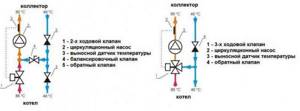
Two mixing unit options
kνb = kνt {[(t1 – t12) / (t11 – t12)] – 1},
where kνt – coefficient = 0.9 valve capacity;
t1 – supply water temperature of the primary circuit, °C;
t11 – temperature of the secondary circuit at the coolant supply, °C;
t12 – return pipeline water temperature, °C.
The calculated kνb value must be set on the valve.
- Setting the desired operating mode of the bypass valve when setting the maximum pressure difference to 0.6 bar.
- In order for the heated floor to function effectively, the required pump speed is adjusted. To do this, it is necessary to determine the value of the coolant flow rate in the secondary circuit system, as well as the pressure loss that appears in the circuits located after the unit.
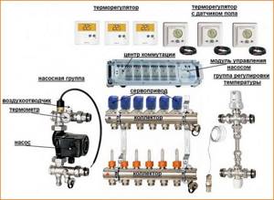
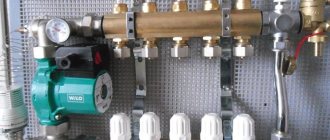
Equipment for Valtec mixing unit
Flow rate G2 (kg/s) is determined by the formula:
G2 = Q / [4187 • (t11 – t12)],
where Q is the total thermal power of the water circuit connected to the mixing unit, J/s;
4187 [J/(kg•°С)] – heat capacity of water.
To calculate pressure losses, a special hydraulic calculation program is used. To determine the pump speed, which is set using a switch, according to the calculated indicators, a nomogram is used, which is in the instructions attached to the heated floor design.
Connection diagram for heated floor circuits
- Operations are being performed to adjust the balancing valve on the primary circuit.
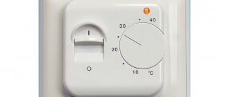
- The thermostat sets the temperature required for comfortable heating.
- A trial run of the system is being carried out.
If there are no leaks, all that remains is to make a concrete screed, and after it has completely hardened, lay the flooring. [ads-pc-2][ads-mob-2]
Features of setting up a Valtec manifold without flow meters
If the manifold is not equipped with flow meters, but only with valves, you will have to set the flow rate by touch. This is not figurative, but literally. Knowing the length of each circuit, we open the flow to the maximum on the longest one. We screw the rest approximately. You can count the number of valve revolutions and focus on them.
Manifold for underfloor heating without flow meters
Next, we turn on the heating and wait until the floor warms up. If you have a thermometer, measure the floor temperature in the operating area of each circuit. There is no thermometer - we feel and compare sensations. Based on the results, we adjust the position of the valves and wait again for several hours. We continue this way until we are satisfied with the result. In principle, a Valtec manifold with valves without a flow meter is not that difficult to configure.
Evaluating collector settings based on return temperature
This check is based on the fact that with a correctly adjusted flow rate, the return temperature on all circuits should be the same. To set up or check this type, you need special thermometers. They are installed on the return pipeline between the manifold inlet and the pipe.
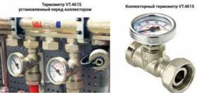
You can adjust the collector using a return thermometer
The temperature of the longest circuit is taken as a reference - all the others are adjusted to it. Only the adjustment results will need to be corrected after a few hours. When the floor heated by adjustable circuits warms up or cools down (depending on the adjustment) and the temperature in the return pipe changes again. It will take several such adjustments until the difference becomes insignificant.
Water-based types of heated floors continue to improve, remaining popular among consumers. One of the recognized leaders is the Italian company Valtec.
VALTEC mixing unit for heated floors