A thermal head for underfloor heating is installed in the heating system so that the temperature in the room is maintained at a given level.
A comfortable temperature is considered to be 20°C at a height of 1.5 - 2 m, with a floor covering temperature of 22 - 24°C. The placement of the heating element along the entire horizontal plane of the floors allows for uniform heating of the air in the room.
Purpose of a thermostatic valve and its scope
The thermostatic mixing valve is used in underfloor heating with circulating water inside.
The heating temperature of the coolant for conventional batteries is much higher than that required for water floors. Overheating of the concrete screed will worsen the microclimate and lead to damage to the floor finishing material. A thermostatic mixing valve for underfloor heating will help solve this problem. Using it, you can create an independent circuit with the desired temperature, or power a heated floor from central heating.
The thermostatic valve allows you to solve the following problems:
A mixing tap is not needed if:
How does automation work?
A thermostatic three-way valve for underfloor heating is connected in front of the manifold. A certain temperature heating mode is set on the sensor. The device starts working when the parameters are changed.
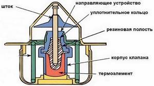
- The device consists of a semiconductor, which has the temperature of the coolant entering the line. Energy is transferred to the thermostat fluid.
- As the heat increases, the liquid expands and puts pressure on the rod, which lowers.
- In this case, the outlet from the hot pipe is closed and the outlet from the return circuit is opened.
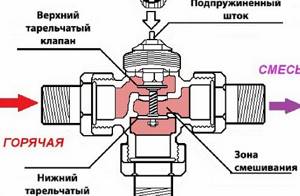
- The cooled coolant enters the three-way mixer chamber, where it is combined with hot water from the boiler. The mixing process can take place according to a T-shaped pattern: hot and cold coolant flow enters the thermostatic mixing valve symmetrically from both sides. The liquid exits into the main line at an angle of 900. With an L-shaped design, hot water enters the mixing chamber from the side.
- The coolant temperature decreases. It enters the floor line cooled. The heating mode strives to reach the set norm.
- As the temperature drops, the liquid in the thermostat contracts. The spring-loaded rod straightens, closing the outlet of cold water that flows through the return pipe. Hot coolant again enters the main line.
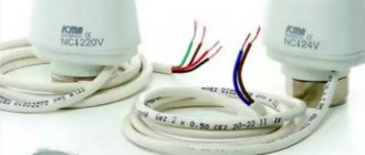
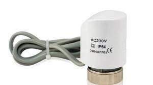
When using servo drives, a device that operates from the network is connected to the mixing valve for heated floors. The sensor heats up and closes the electrical circuit. The plate is heated, which in turn transfers heat to the thermal fluid. It expands, pressing on the rod, which makes the poppet valves work.
When using a servo drive, the heating system changes operating mode within 3 minutes. If you use a thermal head as an automatic device, it will take up to 15 minutes to heat the liquid in the thermostat.
The operating principle of a two-way valve for underfloor heating is somewhat different. When the temperature in the main increases, the thermostat causes poppet valves or a ball device to operate, which completely blocks the outlet for hot water. The cooled coolant from the return pipe returns to the floor circuit.
When the temperature decreases, the valve opens hot water and closes the return flow. There is no mixing of the liquid. The principle of operation of a two-way thermostatic valve for underfloor heating is identical to manual switching of valves, but the system operates in automatic mode.
Equipment for automatic control of the heating mode can be installed in a single-circuit or double-circuit heating system. This is convenient when using various types of heating, radiator and floor. The mixer is connected before the circulation pump. I recommend installing a water filter first. When connecting, use the threaded installation method.
Types and their structure
In a thermostatic distribution valve installed on a heated floor, the heated water is mixed with cooled water from the return pipe. This process is continuous as long as the heating is on.
There are two-way and three-way mixing valves for underfloor heating. They also differ in the method of mixing and the direction of flow.
Two-way
The two-way thermostatic valve is an improved manual type model. It can be hydraulic, pneumatic or electrically driven.
The design is simple, but capable of effectively regulating the temperature level of the coolant in automatic mode. The device is mounted in the heating system, instead of a manual valve.
Disadvantages - the possibility of installing it on pipelines with a small size. If you use this faucet when installing heating in a room with a large area, the thermostat will function intermittently. A two-way valve is more often used if heated floors act as additional heating.
The valve device is a brass or bronze body, with one or two seats. A double-seated valve can completely shut off the flow of water.
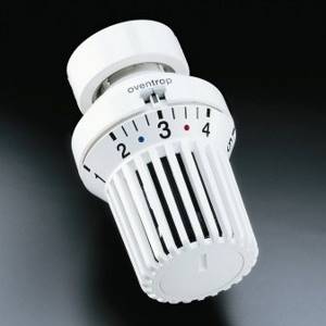
The device is equipped with a thermostatic head with a scale. The head position can be changed manually or automatically. Manual models are simple and inexpensive. More modern devices work automatically.
The two-way valve operates according to the following principle - the coolant from the return line is again supplied to the floor pipes, but before this, a device is activated that opens the supply of heated water. The two flows are mixed inside the housing to the desired degree, then the temperature sensor is triggered and the shutter automatically closes the hole with the hot coolant.
The valve consists of a plunger and a seat. The plunger has a disc, needle and rod shape. It is located perpendicular to the movement of the fluid.
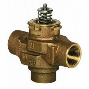
Three-way valve
The operating principle of a three-way thermostatic valve for floor heating is that cooled water from the return line is added to the hot water coming from the boiler.
The valve is designed for heating systems that are installed in large rooms. They have the same advantages as two-way valves. Particularly worth noting is the ease of adjusting the water temperature for heated floors.
But this thermostatic valve also has a minus - if the thermostat is triggered, the valve opens completely, thereby allowing hot coolant to enter the circuits. And this can cause overheating of the heating system, and even rupture of pipes. In addition, it has a lower flow capacity than a two-way valve.
Three-way thermostatic mixing valves are available in brass and bronze. They are equipped with a thermal head or thermostat, and can have an electric drive or a servo drive. The design is a faucet with two inlets and an outlet. Inside the case there is a mixing chamber, on which there is a thermostat with a regulator on which there is a digital panel. A thermal valve is connected in front of the manifold.
Operating principle of three-way thermostatic valve:
It should be said that when the device is turned on, the water flow voltage does not change. This leads to a uniform change in the temperature of the liquid supplied to the line.
By mixing method
Mixing taps for heated floors, depending on the mixing method, are:
How to choose
The thermostat is selected according to the operating characteristics of the heating system. The device must:
- Withstand pressure in the range of 16–40 bar and temperatures up to 200 °C.
- Be made of corrosion-resistant materials that are resistant to mechanical stress.
- Match the diameter with the size of the pipeline.
- Match the thread parameters on the pipe.
Popular manufacturers
Thermostats manufactured by the following companies are considered the most reliable and durable:
Danfoss (Denmark). Devices from this manufacturer, despite their fairly low price, have an improved design. They are equipped with a flow stabilizer, so they operate silently. They do not become clogged when working with any contaminated coolant, since their rod stroke is 1.5 times greater, and the performance adjustment window has a larger cross-section.
Oventrop (Germany). The variety of standard sizes of thermostatic fittings from Oventrop allows you to choose the ideal model for any engineering system. Excellent regulating qualities, high product reliability are combined with an aesthetic appearance.
Luxor (Italy). Luxor thermostats are suitable for heating systems where the coolant is hot water. They are equipped with a thermostatic spindle that allows pre-setting of the flow.
Installation diagram
Water heated floors today are a common system for heating a home; different schemes are used for its arrangement.
Heated floor equipment with three-way valve
Installation of underfloor heating with the installation of a three-way thermostatic valve is suitable for mixed heating systems. Radiator (water temperature 80 degrees) and underfloor heating (the liquid should not heat above 50 degrees).
The question arises - how to cool the water from 80 to 50 degrees. This is what the three-way thermostatic valve is designed for. It is attached to the supply pipe, and a circulation pump is connected behind it.
The working process is as follows:
The disadvantage of this method is the inability to dose the waste water mixture, and this leads to the entry of overheated or underheated coolant into the main line. Plus - easy installation and low price of equipment.
There are two installation schemes for a water heating floor with a three-way thermostatic valve; they differ in the direction of flow:
Both valves are compact and widely used in warm hydrofloors.
Working with Manifold Flow Meters
Hydraulic balancing of underfloor heating loops involves normalizing the flow in each coil. Depending on the length, different amounts of incoming coolant may be required so that when passing through the loop it cools exactly to the calculated value. The required flow is quantitatively determined as the ratio of the thermal load on the loop to the product of the heat capacity of water or other coolant and the temperature difference in the supply and return: G = Q / s * (t1 - t2).
You can often find recommendations to determine the coolant flow according to the performance of the circulation pump, that is, to divide its supply in proportion to the ratio of the lengths of the loops. Such advice should be avoided: in addition to the fact that it is quite difficult to calculate the length of each coil, one of the most important rules is violated - choosing equipment parameters based on the needs of the system, and not vice versa. Attempts to distribute flow in the described manner almost always lead to the fact that the flow in the loops differs significantly from the calculated values, which makes further adjustment of the system impossible.
Adjusting the flow with flow meters is quite simple. In some models, the throughput is changed by turning the body, in others - by rotating the rod with a special key. The scale on the flow meter body indicates the flow rate in liters per minute; you just need to set the float to the appropriate position.
Almost always, when the capacity of one flow meter changes, the flow rate in the remaining loops changes, so the adjustment is carried out several times, sequentially calibrating each outlet. If such changes are particularly pronounced, this indicates a lack of capacity of the control valves through which the collector is connected, or that the performance of the circulation pump is too low.
Alternative ways to connect heated floors
There are other options for connecting warm water floors:
If the heated floor is equipped according to this scheme, then it is better to install a condensing boiler, since it is able to operate at full capacity in low temperature mode. A conventional boiler operating at low temperatures will cause heat exchanger failure. When using a solid fuel boiler, a buffer exchanger is required to regulate the temperature.
All pumping and mixing units have a balancing valve; it dispenses cooled liquid. Thus, it is possible to obtain the strictly required water temperature for the reproductive system at the outlet of the equipment, which increases its efficiency.
There are different models of pumping and mixing units, they are equipped with: a bypass, which has a bypass valve, a balancing valve or ball valves, they are located at the edges of the pump.
When planning to install a warm water floor at home, you should think through all the design elements in advance. And most importantly, how the required temperature of the coolant in the heating system will be achieved. Of course, a pumping and mixing unit is a more advanced device, but it costs more, and not everyone can install it themselves.
An excellent option is a thermostatic valve. It is inexpensive, its connection is simple, and at the same time, it copes perfectly with the function of adjusting and controlling the water temperature.
Source
Criteria for choosing thermostats for heated floors
In order to make your heating system as efficient and controllable as possible, you should not neglect expensive device models. In most cases, the choice of device is influenced by living conditions and the intensity of use of heating equipment.
It should be said right away. Mechanical thermostatic valves are simple and convenient. They are usually used in residential areas where people are constantly present. Even in a room where children are, installing such devices is not prohibited. The devices have appropriate protection.
In cases where there is often no one at home, and the need for heating exists constantly, the best option would be to use a programmable thermostat. By setting the necessary time and temperature parameters in advance, you will organize automatic operation of the heated floors. For those who are planning to install heated floors at home, when purchasing a thermostatic regulator, a number of nuances should be taken into account:
- when relying on automated devices, it is necessary to have a constant voltage in the home electrical network;
- the permissible temperature threshold for the thermostat is 60C;
- Installation of devices is carried out in two versions, using a panel installation or wall mounting. The panel mounting option is used in large premises. The wall-mounted version is mounted next to an outlet or electrical panel and is more suitable for working in small spaces.
Functional role of the thermal head in the floor heating control system
How nice it is to walk on a heated floor in winter and not be afraid of freezing - this type of heating is especially important in a house where children are growing up. Warm floors are a convenient alternative to classic or electric heating in the house. Just recently it was impossible to imagine something like this, but technology quickly reached this point, because today such systems are available to every person.
Types of thermal heads
Depending on the substance in the bellows, thermal heads can be gas, liquid or paraffin based. Liquid - inertial, working slower, taking a long time to heat up and cool down, but the most accurate.
Gas ones have a large error and are vulnerable to drafts. Inside the head there is a mnemonic diagram on which zones with temperatures are marked.
Electronic devices are controlled by a display, and an electric drive presses on the rod. Such equipment is more expensive, but is highly accurate.
The thermostat contacts the surface in several ways, so the thermal head can be a surface-mounted one, with an air sensor, or an immersion type.
The thermostat heats up at the place of fixation, and the overhead and air thermostats are connected to the sensor by a sealed capillary-type tube. The bellows expands from the heating of a canister located remotely - such units are used in heated floors.
The principle of operation of the thermal head
Proper mixing of hot and cold water should ideally correspond to the readings of the sensor.
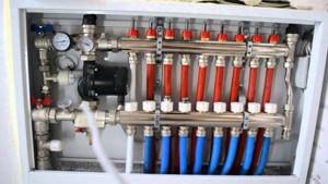
There are standards that include the degree of heating inside the system up to 90 degrees, while the floor itself should not be higher than 40 degrees. The optimal recommended temperature is 22 degrees. Proper operation of the thermal head is the key to uninterrupted operation of the entire system.
Choosing a reliable thermostat for a water floor
Choosing a boiler for a warm water floor, characteristics of types, scope of application
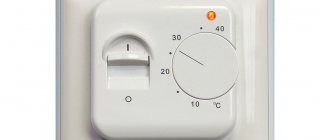
Thermoregulator (other names - thermostat, heated floor controller) is equipment that is used to maintain the user-specified water floor temperature in the heating circuit.
Together with the thermostat, temperature sensors are usually used - air and the floor itself. The supply of coolant (water, antifreeze, ethylene glycol) is regulated by a special device - a servo drive. in this article we will tell you how to choose the best option.
Types and their differences
The choice of thermostats on the heating equipment market today is quite wide.
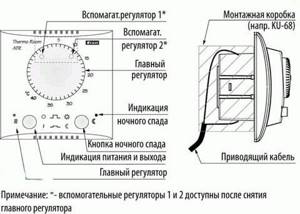
Electromechanical diagram
Depending on the type of automation, these devices can be:
- Mechanical
- Remote (various control panels, including touch)
- Electronic
- Electronic - programmable
Based on functionality, thermostats are divided into:
- T. with air temperature indicator
- T. with water floor temperature indicator
- T. with both sensors
The power of a water heated floor can reach 600, 2000, 3000 and more than 3000 W.
The thermostat turns on and off automatically, depending on the readings of the air and floor temperature sensors. These devices also differ in installation for indoor and outdoor.
Details about the operation of the device
A mechanical thermostat is the cheapest and easiest to use. Simplicity in this case is its main advantage. The temperature of the water heated floor is adjusted by rotating the rotary wheel.
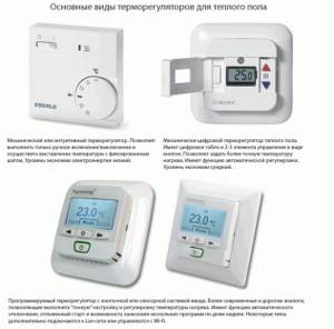
The regulator protects the room from overheating, as it turns the heating system on and off automatically. The disadvantage is the inability to program the equipment, so the temperature has to be changed manually several times a day.
The electronic regulator is equipped with a digital display and several control buttons, which makes it a little more comfortable than a mechanical thermostat. There are water and air temperature sensors. With a programmable thermostat, you can set the temperature for a day or a week.
The remote-controlled thermostat programs up to 9 different modes, also displaying on the display the amount of energy consumed for different periods of time. A device such as a thermostat will help you monitor the temperature of the air and water-heated floor, as well as save on energy consumption.
Useful tips
The choice of thermostat for heated floors directly depends on your living conditions, as well as on your goals and desires. Mechanical appliances are convenient for those who spend most of their time at home. They are also suitable for those who have small children, because... equipped with the necessary protection.
If you are constantly at work and there is no need for constant heating of the room, then it is better to use a programmable controller that will turn on and off at the time you need. The most comfortable devices are those with weekly operating cycles - they can be perfectly adjusted to your rhythm of life.
In addition, when buying a thermostat, it is important to remember the following:
- If you decide to use an automated thermostat, then you need to set the maximum voltage of the electrical network - having reached a certain point, the system will turn off itself and begin to cool down
- The maximum possible temperature for heating rooms using water-heated floors is + 60*C
- Installation of this device can be panel and wall; the former are used for heating large rooms, they are more expensive, in addition, a separate shield is required for operation; wall-mounted – mounted next to a power source and intended for home use
- If you do not have special skills, then you should not install the regulator yourself - entrust this task to the hands of professionals;
The choice of thermostats is quite wide. Today, these devices are represented on the heating equipment market by such companies as Thermoland, Devi, Raychem, I-WARM, etc.
The price depends on functionality, dimensions and temperature range. So, with the Thermoland TRL-02 regulator, the temperature will fluctuate from 0 °C to +57 °C, its cost is approximately 50 USD, while the Devireg 850 (from −10 °C to +40 °C) will cost at 550 USD
Conclusion
A thermostat is equipment that regulates the temperature of the coolant in the underfloor heating circuit.
This device is very important for the proper operation of the heating system. By learning how to use a thermostat, you will fill your home with comfort and coziness.
May your home always be warm!
Advantages and disadvantages
Such heating has a number of undeniable advantages, among which cheap operation comes first. A warm floor heats the entire room compared to mounted electric radiators, during the operation of which the heated air rises, but the floor, in fact, remains cold.
Such a heating device does not disturb the balance of air humidity in the room, which is also an undeniable advantage.
Warm floors do not have any critical disadvantages, but some nuances are still worth taking into account. The complexity of installation places serious demands on the preparation of the area. A pipeline leak during operation can be a serious inconvenience, because in case of repairs the floor covering will have to be opened. Such a floor cannot be installed in hard-to-reach places (on stairs or in small rooms), which requires additional heating equipment.
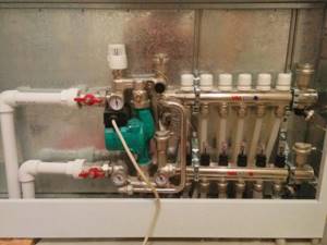
Thermal valve for heating system
The thermal head is installed strictly horizontally and contains a specific meter that transmits signals to the electric drive about the closing or opening of the valve. The hydraulic valve has three coolant passages, two of which are used to supply water to the mixer, and the third is responsible for supplying the total flow to the pipeline.
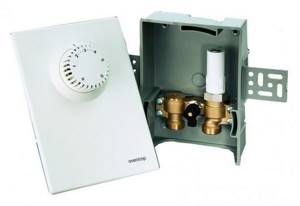
The block is made of stainless steel, since the device has to work in a constantly humid environment and there is a risk of corrosion. In operating mode, the floors sensitively respond to changes in heat in the room, automatically adjusting the heating of the circulating fluid inside.
System Features
The thermal head, which is installed on the valve, is responsible for stable heating of the floor temperature.
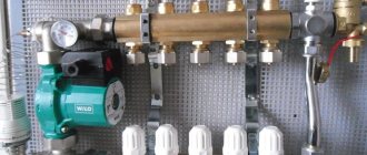
A typical system includes pipes, thermal insulation, thermal head with sensor, fasteners, welt tape, accessories to minimize seams, manifolds with fittings and sometimes an additional pump group package. The functioning of the heated floor is carried out in the mixing unit. When entering the heating system, the water is mixed, thereby achieving a certain temperature level.
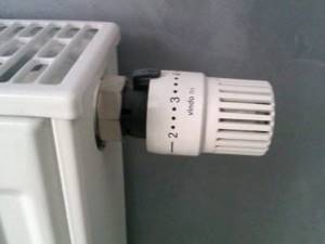
Thermal valve function
The thermal head and thermal valve are an integral element of the radiator heating mechanism. When the system is connected, the valve receives temperature readings that can be adjusted. Today, two-way and three-way valves are common. The thermal head and thermal valve are the “heart” of the heated floor.
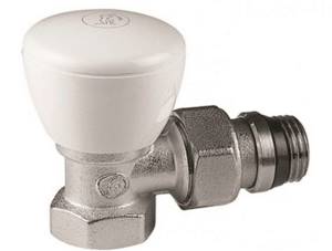
Installation
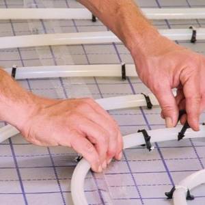
Installing a heated floor is a troublesome task and, as it may seem at first, costly. However, subsequently the benefits and benefits are obvious. As practice has shown, during operation such a system turns out to be cheaper and more practical than other types, but installation will cost more than for other systems. All costs will be recouped, and as a result, the heating season will help save up to 20%. It is better to entrust the installation of such a floor to qualified specialists, which can guarantee safety.
Rules for refueling the system
Setting up the operation of a heated floor cannot be done if the coolant flow in the loops changes spontaneously. This phenomenon is typical when there are air locks, so the heating system must not only be properly organized technically, but also properly charged.
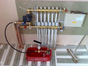
To fully fill the system, automatic air vents must be installed on both branches of the underfloor heating collector. If the loops are located at a level above the collector, the supply connection to the latter must be made through a deaerator. Refilling the underfloor heating system is carried out separately from other heating circuits, that is, the piping of the generator part and the radiator network must be filled in advance, and the shut-off valves at the collector inputs must be closed.
To fill the coolant into the system, a hose from the water supply system or pump is connected to the drainage outlet of the supply branch of the collector. Accordingly, a hose must be connected to a similar outlet of the return branch to bleed the air, the return end of which is either led outside or lowered into a container with a volume of 30–40 liters.
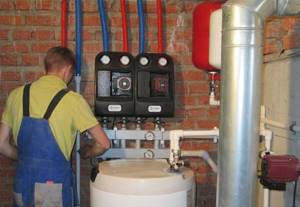
The first thing to fill in a heated floor system is the manifold and its piping. In this case, the flow meters on the supply branch must be completely open, and the regulators on the return branch must be closed. Next, you need to sequentially fill each loop with coolant until clean coolant without air bubbles comes out of the bleed hose. The heated floor is filled with a minimum flow to uniformly squeeze out air from the system. When all the underfloor heating loops are filled, you can put the heating system into operation and balance it.
Tips for choosing
It is best to purchase a ready-made kit, which already includes all the taps and other necessary components. Different amounts of space have their own installation systems, so the method of installing equipment for a small apartment will not be suitable for a large house.
When installed correctly, such a floor should not be visible under the parquet. It is worth considering that the more programming functions for a heated floor, the more expensive it will be. For example, you can choose different temperatures for different rooms.
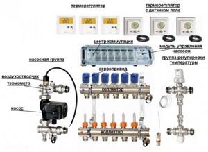
When choosing one heating scheme or another, it is always necessary to take into account the volume of the heated room.
In order to save money, the space under cabinets, sofas and other types of furniture is not insulated.
You need to carefully select the heat insulator material, on which the durability of the system largely depends - penoplex and polystyrene foam are the most common options.
Reasons for selection
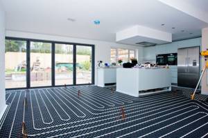
Three main conditions should be taken into account when choosing the type of control valve:
- Room area. The larger the cubic capacity of the room that requires heating, the more difficult and often it is necessary to make adjustments, so it is necessary to install automation here.
- Pipe section. The valve passage must be no less than the pipe Ø. If it is larger, then an adapter is placed on the smaller pipe.
- Maximum flow (throughput). The characteristic is set when designing a heated floor.
If floor heating is carried out in small rooms with an area of up to 10 m² and is not the main heating system in the house, then coolant can be supplied to the circuit through 2-way taps. Such a device will automatically supply the required portions of hot water to the connected loop, maintaining the desired temperature.
Installation Rules
Failure to follow the rules for installing the mechanism may result in incorrect operation or complete failure of the system. According to manufacturers, with proper installation and operation, a heated floor can last up to 50 years for its owner, so it is important to approach such a purchase thoroughly.
Reviews
Numerous reviews indicate that the water heating system is popular due to its efficiency and availability. Among the factors and selection criteria, people emphasize safety compared to electrical systems.
Among the common manufacturers are the brands WOLF, ACV, VAILLANT, CTC. Pipes and other components are offered on the market by companies such as OVENTROP, WIRSBO, UNIVERSA, AQUATHERM and PURMO.
To learn about the functional role of the thermal head in the floor heating control system, see the following video.
Source
Manual adjustment of TP collectors
The simplest, although time-consuming, setting method is to adjust the temperature of the heated floor using manual valves. The task is somewhat simplified by installing flow meters (rotameters) on the comb.
Flow meters simplify the dosage of the amount of circulating coolant (flow) in one separate circuit of the underfloor heating system. In the case of group temperature control throughout the collector, the rotameter can also be used to balance the flow of coolant (smoothing out the difference in hydraulic resistance) along loops of different lengths.
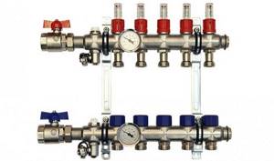
The main elements of a flow meter valve are:
- housing with shut-off and control valve. It is screwed into the corresponding technical hole of the manifold;
- a flask made of transparent plastic or glass with a printed scale;
- float indicator that allows you to visually control the flow of liquid through the rotameter.
Manual adjustment of the underfloor heating manifold is carried out by screwing/unscrewing manual valves or adjusting the throughput of flow meters.
Important! Improvement in the efficiency of the underfloor heating system, as a result of its manual adjustment, will be noticeable only in the case of intensive circulation of the coolant through it. This can only be achieved by using a separate heat pump.
The sequence of manually setting the temperature of a warm water floor
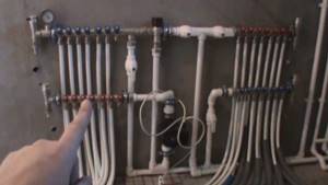
At the beginning of the adjustment operations, it is necessary to make sure that the pipelines of the TP system (secondary circuit) are completely filled with coolant and have no air pockets. They are filled following the main heating system (primary circuit). At this time, all shut-off and control valves on the collectors must be closed.
After opening the main valves for the supply and return of the distributors for heated floors, the shut-off devices on each of the loops are opened sequentially. Air is bled through Mayevsky valves or automatic comb air vents. It is recommended to fill the next branch only after the previous one has been completely filled and its air has been guaranteed.
Having completed filling the first loop, it is necessary to turn on the heat pump of the secondary heating circuit and circulate the coolant through its system. The efficiency of liquid circulation is checked with built-in or overhead thermometers. As a last resort, you can simply put your hands on the supply and return pipes at the same time - they should be warm, but with a slight difference in heating.
The filled first loop should be cut off from the collectors at both ends using local shut-off and control valves. Then, the above actions are carried out with the next loop.
After sequential filling of all heat pump circuits, their shut-off devices are opened and the heat pump is switched on to operating mode. The temperature of the warm water floor is adjusted through the supply of coolant to each of its branches. It is set by changing the liquid flow rate (with a valve or rotameter), and control is carried out by changing the temperature gradient between the supply and return flow. Ultimately, this difference for different circuits should be the same, within 5-150C. The longer the loop, the more intense the coolant will cool and the greater its consumption required.
Important! Heat exchange in underfloor water heating systems occurs with great inertia. The delay in heating the coating surface is especially noticeable if the pipes are laid in too thick a concrete pour (over 60-70 mm). Sometimes the effect of changing the coolant supply intensity becomes noticeable only after a few hours.
To monitor the correct adjustment of a warm water floor, it is rational to use non-contact laser or contact electric thermometers. Their installation to measure the temperature of the supply and return pipes will help reduce the time to obtain the result of changing settings from several hours to 10-15 minutes.
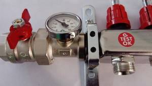
Features, functionality
The functioning of the entire water floor structure is based in the mixing unit, which plays an important role as a coolant temperature regulator. This is due to the fact that water is supplied from heating equipment with a fairly high degree of heating - up to 90°C, and on the floor surface this figure should not be higher than 40°C.
Operation of a water heated floor system
The thermal head, which is installed on the valve, is responsible for maintaining a stable coolant temperature. In the mixer, liquid flows are mixed, coming with high heat from the supply and cooled from the return or water supply, which makes it possible to direct coolant with the desired temperature into the water circuits.
Methods for adjusting the temperature of heated floors, RTL adjustment and other methods
Reverse flow regulators - RTL taps - will help make a heated floor circuit simpler and cheaper. The most famous companies producing heating equipment offer consumers their thermostatic RTL taps - flow limiters for heated floors. What are the features of such temperature control, we will consider further. Also, how the temperature of the heated floor is usually regulated and what it is needed....
What temperature should it be
The highest comfortable temperature for a heated floor is 28 degrees. Comfortable temperature for long-term use can be adjusted individually according to preferences. But usually it is lower - 22-26 degrees, so that the floor covering “becomes invisible”.
In separate rooms where people are not constantly present, it is usually good if the temperature is slightly higher - up to 32 degrees. This is an entrance hall (veranda), toilet, bathroom.
To maintain the temperature at a given level, two different methods are used.
Ways to maintain the temperature of a heated floor
The first method is based on a stable high speed of coolant movement. In order for the temperature of the heated floor to be stable, a certain amount of thermal energy must be supplied to it using a coolant. The coolant is prepared at a given temperature and passes through the circuit in a significant volume.
The volume should be such (the speed of movement should be such) that at the exit from the circuit the temperature of the liquid does not decrease by more than 10 degrees. Then within the circuit the temperature difference will be insignificant and hardly noticeable. For example, 45 degrees are supplied to the circuit, and 35 degrees will be output. And the surface temperature can be 28 degrees.
The second method is to supply liquid at high temperature, but intermittently, in portions. A portion of hot liquid fills the circuit quite quickly (within a few minutes), after which its movement stops.
The liquid cools and releases energy to the screed. The heat-intensive screed gradually absorbs and dissipates energy without overheating at the location of the pipeline. As soon as the coolant cools down to the set value, a portion of hot water is again supplied to the circuit.
For example, a liquid of 75 degrees can be supplied to the circuit, and it will be replaced after cooling to 30 degrees. Due to the distribution of heat in the massive screed, the floor surface will be maintained at about 28 degrees all the time.
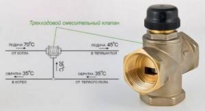
Temperature control diagram for the mixing unit
To regulate the temperature using the first method, maintaining a significant speed of liquid movement, you need to install a mixing unit in which water is prepared to a given temperature.
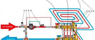
The coolant from the boiler arrives at 65 - 80 degrees. To reduce the temperature to the required 40 -50 degrees, a displacement unit is installed, which supplies part of the return from the heated floor with a temperature of 30 - 35 degrees to the input of the circuit. As a result, the thermostatic head at the inlet, which regulates the ratio of incoming flows, maintains a set temperature, for example, 45 degrees.
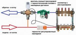
It is not difficult to assemble such a circuit yourself, which will be cheaper. The basis is a three-way valve, the stem of which is adjusted by a thermal head. It is more expedient to install the control element of the thermal head on another branch. The installation location of the pump and three-way valve (supply/return) does not matter. But the pump must be installed in the underfloor heating manifold circuit (behind the three-way supply valve), otherwise the three-way valve will not work.
By adjusting the thermal head to a certain return temperature, we can set the temperature of the heated floors in a wide range. But to obtain colder circuits, all that remains is to reduce the speed of movement of the coolant in them using control valves on the manifold.
Scheme for adjusting the temperature of heated floors using flow limiters
The second method of portioned supply of hot liquid to underfloor heating circuits is carried out using RTL thermostatic taps (flow regulators). A mixing unit is not used - high-temperature coolant, which is needed for the radiator network, is supplied to the circuit.
An RTL valve with an RTL thermal head is installed on the return of each circuit, which opens when the liquid cools to a given temperature. As soon as the temperature of the passing liquid rises above the set value (the circuit is filled with hot water), the tap almost completely stops its movement until it cools.
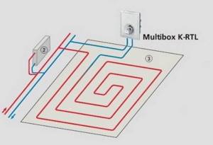
These taps are installed only on the return line in order to quickly respond to temperature changes in the circuits. In fact, RTL taps regulate the flow - quantity per unit of time (liter/minute). They work depending on the heat loss of each room (circuit, screed area limited by expansion joints), depending on how quickly the screed cools.
Features of the design of RTL cranes and RTL uniboxes
The RTL tap has a brass or copper core, which is in close contact with the same core of the installed RTL thermal head, so the temperature is very quickly transferred to its working fluid.
The RTL thermal head only responds to liquid temperature. If it exceeds the level specified by the regulation, the valve shuts off the flow.
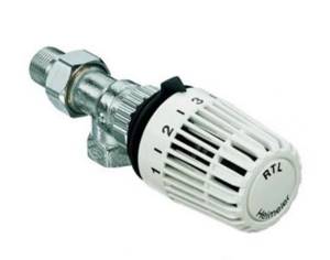
The RTL thermal head looks very similar to conventional thermal heads that are installed on radiators and which measure air temperature. Therefore, bewilderment often arises - how the head on the manifold “through the air” regulates the warm floor in the bedroom...
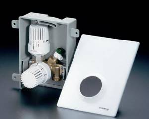
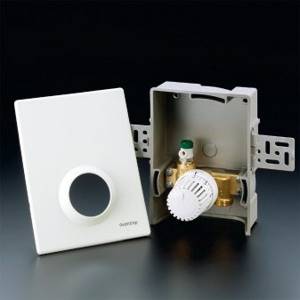
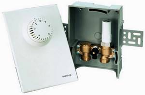
The RTL Unibox is a faucet and a thermal head combined in one housing, which can be separately mounted into the wall so that there is one cover on top with or without a thermal head. Their purpose is to regulate one circuit of a heated floor, for example, on the floor there is a heated floor only in the bathroom. The use of uniboxes is economically beneficial, since there is no need to install a mixing unit for only one circuit.
But the design can include not only an RTL head, but also an air thermal head, in order to at the same time control the air temperature in a small remote room, where a warm floor may be the only heating device.
Where is it beneficial to use RTL flow control in heating systems?
The design of the RTL manifold is very compact. There is no pump and mixing unit, and the return manifold itself can be assembled from tees, at the inlets of which RTL taps with heads are installed. Therefore, this system is advisable or indispensable where there is no space for the installation of volumetric structures. For example, this could happen in an apartment.
Also, a system with reverse flow control is very beneficial if there are few circuits or only one circuit. In this case, installing an entire mixing unit with a pump is simply not profitable. Uniboxes are used, as mentioned above.
How is RTL adjustment used and what are the limitations?
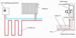
The underfloor heating circuits are connected to the main supply line simply in parallel, like a branch of radiators or one radiator. The supply to the heated floor circuit is carried out by a branch from the supply line. And on the return from the circuit, an RTL tap is installed on the manifold or a separate one (unibox), which is then connected to the common return.
The number of circuits with reverse flow control can limit the pump performance in the boiler (in the system).
The next limitation is the heat capacity of the screed. This system is designed to work with a massive concrete screed as a heating device, which can dissipate high temperature from a portion of water without overheating the surface fragments. How to make a screed with heating circuits
A general limitation to the application of backflow control is the length of the loops. The length of the circuit affects both the “filling time/cooling time” ratio and the total hydraulic resistance of a given branch from the general network. Experience shows that with circuits with a 16mm pipe, the RTL adjustment system works perfectly for circuit lengths up to 50 meters. If the circuits were made longer, then you need to install a mixing unit and use the first method.
In controversial cases, it may help to use the 20th pipe, which will have less resistance. Thus, for an RTL system for adjusting the reverse flow of a heated floor, the screed must be fragmented in advance with expansion joints, into a short contour length of 35 - 45 m.
More information – boiler protection with a mixing unit
Three-way valve
According to the design solution, the three-way valve has three holes, two of which serve for the flow of mixed water flows, and the third discharges the coolant into the water circuit system. The piping scheme provides for a branching on the return line, which allows excess cooled coolant to be sent to the water heating device.
Structure of three way thermostatic mixing valve
The three-way valve body is made of corrosion-resistant materials such as bronze. The main part of this device is the thermal head, which is installed on the rod through a special axle box.
During the operation of the heated floor, it reacts to the ambient temperature, changing the location of the axle box and adjusting the degree of heating of the outlet water in accordance with the set values.
To read the temperature, the thermal head is equipped with a sensor that transmits signals to the actuator, which, depending on the values received, closes or opens the valve. It is mounted so that the thermal head is in a horizontal position. When the pipeline length is over 40 meters, a circulation pump is installed to circulate water through the circuits.
Types of control valves
Although the purpose of all valves is the same - to distribute the heating level of the coolant in the pipes, they still differ in control methods.
There are the following types of devices:
- manual;
- with electric drive;
- with thermal head;
- pneumatic;
- with hydraulics.
For a private residential building, a three-way valve for heating with an electric drive would be preferable. Changes in the characteristics of the coolant are made thanks to special sensors that transmit commands to the electric drive through the controller.
The desired temperature distribution effect occurs automatically, regardless of what heating equipment is installed in the house - solid fuel, gas or electric boiler.
Two way valve
The wiring diagram for an easy-to-use heated floor with a three-way valve is attractive due to its versatility. But it should be borne in mind that for small heated rooms you can use a cheaper two-way valve, the design of which also includes a thermal head equipped with a sensor. This device supplies cooled coolant constantly, and hot liquid is supplied as needed.
Mixing unit for underfloor heating on a two-way valve
Diagram of a unit with a two-way valve
After mixing, the liquid at a set temperature, controlled by a sensor, is supplied to the manifold. Two check valves are additionally installed on the return circuit, preventing the flow from moving in the return direction.
Three-way valve capabilities
If the comb has a three-way valve, then the adjustment is done using a servo drive. In this case, the mixing valve will control the indicators. During this process, the three-way valve can be turned as desired and as many times as necessary. But setting the mixing valve is more difficult.
Why do you need a comb for a heated floor? Let's look at its structure and operating principle, how to choose it, instructions with photos and videos on how to install and configure it or do it yourself.
There is another opportunity to adjust heating floors - using a modular mixer, it consists of:
- three-way valve;
- thermometer;
- bypass;
- pump for liquid circulation;
- thermostatic head;
- relay.
This set costs a lot, but its effectiveness is high. There is a prerequisite for the functioning of this module - European assembly.
Another method of adjusting heated floors is to install a servo drive and a thermostat. The thermostat notifies the servo drive about the temperature drop in the room and the need to supply heated coolant. This method works even when assembling the collector yourself.
A warm water floor is a complex structure, and when you decide to build it in your home, you need to be aware that it is not enough to install the system, you must periodically adjust it according to the instructions. And it is important to understand this process, otherwise the floor will not live up to your expectations.
Return temperature limiter
Regulator for water heated floor Unibox Rtl Oventrop
Such a scheme involves installing the Unibox Rtl Oventrop so that the coolant, when circulating, passes the entire circuit of the heated floor and only then through the Rtl regulator.
The principle of its operation differs from the functioning of the mixing unit, where in order to achieve the required temperature, liquid flows with different degrees of heating are mixed, controlled by a valve.
Such piping involves supplying hot coolant in portions, so that overheating does not occur. An inertial screed also helps smooth out the temperature.
Design dimensions of Rtl valves
When equipping a water heating circuit system with an Rtl valve, it should be taken into account that the temperature set on the return liquid flow limiter should not be lower than the room air values.
If this requirement is not met, then unstable and incorrect functioning of the Rtl regulator may occur.
Structurally, it consists of a housing, a limit rod stroke limiter, as well as a liquid sensor, thanks to which data on the temperature of the passing flow is transmitted to maintain the set heating value in automatic mode.
Water heated floor control scheme
The Rtl valve opens only if the maximum value has not been reached. A similar regulator is also used when equipping a combined-type warm water circuit, when the coolant flows in parallel to the radiators and into the system.
A variety of options for connecting a water heating circuit allows you to rationally decide which circuit will be suitable for specific conditions. In country houses, when installing a local boiler with an adjustable temperature of the outlet water flow, there is the possibility of direct connection without additional components designed to reduce the degree of heating of the coolant.
Typical connection diagrams
Water heated floors are rarely used as the only source of heating. Heating only due to underfloor heating is permissible only in regions with a mild climate, or in rooms with a large area, where heat removal is not limited by furniture, interior items or the low thermal conductivity of the floor covering.
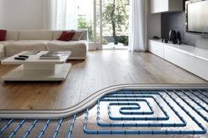
Almost always it is necessary to combine radiator circuits, hot water preparation devices and underfloor heating loops in one heating system.
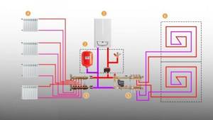
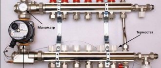
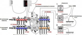
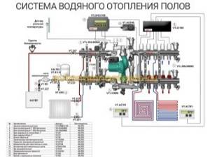
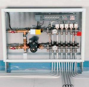
Typical diagram of a combined heating system with connection of radiators and underfloor heating circuits. This is the most technologically advanced and easily customizable option, but it also requires significant initial investment. 1 - heating boiler; 2 — safety group, circulation pump, expansion tank; 3 - manifold for separate two-pipe connection of radiators in a star configuration; 4 — heating radiators; 5 - underfloor heating manifold, includes: bypass, three-way valve, thermostatic head, circulation pump, combs for connecting underfloor heating circuits with gearboxes and flow meters; 6 - heated floor contours
There are quite a large number of variations in the design of the boiler room piping, and each individual case has its own principles of operation of the hydraulic system. However, if you do not take into account very specific options, then there are only five ways to coordinate the operation of heating devices of various types:
- Parallel connection of the underfloor heating collector to the main line of the heating unit. The insertion point into the main line must be made up to the connection point of the radiator network; the coolant supply is provided by an additional circulation pump.
- Association according to the type of primary and secondary rings. The line, wrapped in a ring, has several supply connections in the supply part; the coolant flow in the connected circuits decreases with distance from the heating source. Flow balancing is performed by selecting the pump supply and limiting the flow with regulators.
- Connection to the extreme point of a coplanar manifold. The movement of the coolant in the heated floor loops is ensured by a common pump located in the generator part, while the system is balanced according to the principle of priority flow.
- Connection through a hydraulic separator is optimal when there are a large number of heating devices, a significant difference in flow rates in the circuits and a significant length of underfloor heating loops. This option also uses a coplanar manifold, but the hydraulic arrow is necessary to eliminate the pressure drop that interferes with the correct operation of the circulation pumps.
- Local parallel loop connection via unibox. This option is well suited for connecting a short-length heated floor loop, for example, if you need to heat the floor only in the bathroom.
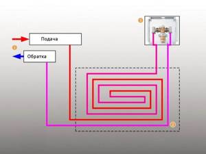
The simplest option is to connect a heated floor circuit to a radiator heating system with a coolant temperature of 70-80 °C. 1 - line with supply and return of the high-temperature circuit; 2 - heated floor contour; 3 - unibox.
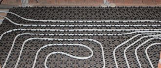
It must be remembered that the nature of the operation of a heated floor may also change depending on the installation pattern of the coil. The “snail” scheme is considered optimal, in which the tubes are laid in pairs, which means that the entire area is heated almost evenly. If the warm floor is arranged as a “snake” or “labyrinth”, then the formation of colder and warmer zones is practically guaranteed. This drawback can be eliminated, including through proper configuration.
