Today, the electric floor heating system is one of the most comfortable for humans. Heated air rises up from the very base. Therefore, its highest temperatures are observed at a distance of up to 50 cm from the floor. They will be lower under the ceiling.
The operating principle of any convector or radiator is to direct the flow of warm masses to the ceiling, while the already cooled air will concentrate below. Because of this feature, electric heated floors are cost-effective.
A thermostat is used to control its operation. They come in various types. However, the thermostat circuit has a common principle for all models. To install it yourself, you need to consider this procedure in more detail.
General information
No underfloor heating system can do without a thermostat, the connection diagram of which is identical in almost any model. If this device is not used and the heating wire is connected directly, the system will reach its operating temperature limit. This has a detrimental effect on the screed, and in the case of a wooden floor will lead to its deformation.
It should also be noted that no manufacturer of electric heated floors provides a guarantee for their product unless a heating control device is installed. Therefore, the thermostat circuit must be studied before installing floor heating.
Moreover, in this case, a regular timer or dimmer will not work. Only thermostats intended for this purpose may be used in an electrical circuit. They come with a sensor that measures temperature.
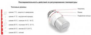
Adjusting the heated floor temperature
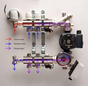
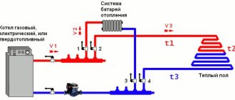
Scheme for adjusting the temperature in the system using a servo drive.
The simplest adjustment option is with manual taps. A slightly more comfortable option is automatic thermostats with sensors and servos, but only with the additional installation of a restart valve and switching unit. In addition, there are other ways to regulate the heating of floor water systems:
- change in coolant flow;
- change in coolant temperature.
The second method is used especially often and involves the installation of a three-way valve, which is entrusted with the function of controlling the mixing unit. The relay output of the temperature sensor is connected to the solenoid of the electric shut-off device: at the slightest excess of the temperature of the value set in advance, the valve opens, causing the cooled water to mix with the incoming liquid, reducing the heat capacity.
Types of thermostats
There are various types of underfloor heating systems and thermostats themselves, which manufacturers allow you to install yourself in accordance with the instructions.
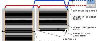
Warm floors can be cable, matte or infrared. The first two systems are single-core and double-core. Each of them has its own installation features. Infrared heated floors are similar in connection principle to a two-core cable. Therefore, the connection diagram for the thermostat for these two different types is identical (which cannot be said about the installation of the system itself).
Thermostats differ in the method of control - mechanical, digital and programmed, and in the method of measuring heating - into devices with an air, floor or combined sensor. There are also certain installation conditions for these varieties.
Thermostat functions
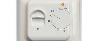
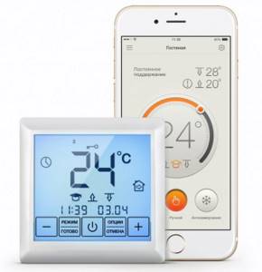
The thermostat can only operate if a temperature sensor is installed that measures the heating intensity of the floor surface or air. The thermostat itself is designed to maintain the specified heating parameters by turning the heating elements on and off in a timely manner.
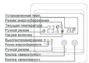
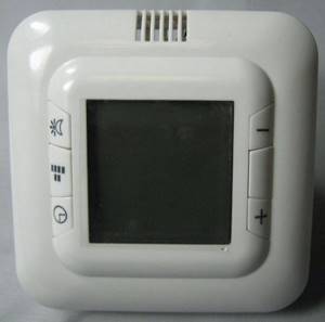
Basic functions and control panel of the thermostat
Thus, the thermostat not only prevents overheating of the floor heating system, but also contributes to significant savings in energy consumption. After all, the heating device is turned on only when the temperature drops. Despite the rather high cost of the control device, during the operation of underfloor heating it fully pays for itself in savings on electricity costs.
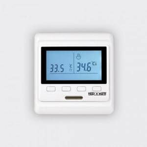
Heated floor thermostat
The most important thing is to ensure that the temperature sensor is working properly. After all, it is he who sends a signal to the thermostat about the need to turn the heating elements on or off. This means that they will not overheat, which will significantly increase the service life of electric floor heating.
What is important when choosing a device
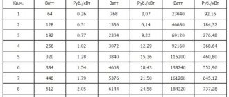
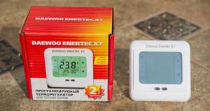
Initially, when purchasing a heating control device, you should pay attention to its load limit. Most often, devices on sale are rated at 16 A. This is approximately 3.7 kW.
But there are devices designed for less load. The power of an electric heated floor should be correlated with the maximum load of the thermostat.
The most comfortable device is considered to be one that simultaneously includes a sensor for measuring floor and air temperatures. But most often the product has only one measuring point.
The connection diagram for a heated floor thermostat with a coating sensor and a double set are identical. But if the device has a built-in indoor air heating meter, it will have two fewer terminals than previous varieties.
Which floor thermostat is better to choose?
The large number of models on the market makes purchasing the right device difficult. Plus, not all of them are of high quality and will last at least the stated warranty period. Therefore, when choosing a thermostat, you should pay attention to some parameters.
Specifications:
- By operating principle: mechanical thermostat or electronic?
- Is the temperature sensor external or built into the floor?
Phasing on the thermostat
A common question is: is there a difference where to connect the phase on the thermostat and where to connect the zero?
Yes, I have. This does not affect the operating logic of the device, but it does not affect the safety.
If you confuse the phase and zero, then when the thermostat is turned off, it will not be the phase conductor that will break, but the neutral one. Thus, the phase will be constantly present on the underfloor heating cable, which is naturally not safe.
In those devices that have a separate switch on the case, when it is pressed, two conductors are broken at once, both phase and zero. But this is in manual shutdown mode, and not in all models.
Often the zero is fed directly through its track. I went into the terminal and immediately went to the heated floor.
In this case, the switch itself is only responsible for interrupting the power supply to the control board. When automatically triggered by a sensor, only one wire is always broken.
Also note that the protective grounding is directly to the thermostat itself at src=»https://domikelectrica.ru/wp-content/uploads/2019/12/67.jpg» class=»aligncenter» width=»700″ height ="434″[/img]
This can be a separate, separate terminal through which the heating cable shield is connected to the protective conductor.
The thermostats themselves even have a “square within a square” icon, which means a device with double insulation.
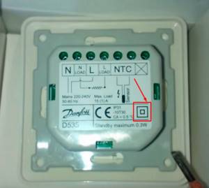
These marks are typically found on portable tools that do not require a grounding pin on the power cord plug.
Types of control
For each type of room, you should choose a specific type of heating controller. For the bathroom it is better to purchase mechanical varieties.
The connection diagram for a heated floor thermostat most often involves installing this device near an outlet indoors. The bathroom is often damp and there are significant temperature changes. Devices with digital displays will work less under such conditions.
Therefore, mechanical control is relevant here. In the kitchen, room or hallway, you can install a digital thermostat that will show the heating level on the screen.
There are programmed devices on the market. They are given a temperature based on time. He works according to this program for a week, then the cycle repeats. The thermostat connection diagram does not differ depending on the type of control.
Control options
- power is supplied to the device after pressing the “0” button (if connected to the network);
- Changing the temperature in most device models is done using the “^” and “v” buttons. At the same time, you can control the temperature change on the display;
- when the device is operating, the “Set” indicator usually lights up;
- Using the “^” and “v” buttons you can set the required temperature in the system;
- the “Run” indicator signals that the system has reached the set temperature;
- The device is turned off using the “ON/OFF” button.
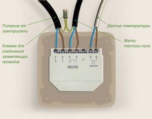
Wire connection principle
Depending on the type of thermostat, a certain type of connection will be made. It is clearly indicated in the manufacturer's instructions. The electrical circuit of the thermostat may have 4, 6 or 7 terminals.
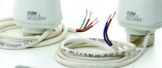
In the first case, a device with an air sensor is connected. Two terminals (the number is indicated in the instructions) are intended for underfloor heating wires. The brown conductor is connected to compartment L (phase) for the heating system, and the blue conductor is connected to N (zero). Communications from the network are also connected in accordance with polarity.
If the device has 6 terminals, then the kit includes a sensor. It is connected without regard to polarity into the connectors specified by the manufacturer.
The seventh terminal is for grounding (yellow-green wire). If there is one in the house, but the device does not have a corresponding connector, the connection should be made outside the housing. And if there is no grounding in the house, the yellow-green floor wire is grounded.
Preparing for work
Before installing the temperature controller, carefully read the instructions provided by the manufacturer. The section devoted to the installation of the device itself deserves special attention, because the procedure for performing this activity differs for different models.
Thermoreg TI-200 thermostat. Instructions
Thermoreg TI-200 thermostat
Thermostat UTH-150 Euro type. Certificate and installation instructions
UTH-150 Euro type
Remove the front panel of the regulator by carefully removing the control wheel. To do this, carefully pry the element with a screwdriver, and then unscrew the securing screw. If the regulator model you choose is equipped with latches, simply press them with a screwdriver and the panel will come off.
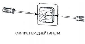
Removing the front panel
Important! If the cover cannot be removed, there is no need to try to solve the problem by applying mechanical force. This way you risk breaking the fasteners. As a result, you will have to buy a new regulator. It is better to carefully read the manufacturer's manual and disassemble the device in accordance with the given sequence.
Thermostat E 62.116.
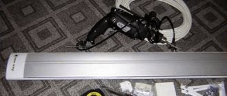
Instructions Prepare the following equipment for mounting the device:
- corrugated tube. In most situations, this product is included in the factory configuration. If specifically in your case the manufacturer did not equip its product with a corrugated mounting pipe, purchase it separately. A tube with a 16 mm diameter is optimal. To determine the required length, measure the space between the installation locations of the heating system regulator and the temperature sensor;
- screwdriver;
- mounting screws;
- installation box;
- level;
- indicator screwdriver. Designed to determine the voltage in the network. Can be replaced with another device with similar functions.
Some recommendations
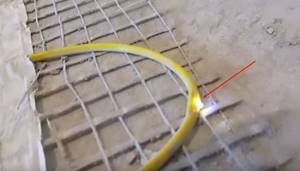
A do-it-yourself thermostat circuit involves not only the correct connection of the wires. The remote sensor (if included in the kit) is installed in the corrugated pipe. Its edge in the floor is insulated. This way the sensor can be removed if necessary.
The installation level must be at least 50 cm from the floor. If it has an air sensor, the installation height should be at least 1.5 m.
If the owners have small children, it is necessary to purchase models with special protection. This will guarantee that the child will not adjust the thermostat on his own.
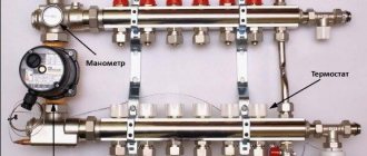
Thermal valve - the main element of a water heated floor
The device allows you to significantly simplify and optimize the operation of the heating system by adjusting the flow of hot and cold water into the pipeline.
Thus, the thermal valve is the element through which the coolant passes. The microclimate in the house essentially depends on its performance. A simple way to adjust the temperature of a heated floor
Design features of the thermal valve:
- The thermal head is a separate unit that is mounted on the valve stem. This part is responsible for adjusting the air temperature by changing the position of the valve box;
Characteristics of the thermal head from the thermal valve
- A temperature sensor is an integral element of every thermal head. An ultra-sensitive sensor collects data on the temperature in the room and transmits it to the board, where the program analyzes the received data and makes a decision about opening or closing the source of warm water.
Useful information about temperature sensor wiring
The thermal head should be installed correctly, that is, in a horizontal position. The same requirement applies to the valve. If you install it in a vertical position, the gas-filled bellows will record incorrect temperature readings in the house.
Installing the thermostatic head
- There is no point in installing a mixing unit with a collector in small rooms (kitchen, bathroom or balcony equipped for living). For small rooms, one valve is sufficient;
- Three-way valves are installed in large houses. A device of this type is capable of separating coolant with a temperature of, say, up to 40 degrees from hot water with a temperature of 60–70 degrees;
- In apartments with two or more rooms, experts advise installing several thermal heads for two reasons: firstly, the temperature regime in each room may differ from the others; secondly, one thermal head cannot make an individual calculation of water mixture for each room.
DIY installation
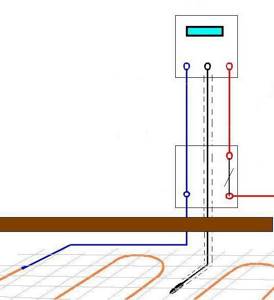
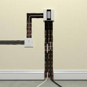
Overhead models are attached to the wall; there is no need to cut channels. The circuit of the mortise thermostat deserves attention. Typically, a space is drilled for a mounting box next to the outlet or switch.
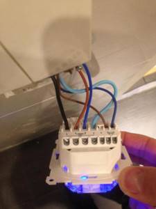
Next, a channel for the sensor and heating system wires is cut to the floor. Power is supplied from the conductors of the socket or switch (they do not have to be pulled from the panel). The thermostat is installed in a disassembled socket box.
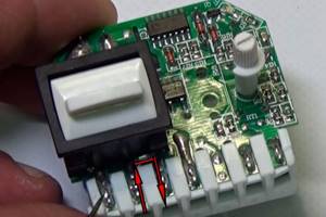
For mechanical models, you must carefully remove the adjustment wheel, unscrew the bolt and set the top panel aside.
If this is a device with a display, the top panel is removed (the technology is described in the instructions). Having connected all the wires according to the diagram with the mains power turned off, the device is inserted into the socket box. Channels are closing. The top panel is put on and the operation of the device is tested.
Having studied what the thermostat circuit for a heated floor looks like, you can quickly and efficiently make the connection yourself.
Thermostat installation method
According to the installation method, devices can be divided into:
- Invoices. They simply hang on the wall in the house.
- Built-in. To install such a thermostat, you need to do a lot of work: punch out grooves for the wires, cut out a place to mount the unit, then install everything and put it in order.
There are also those that connect to the distribution panel.
Preparatory work
Before you begin connecting the regulator, it is necessary to carry out a number of preparatory steps. First, determine where it will be located, taking into account a number of nuances:
- The device should not be installed where it may be exposed to direct sunlight; installation in drafts is not recommended. This is especially true for models with a built-in sensor, which will regulate the temperature according to the air flow of the room.
- It is also undesirable to install the regulator on external walls in contact with the street, as this may lead to incorrect readings.
- The installation height of the device is an equally important point. Installation at a height of at least 400 mm is prescribed.
- It is prohibited to install temperature control devices in rooms with high humidity, since almost no model is equipped with a moisture-proof housing. Therefore, if the heated floor is located in a bathroom, shower or bathhouse, then the regulator itself must be moved to the next room, where it will not be exposed to excess moisture.
- The temperature sensor must be located no closer than 500 mm from the wall, in the case of a cable floor model - between the turns in the center. If the film version is used, then the thermometer head is located in the center of the carbon heating strip.
For more convenient and comfortable installation, it is recommended to use an extended 60 mm socket box. This will allow you to freely position all the wires connected to the device.
For heated floors, it is recommended to install a separate dedicated power line with a copper cable with a wire cross-section of 2.5 mm, which can easily withstand a load of up to 3.5 kilowatts. Moreover, the line must be equipped with a separate 16 ampere circuit breaker.
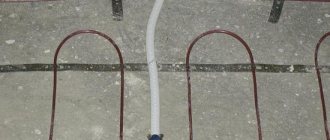
Before you start connecting, you need to make a groove from the installation site of the device to the floor. It should fit two corrugated pipes with a diameter of 10 mm. In one of them there will be wires to the “cold ends”, in the other - the temperature sensor line. It is especially useful to place the sensor in a corrugated tube, since they can often fail, and in order not to open the coating every time, it will be enough to simply pull out the old one and just as easily insert a new one.
If the screed is designed to be quite thick (35–50 mm), then the corrugated tubes do not need to be immersed in the groove on the floor. Otherwise, you will have to prepare a corresponding groove here too. The ends of the corrugation should be plugged so that the solution does not get there during the process.