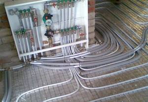
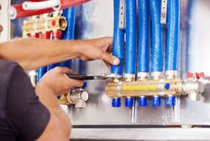
The installation of a water heated floor is impossible without installing a special device - a collector. You can build it yourself using improvised means. But it is more efficient to install a ready-made collector group, which is sold fully assembled with all components.
Heated floor collector unit
Purpose
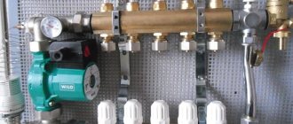
The collector unit is an important element of a water heated floor, which is designed to distribute coolant in the heating system. Thanks to the special design, hot and cold liquids are mixed inside this unit. This feature allows you to adjust the temperature of the heated floor and control its operation.
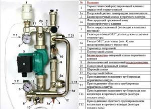
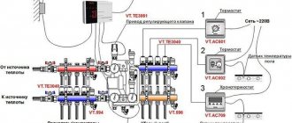
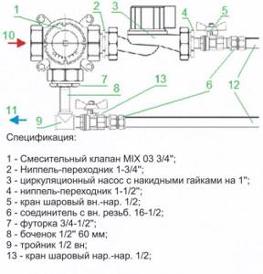
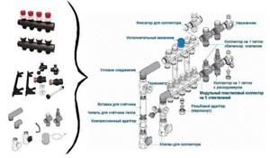
Valtec manifold assembly design for heated floors
The collector unit operates thanks to the circulation of the coolant. The heated liquid enters the heated floor, where it cools and returns back to be heated.
During operation of the device, circulating substances at different temperatures are mixed to achieve optimal characteristics. This process is controlled using several additional elements - various sensors, valves and others.
A manifold group with a pump is the most efficient. The coolant circulates through the water circuit using a forced method.
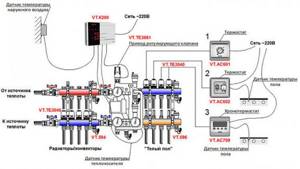
Connection diagram of the collector unit to the heated floor
This allows you to obtain productive floor-type heating, which is installed in rooms with a large area. To install a heated floor with natural circulation, it is necessary to ensure that there is an optimal slope, which can be quite difficult.
Structural elements
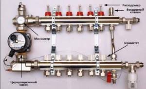
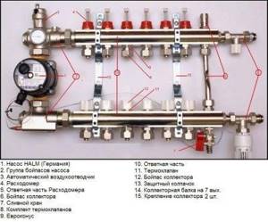
The collector unit for installing a heated floor consists of a large number of elements that ensure its efficient operation. Their list includes:
- circulation pump. Installed on the supply pipeline. The complete set of the system with a pump provides it with the necessary pressure. This makes it possible to circulate the coolant in the required volume, which increases the efficiency of underfloor heating several times;
The principle of operation of the circulation pump in the collector unit - mixing unit. This is a control valve through which the system is fed with hot water. This unit operates automatically thanks to temperature sensors. They register changes in the parameters of the coolant, after which they give a command to open the valve. It remains in this form until the temperature of the liquid rises to the desired value. A servo drive is used as a thermostat;
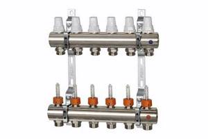
Structure of a mixing unit for heated floors - distribution comb. It is a unit that is equipped with multiple outlets for connecting the water circuit. Flow meters are installed on the comb. They allow you to distribute the coolant over different zones of the water circuit;
Comb with flow meters - air vent. Allows you to remove excess air from the system, which may interfere with its normal operation. Present in expensive models, which are a ready-made collector unit;
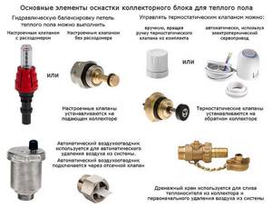
Basic elements of a heated floor collector - weather sensor Allows you to adjust the temperature of the heated floor automatically depending on weather conditions.
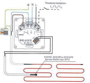
Connection diagram of a weather sensor to a heated floor system
Purpose
A warm water floor is a system that includes several heating circuits for each room. To control heating separately in different zones of the same room, two or more circuits are installed.
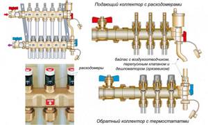
Heating comb (collector) - the device ensures the flow of coolant into the circuits of the floor heating system. The distribution unit consists of two combs - one of them is responsible for distributing the coolant from the boiler, the second collects the cooled coolant and supplies it to the return pipe for return to the boiler.
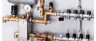
Heated floor manifold with mixing unit
To ensure that all circuits receive water at the same temperature, it is supplied to a heated floor comb - a device with one input and a number of outputs. Such a comb collects cooled water from the circuits, from where it enters the boiler inlet (and partially goes to the mixing unit). This device - supply and return combs - is also called a manifold for heated floors. It can come with a mixing unit, or maybe just combs without any additional “load”.
Materials
The manifold for heated floors is made of three materials:
- Of stainless steel. The most durable and expensive.
- Brass. Average price category. When using high-quality alloy, they last a very long time.
- Polypropylene. The cheapest. For working with low temperatures (as in this case), polypropylene is a good budget solution.
Manifold for underfloor heating with 6 circuits
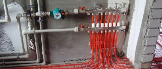
During installation, the inputs of the heated floor circuits are connected to the supply comb of the manifold, and the loop outputs are connected to the return comb. They are connected in pairs to make adjustments easier.
Equipment
When installing a water heated floor, it is recommended to make all contours the same length. This is necessary so that the heat transfer from each loop is the same. It’s just a shame that this ideal option doesn’t come around very often. Much more often there are differences in length, and significant ones.
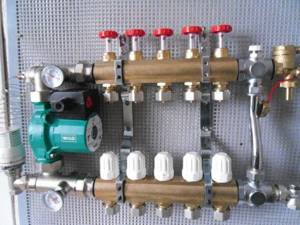
To equalize the heat transfer of all circuits, flow meters are installed on the supply comb, and control valves are installed on the return comb. Flow meters are devices with a transparent plastic cover with printed graduations. There is a float in the plastic case, which marks the speed at which the coolant moves in a given loop.
It is clear that the less coolant passes through, the cooler the room will be. To adjust the temperature regime, the flow rate on each circuit is changed. With this configuration of the manifold for heated floors, this is done manually using control valves installed on the return comb.
The flow rate is changed by turning the knob of the corresponding regulator (they are white in the photo above). To make it easier to navigate, when installing the collector unit, it is advisable to sign all the circuits.
Flow meters (right) and servos/servos (left)
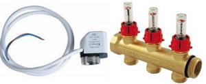
This option is not bad, but you have to regulate the flow rate, and therefore the temperature, manually. This is not always convenient. To automate the adjustment, servo drives are installed at the inputs. They work in tandem with room thermostats. Depending on the situation, a command is sent to the servo drive to close or open the flow. In this way, maintaining the set temperature is automated.
Device with 2-way supply valves
The two-valve manifold assembly has the following features:
Two-valve manifold assembly kit
- cold and hot coolant are constantly mixed. This prevents overheating of the device and extends its service life;
- the temperature change occurs smoothly, since 2-way valves have a small throughput;
- are not used in small rooms whose area is less than 200 square meters. m.
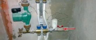
Manifold for heated floors. Mixing unit for heated floors assembled.
A manifold for a warm floor, a mixing unit , a pipe for a warm floor are the main elements of the heating part of warm water polos.
The underfloor heating manifold distributes the coolant circulating in the system along separate underfloor heating circuits, and the mixing units ensure the admixture of cold and hot coolant at a temperature specified by the user. Each circuit heats a specific area of the floor.
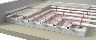
The pipe for a warm floor is a heating element of the structure. The coolant circulating through it transfers thermal energy to the concrete screed, which releases heat into the room. The best option for installing heated floors are metal-plastic or all-plastic pipes made of cross-linked polyethylene PEX-A. The main advantage that determines the widespread use of these types of pipes for underfloor heating is their high flexibility. Pipes made of cross-linked polyethylene and metal-plastic, due to their smooth, deposit-free inner surface and the absence of sharp turns, provide the least hydraulic resistance. Thermal expansion of pipes is minimal. Pipes are produced in coils of 50-200 meters or more (up to 1000 on request), outer diameters are 16, 20, 26 and 32 mm. For warm floors, as a rule, 16 mm is used. The flow of oxygen, which negatively affects the condition of the metal elements of the system, into the coolant is prevented by the aluminum layer in the metal-plastic pipe and the oxygen barrier in the polyethylene PEX-A. Metal-plastic pipes can be bent to slightly smaller diameters; when bent, they hold their shape (unlike PEX-A). Therefore, working with metal plastic is a little easier. On the other hand, a pipe made of cross-linked polyethylene, due to its greater rigidity, cannot be accidentally pressed under heavy weight or due to an impact. Both piping systems are similar in both technical characteristics and cost. An anchor bracket for heated floors is used to attach the pipes to the insulation made of extruded polystyrene foam. The thermostatic mixing valve mixes the return (cooled) and supply (too hot) coolant flows in the proportion necessary to ensure heating of the heated floor to the set temperature. For precise adjustment, a thermal head for heated floors is installed on the valve of the mixing device. Using control mechanisms, you can set both the overall temperature for the entire system and regulate the degree of heating of each circuit separately. The manifold, which is based on two distribution combs, can be equipped with a mixing unit, thermal heads, a servo drive, and a circulation pump.
Device with 3-way mixing valves
The three-valve manifold assembly is a design with the following characteristics:
- mixing of liquids with different temperatures occurs inside the valve;
Structure of a three-valve manifold - simultaneous supply of heated coolant from the boiler and liquid from the floor heating through the bypass is carried out;
- To regulate operation, a damper is placed inside the valve. It is installed perpendicular to the supply and return pipes. By changing its position, you can adjust the temperature of the coolant supplied to the floor heating;
- The disadvantage of this type of design is considered to be the presence of temperature surges. The advantage of 3-way valves is their versatility, as they are suitable for all types of water circuits.
Advantages of using collectors as part of underfloor heating
Devices that are installed assembled with all additional elements provide the following advantages:
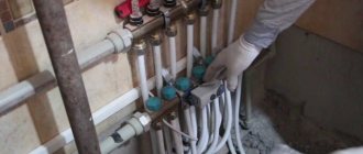
How to assemble a manifold for a heated floor
- energy savings compared to traditional heating systems (on average 30-50%);
- high safety due to the absence of open elements that could become a source of fire hazard;
- The duration of operation of the collector group is several decades. Only pipelines are subject to periodic replacement;
- Optimal microclimate parameters in the heated room are ensured.
Device installation
The manifold for a warm water floor is mounted according to the following scheme:
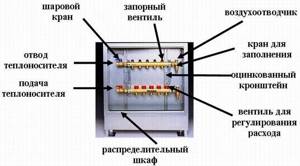
- It is necessary to install a frame under the device. It is mounted directly on the wall in a horizontal position or in a specially prepared niche. When choosing a location for installation, you should be guided by the availability of free access to the device to connect the required number of pipelines. Also, a special cabinet is often used to mount the device. In this form, the device can fit into any room.
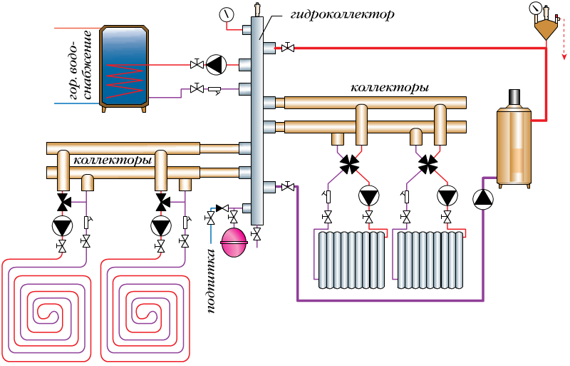
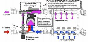
Diagram of a collector unit in a heated floor system - Connection to the heating boiler. The coolant is supplied to the system from below, and the return is placed at the top. You also need to install cut-off balls in front of the frame. A circulation pump is installed behind the taps.
- The bypass valve is being installed. It must be equipped with a temperature limiter. Behind this unit the distribution comb is installed.
- Pipelines are being laid to the heated floor. The elements through which coolant will flow into the system are placed on top. Pipelines from underfloor heating are installed from below.
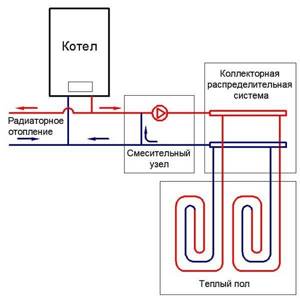
Connection diagram of the heated floor collector to the boiler - If you intend to install the device yourself, you must connect shut-off valves that are equipped with a thermostat to the distribution comb. When installing a ready-made kit, this is not necessary.
- The collector is connected to the heating system using compression fittings. This element consists of a clamping ring, a support sleeve and an intermediate nut.
- Pressure testing of the collector. After installing all structural elements, it is necessary to check how tight the resulting system is. To do this, the unit is connected to a circulation pump. With its help, pressure is built up in the system. The water circuit is left in this form for a day. After this time, the pressure is checked. If it has not changed, then the installation was successful.
Purpose and types
A warm water floor is distinguished by a large number of pipe circuits and a low temperature of the coolant circulating in them. Basically, heating the coolant to 35-40°C is required. The only boilers that can operate in this mode are condensing gas boilers. But they are rarely installed. All other types of boilers produce hotter water at the outlet. However, it cannot be run into the circuit at this temperature - a too hot floor is uncomfortable. To reduce the temperature, mixing units are needed. In them, in certain proportions, hot water from the supply and cooled water from the return pipeline are mixed. After which, through the manifold for the heated floor, it is supplied to the circuits.
Manifold for underfloor heating with mixing unit and circulation pump
To ensure that all circuits receive water at the same temperature, it is supplied to a heated floor comb - a device with one input and a number of outputs. Such a comb collects cooled water from the circuits, from where it enters the boiler inlet (and partially goes to the mixing unit). This device - supply and return combs - is also called a manifold for heated floors. It can come with a mixing unit, or maybe just combs without any additional “load”.
Materials
The manifold for heated floors is made of three materials:
- Of stainless steel. The most durable and expensive.
- Brass. Average price category. When using high-quality alloy, they last a very long time.
- Polypropylene. The cheapest. For working with low temperatures (as in this case), polypropylene is a good budget solution. Manifold for underfloor heating with 6 circuits
During installation, the inputs of the heated floor circuits are connected to the supply comb of the manifold, and the loop outputs are connected to the return comb. They are connected in pairs to make adjustments easier.
Equipment
When installing a water heated floor, it is recommended to make all contours the same length. This is necessary so that the heat transfer from each loop is the same. It’s just a shame that this ideal option doesn’t come around very often. Much more often there are differences in length, and significant ones.
To equalize the heat transfer of all circuits, flow meters are installed on the supply comb, and control valves are installed on the return comb. Flow meters are devices with a transparent plastic cover with printed graduations. There is a float in the plastic case, which marks the speed at which the coolant moves in a given loop.
It is clear that the less coolant passes through, the cooler the room will be. To adjust the temperature regime, the flow rate on each circuit is changed. With this configuration of the manifold for heated floors, this is done manually using control valves installed on the return comb.
The flow rate is changed by turning the knob of the corresponding regulator (they are white in the photo above). To make it easier to navigate, when installing the collector unit, it is advisable to sign all the circuits.
Flow meters (right) and servos/servos (left)
This option is not bad, but you have to regulate the flow rate, and therefore the temperature, manually. This is not always convenient. To automate the adjustment, servo drives are installed at the inputs. They work in tandem with room thermostats. Depending on the situation, a command is sent to the servo drive to close or open the flow. In this way, maintaining the set temperature is automated.
Tips from the professionals
When installing this device, you should pay attention to the following recommendations:
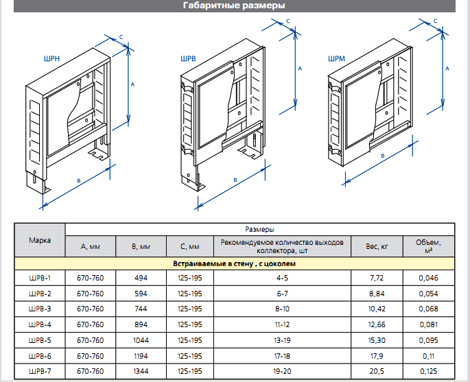
Dimensions of a wall-mounted cabinet for a manifold unit
- the thickness of the collector box must correspond to the dimensions of the unit;
- You must remember to leave free space for bending pipes from each installed circuit. It must be provided directly under the block;
- The device box is placed at a point that is at the same distance from all contours.
If you use a ready-made collector group, you can significantly simplify the installation of this device. It is very easy to install it yourself without the help of specialists. [ads-pc-2][ads-mob-2]
Installation of a manifold unit for heated floors
The collector unit for a warm water floor should be installed depending on the location of the pipelines coming from the boiler and the type of installation of the circuits. Most often, the collector unit is mounted in a wall niche in a place that is located at the same distance from all points of the system. This arrangement is required in order to maintain optimal hydraulic operating conditions. When there are very large spaces for heating with water heated floors, it is advisable to equip several flow distribution points.