A warm water floor is a low-temperature floor heating system. It can be used both as an additional heating source and as the main heating. In order to successfully apply all its advantages in practice, it is important to be able to correctly regulate the heat transfer of a heated floor to the finishing coating and control the heating operation during use. You can read about how it works and learn the principle of its operation here.
Ways to regulate the temperature of a warm water floor
Having allocated a considerable amount of funds to create a water heated floor (WF) system, the user sometimes does not receive the expected level of comfort or savings, which supporters of such heating vying with each other about.
And if the calculation of communications was carried out correctly, and the installation was carried out without errors, then, most likely, the reason for the ineffectiveness of the thermal installation is in its incorrect functional settings. These primarily include adjusting the temperature of the warm water floor. At the same time, it is based on the concepts of the temperature of the coolant in the system and the surface of the floor covering, as well as the temperature regime in the rooms. Let's look at how these concepts are linked together in practice, with different methods of TP management.
Operating principle of the temperature controller
The main function of the regulator is to control the water heated floor. Depending on the complexity of the device, both full and partial automation of the room heating process is possible.
Based on their operating principle, all thermostats can be divided into two main categories:
- The simplest manual regulators are essentially a regular faucet. The shut-off valve regulates the pressure in the heating system. Manual mode has many disadvantages, but is often used mainly for small spaces.
- Thermostatic regulator - the principle of operation is in many ways similar to that of manual control, only the signal to supply coolant is carried out by a special sensor. When a certain temperature is reached, a signal is sent to turn on the circulation pump. All actions take place according to a preset program. Programmable thermostat controllers are capable of simultaneously controlling several circuits at once and changing the heating temperature depending on the time of day and weather conditions. An automatic pressure control controller allows you to set the most comfortable mode for a person.
Don't Miss: Stem, Three- and Four-Way Faucets
There is another economical adjustment option. A temperature relay is placed on the return manifold. The device is powered in such a way that turning the circulation pump on and off is controlled via a thermal relay. The required heating temperature is set. The design of a homemade regulator is quite simple, but it is not suitable for simultaneous heating of several zones.
Design and principle of operation
In the process of laying out the pipes of the heating circuits, their ends from all rooms converge in one place, where the heated floor comb is connected to them. It is a distribution and mixing unit whose task is:
- reduce the temperature of the coolant supplied from the boiler. To supply the floor system, you need water with a temperature of no more than 45 ° C, and the heat generator rarely heats the coolant to such a low threshold. Typically, the temperature at the comb inlet is at least 55 °C;
- provide the required amount of heat for each room. Here the distribution comb works as a regulator for the release of thermal energy, controlling the coolant flow in each circuit.
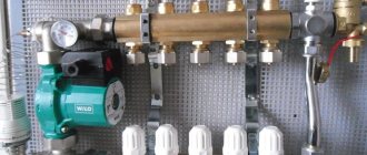
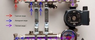
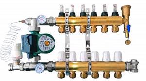
The distributor for underfloor heating visually resembles large heating combs installed in heating points. It also has 2 horizontal collectors - supply and return, to which consumers are connected, in our case - heating circuits. From the ends, coolant is supplied to the collector pipes from the main line - from the boiler room. A typical comb connection diagram is shown in the figure:
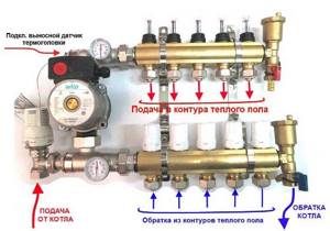
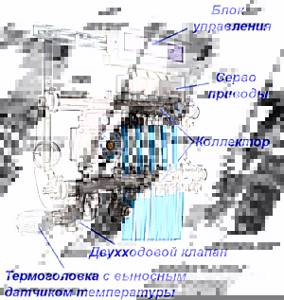
To regulate the amount of water flowing into each circuit, valves with a pressure rod are installed on one of the manifolds. Adjustment can be done either manually or using various automation tools, for example, servo drives. To control the amount of coolant, the outlets from the second collector are equipped with flow meter flasks. The comb structure is shown in detail in the diagram:
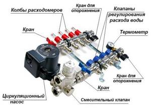
Here you can see that in addition to the elements listed above, an important part of the comb is the circulation pump. Without it, not a single circuit will be able to operate, since it is the pump installed between the two collectors that is responsible for circulating the coolant through the pipes.
Water in heated floors does not move naturally, only with forced impulse. Accordingly, in the absence of electricity, the system will not be able to function.
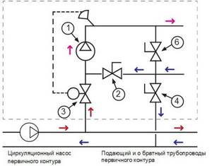
The very principle of operation of the comb is as follows. The hot water coming from the boiler enters all circuits in the required quantity, stimulated to move by the pump. Moreover, the coolant moves in a circle until its temperature drops below the set one. Since the water temperature is controlled by a three-way valve sensor, after it decreases, the valve will begin to open the way for water from the boiler line, mixing it with the cooled coolant.
When the temperature in the manifold rises to a predetermined limit, the three-way valve will shut off the line again. The comb pump for a warm water floor works non-stop, providing circulation within the system, independent of other heating networks in the house. To empty the unit, the comb design provides for the installation of drain valves. In order to release air from this separate system, the circuit can be supplemented with automatic air vents.
Temperature
Before you begin adjusting the heated floor, it is extremely important to establish a clear understanding of the purpose for which it is being done. According to the principle of operation, water-heated floors are fundamentally different from other heating devices.
The main difference is the operating temperature of the coolant. If the radiator network is supplied at temperatures up to 80 °C, then the heating of the coolant entering the heated floor coil is limited to 40–42 °C. This need is due to reasons of comfort and safety. In normal mode, the temperature on the floor surface fluctuates in the range of 22–26 °C; stronger heating causes unpleasant sensations.

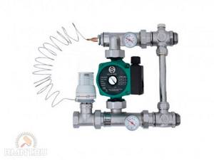
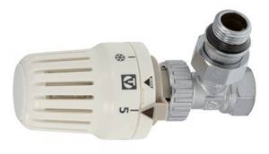
There are two ways to regulate the heating temperature of a liquid heated floor. The first of them involves controlling the temperature on the supply branch of the collector by mixing in a portion of cooled coolant from the return. Technically, this solution is implemented by installing a three-way valve with a pressure-action RTL thermostatic head. The difference between such a head and a radiator head is that it relies on the temperature of the coolant, not the air. With this control method, the flow rate in the loops remains constant, only the coolant temperature changes with a small amplitude.
The second adjustment method involves limiting the flow of hot coolant in the circuit. In this case, a thermostatic head is also installed, but it is located on a two-way valve, which interrupts the return flow circuit. With this method of regulation, the supply and return are connected by a bypass circuit, the flow through which is regulated by a restriction valve with a pre-calibrated throughput. The principle of such regulation is based on the high inertia of the heated floor system. During operation, the coolant is supplied to the loops at the nominal temperature of the heating unit; only the total flow rate changes periodically. Thus, heating of the screed occurs cyclically, that is, a significant heat capacity of the accumulating layer is required to smooth out temperature changes.
In both cases, one important rule applies: the thermostatic fittings are necessarily based on the temperature of the return flow of the loop or collector. The device can have a mechanical or electronic principle of operation, it can even be a regular thermometer
The need for correct location is due to the fact that it is almost impossible to judge the effectiveness of the adjustment based on the temperature of the coolant at the supply, because the length of the loops can differ significantly.
Heating circuit control
With high-quality temperature control of the coolant, its flow rate remains unchanged unless additional automation equipment is installed. Without them, the volume of water passing through the circuit is adjusted only manually - by valves and rotameters located on the supply/return manifold. But thermal valves can also be controlled automatically if you install servos on them.
Servo drives are attached to thermostatic valves on the return manifold and control them at the command of the controller
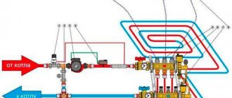
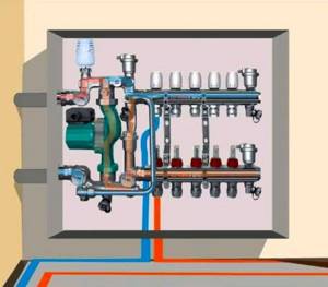
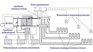
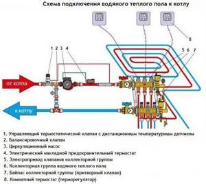
The system works like this: in the rooms there are wired or wireless thermostats that monitor the air temperature and are connected to a single control unit (controller). Receiving signals from room thermostats, it opens and closes the valves on the heated floor comb using servo drives. In this way, the controller can control underfloor heating and the radiator system simultaneously, as shown in the diagram:
In addition to temperature regulation together with thermostats, the controller can do a number of interesting things:
- respond to changes in weather conditions outside;
- preheat the required premises by a given time;
- turn off underfloor heating in unused rooms;
- controlled remotely via GSM connection or the Internet.
The use of servo drives and automation equipment not only increases the comfort for residents, but also allows you to save 15-20% of the money spent on energy costs and thus reduce the cost of heating a private home.
Operating principle and functionality
The main function of the flow meter is to ensure adjustment of the coolant along the circuits. The presence of rotameters allows:
- Control the heating of the liquid, which makes it possible to save energy;
- Ensure uniform heating of all branches of the floor;
- Avoid temperature fluctuations in different rooms;
- Conduct visual control of the volume of coolant flowing from the boiler into the main line.
For your information! The need to equip the collector group with flow meters when constructing heated floors is especially acute in a house where the rooms have different areas.
The larger the room, the lower the degree of heating. Thus, it is very difficult to achieve uniform heating without this device.
The operating principle of flow meters in underfloor heating manifolds is quite simple. The coolant, moving in the circuit, sets the float in motion, as a result of which it begins to move. Taking into account its location, the amount of water in the coil is determined on a scale printed on the flask.
Water heated floor temperature adjustment
The mixing unit always operates in the same mode with a given comfortable coolant temperature (for example, 36 ° C). In rooms where it is important for us to regulate the temperature separately, we install thermostats. We connect it all with the control unit or directly with the servos (in the case of a wired system). According to commands from thermostats, the heated floor branch is closed or opened and thus regulation occurs.
It is important to place thermostats out of the sun and away from a heat source.
There is another way to reduce the temperature in a separate room; to do this, you should slightly reduce the coolant flow along the circuit by suffocating the branch using the supply valve. However, this method does not allow it to be done smoothly and accurately. If you don’t have flow meters, then make marks and remember how many degrees you turned the valve. Otherwise, you will have to balance everything again, and this is not always easy.
Depending on what equipment is used in the heating system, it is possible to control the temperature of the assembled heated floor in several ways. In this article we will tell you about four:
- manual adjustment;
- group regulation;
- customization;
- integrated control mode.
How to adjust the temperature correctly?
Correct setting of a warm water floor is carried out according to the following indicators:
| Room | Optimal t,°C | Permissible t,°C |
| Living room | 20-28 | 18-24 |
| Kitchen | 19-21 | 18-26 |
| Corridor | 18-20 | 16-22 |
| Bathroom | 24-26 | 18-26 |
| Bathroom | 19-21 | 18-26 |
During the control process, you need to set up a device that controls water flow; it increases and decreases its supply at the right time.
Manual
With this adjustment, the entire process is done manually, and conclusions about the temperature are based on personal feelings. Naturally, with such measurements, inaccurate data is quite acceptable. Therefore, the technology for adjusting the water floor should be carried out according to this list:
- In the operation of heated water floors with laminate or parquet covering, thermal heads are used, which are mounted on both pipelines - supply and return. In manual mode, adjustments are made: the feed is increased or decreased.
- The floor temperature is adjusted only when each loop is filled with water; when filling, you need to ensure that there is no air.
- In the process of filling the pipelines with water, first of all, there must be water in the rest of the heating system. This is done by opening the taps that give access to the heat carrier to the entire system, as well as the return manifold valve. Only after this can you open the forward and return pipes of one loop and fill it completely, checking and preventing air from entering (release it into the air vent).
- The next step is to start the pump to move the water through the pipeline. Determine the heating with your hand, and when the pipes are warm to the touch, close the loop.
- The same is done with each loop.
- When all loops are filled, turn the valves to open. The water supply of each loop can be set by determining the temperature by hand.
- The temperature of the water in the pipes depends on their length, so it is advisable to install them of the same size.
Group
The group regulation process is convenient due to its accuracy of readings. It is based on an automatic increase or decrease in temperature, as well as an increase or decrease in the supply of coolant (water). This simple type of regulation uses constant circuits and climate control.
Valve with thermal head
In work performed according to the constant circuit, valves with thermal heads are used.
If it is necessary to change the temperature, the system expands or contracts the capillary tube that regulates the valve opening. This continues until the desired mode is set.
The adjustment occurs automatically. Depending on how many degrees Celsius the air in the room is, the system’s automation determines the temperature that needs to be obtained and commands the valve to close or open.
Comprehensive and individual control mode
Adjustment of floor temperature in individual mode occurs using sensors located in each room. Individual adjustment differs from group adjustment. In the first case, the climate is set separately for each room at will, and in the second, a general temperature regime operates for the entire system.
Connection diagram
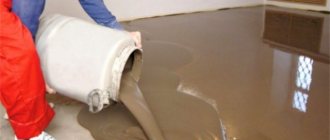
Assembling a heated floor is not a difficult job, according to experts. First, the heating parts are laid, which are then filled with screed (cement + sand + water). And the coating is laid after the mixture has hardened.
After all this installation work, you can start connecting a water floor heater with temperature control to a source of electricity. This is the most serious part of the entire scope of work, so you need to treat it carefully. In this section we will analyze the connection diagram to the thermostat.
Unlike installing parts and pouring screed, in city apartments connecting the structure with the energy carrier is more complicated. The reason is that such a connection is only allowed on the return pipe, because the water in the pipe coming from the boiler is very hot. In this case, it is practically impossible to control the temperature, because heating depends on the temperature values of the supply from the boiler room.
Connection diagram
But in a private house, an independent heating system functions somewhat differently. The scheme, called a collector (it distributes water in your home), looks like this: from the boiler through a common pipe, water is sent through separate tubes to the rooms, and then back to the boiler into the return collector.
Control of the water supply to each individual room is coordinated by an individual valve. And, reacting to the readings of the degree sensor, this lever automatically closes or opens. There is another control option - manual, its orientation is based on personal preferences. However, it can only be used if a water-heated floor is the only means of heating and the boiler is not hotter than 50 °C. It is imperative to install a water floor regulator if there are other means of heat delivery.
Valves that distribute water as a heat carrier are activated by commands from a thermostat (it is better to install it in the boiler room). There are two types of thermostats - those that control air heating and floor temperature. The sensors are usually located inside the housing.
Attention
The thermostat must be installed at a distance of one to one and a half meters from the floor for accurate readings. You also need to make sure that it is not exposed to direct sunlight or drafts, and that there are no sources of heat or cold nearby.
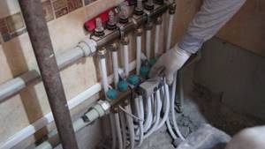
The return comb of the manifold must be connected to the servo drive. Next, run the wires from the manifold to the thermostat. The distributor box is connected by a cable to the switchboard.
The role of the servo drive in this system is to pass and close the coolant , helping the equipment not to run idle.
It is recommended, due to the complexity of the water heating system, not to install it yourself, but rather to contact a professional.
Why a comb is necessary
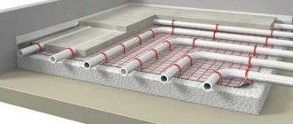
The story about the distribution comb should begin with the role of this unit in a warm floor and with an explanation of why it would be impossible to ensure normal operation of the system without it. You can see a simplified diagram of such heating in the image below. The coolant, which is ordinary water, comes from the boiler (or a centralized heating main, if we are talking about a city apartment) to the collector unit, where it is mixed with the liquid that circulated in the system previously. Then the water flows along the contours laid under the floors and gives off its heat to them.
Simplified diagram of a heated floor system
As a rule, the real scheme of a heated floor is more complex than the one in the image above - there are several contours, and they have different lengths of pipes. Accordingly, they need different amounts of coolant. But if hot water comes from a source in the form of a boiler or main without any distribution, then most of it (water) will rush into the smallest circuit. As a result, there will be overheating. Conversely, on large circuits there will be a lack of heat.
Installation and configuration of a heated floor collector - how to do it
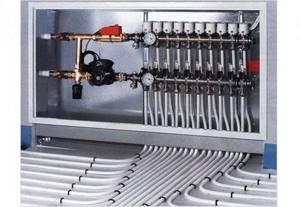
Installation and adjustment of the heated floor collector is carried out after the place for the equipment has been prepared - the base has been made, a niche for the cabinet has been made, the walls have been finished, because the device should not be contaminated with dust or solution. Where to choose a place for the collector?
Where to place the collector
It is recommended to place the collector above the level of all connected circuits. Automatic air vents should be located on the combs, and be at the highest point of the entire floor heating system. If you don’t want the floors to not work and become airy, you need to maintain the level.
It is advisable to determine the placement location in the center of the heated area in order to obtain the same length of connected pipelines. It is recommended that the difference in the lengths of the circuits does not exceed 10 meters - then balancing on the combs is possible without overloading the pump.
As a rule, manufacturers offer ready-made assembled products with the number of connected circuits from 2 to 10. All that remains is to select the one needed for the project, taking into account that at least one connection remains backup. It often happens that then it becomes necessary to add a loop - another...
Settings
The distance from the finished floor to the connection point of the pipes on the combs should be such that no obstacles are created for the convenient connection of pipelines coming out of the screed.
More often, collectors are assembled by the manufacturer to be connected “on the left”. If it is necessary to connect “on the right”, the product components are rearranged in accordance with the instructions.
Usually, shut-off valves and trim valves are rearranged, the mixing unit and bypass are deployed.
It may also be necessary to rotate the pump 90 degrees in order to reduce the overall size of the product. This is usually not difficult to follow the instructions.
Consolidation
The easiest way to fix the collector is to use a special cabinet, built-in or wall-mounted.
The cabinet not only serves as a piece of furniture, but also protects equipment and pipelines from accidental impacts. The collector is secured using the screws provided in the kit.
The collector should not be attached directly to the supporting structures of the house. This can cause vibration and sound to be transmitted throughout the home, increasing noise levels from equipment. Use standard mounting schemes provided by the manufacturer. Use a special cabinet or racks, shields with vibration dampers.
Equipment, collector design
Let's look at the installation of a collector using the example of a product from one of the manufacturers. This collector is assembled according to a common scheme and includes standard components.
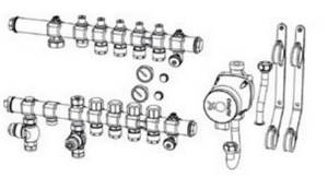
Let's take a closer look at what the heated floor collector-mixing unit consists of, using an example.
- 1. Circulation pump.
- 2. Balancing valve. It is necessary to compensate for the lack of water flow in the supply line. In order to ensure the nominal coolant flow in the circuits...
- 3. Thermostatic valve with thermal head. Controls the temperature - regulates the amount of coolant to achieve the set temperature.
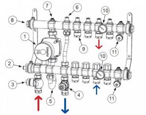
- 4. Balancing valve. Serves for initial setting of the heated floor system by temperature for operation in a given network. It also performs a protective function against excessive temperature rise in a heated floor by setting an initial limit on coolant flow.
- 5. Bent tube for connecting the pump.
- 6. A bypass with a control valve is necessary to prevent overheating of the pump if all manifolds are closed.
- 7. Manual air vent.
- 8. Glass for the thermal head temperature sensor.
- 9. Fittings for connecting heating pipe loops.
- 10. Thermometer.
- 11. Tap for draining, as well as for initially filling the heated floor system.
After fixing the collector, underfloor heating loops and supply pipelines are connected to it, while all valves and taps must be closed.
Coolant in the system
An important issue is preventing oxygen from entering the system. It is necessary to use materials, parts, and units with minimal permeability to oxygen.
Many experts agree that today only flexible pipelines containing a layer of aluminum foil are sufficiently reliable in terms of oxygen penetration.
PERT and PEX piping with an EVOH layer without an aluminum layer do not provide sufficient oxygen protection. Read more about modern piping for heated floors
If there is a possibility of the system freezing, then it is necessary to use non-freezing coolants based on propylene glycol with a concentration of up to 30%.
How to fill a heated floor system
The underfloor heating system is filled with coolant through the drain valves on the manifold. The connected loops are filled one by one.
Features of adjustment
For each individual room, the rotameters are adjusted separately. Control is carried out according to the diagram of the installed circuits
In this case, the level of heating of the liquid and pressure is taken into account
It is recommended to carry out balancing according to the following instructions:
- The total amount of coolant passing through the collector in one minute is determined. Indicators are taken in liters. The resulting value is taken as 100 percent.
- The percentage flow rate of each individual water circuit is calculated. The result is converted to liters per minute.
- The flow meter regulates the amount of liquid supplied to the pipeline.
Using these steps, you can perform long-term adjustments to the water circuit. To indicate the actual parameters, it is necessary to observe the flow meter readings. According to observations, it is possible to accurately determine the flow rate of the circuits connected to the collector.
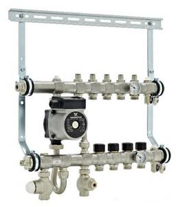
Manifold with flow meters for heated floors
The flow meter is adjusted depending on the installed model. After connecting the device to the manifold, preliminary settings should be made by setting the initial position, which allows access to liquid.
In rotameters without a built-in valve, an additional locking device is used to set the “open” position. In this case, balancing is performed during the operation of the system.
Combination devices for metering coolant flow can be pre-set using full turns of the built-in valve. Each turn allows you to reduce the clearance by a set value.
Adjustment of the flow meter of the floor heating system is carried out taking into account the control of the fluid speed in one minute - from 0.5 to 5 liters.
Before setting up the rotameter, you should check the condition of the installed circuit. Trial testing is necessary to exclude the presence of leaks in the circuit, which could cause distortion of the indicators in the device.
The flow meter is an important element in a multi-circuit underfloor heating system. The device allows for a uniform flow of liquid into all individual pipelines. In order for heating equipment to function as efficiently as possible, you must select the right rotameter, as well as install and configure it in accordance with technical requirements.
Finally, the heating system of my house is assembled. The boiler is started. Let me remind you that I decided to heat my house only with heated floors. Although there are not many rooms in the house, in order for the comfort in all rooms to be the same, it is necessary to adjust the heated floor. We will talk about how to set up a heated floor in this article.
Setting up a heated floor is not as complicated as it might seem at first glance. Generally speaking, setting up a heated floor consists of three stages. First, balancing the underfloor heating loops, then setting up the pump and mixing unit, and finally setting up the controller if you decide to automate the heating system. I decided to fully automate the heating system in my house. Therefore, I purchased a controller, servos and temperature sensors. Let's look at the first stage of setup in detail, since the success of the entire setup depends on how well it is done.
Fine-tuning the system
The last step is to adjust the heated floor comb, which is necessary to set a certain temperature for each circuit and limit the volume of water entering it.
The degree of heating is determined at the thermal head of the “return” manifold, which is located on the corresponding outlet. Hydraulic calculation software will help you figure out how to adjust heated floors on a comb in terms of coolant flow. By entering data on the circuit length, load, speed and flow rate of water circulation into the computer, you can obtain a specific value. It is set using an indicator flask for each circuit separately.
There is an easier way to regulate heated floors using a comb. This will take time and intuition. A certain value of the flow meter and temperature is set “by eye”. If the room is not warm enough, the parameters increase, if it is too hot, the parameters decrease.
To make your heating system reliable and functional, seek professional help from specialists who have extensive practical experience in solving such problems.
To choose the optimal solution and take into account all the nuances, it is better to contact our specialist for advice.
Installation of a system with flow meters
The flow meter is installed on the return of the collector, as recommended by the manufacturers. However, a feed installation option is possible.
The main and important requirement for installing the device is to place it strictly vertically . This facilitates the correct calculation of the coolant level. The collector is placed in a horizontal position.
Automatic operation of the collector and rotameter requires the connection of a temperature sensor. This allows you to block the access of water to the loops when the desired heating degree is reached.
Flow meter installation:
- The device is screwed into the collector socket with a key in a strictly vertical position. The rotameter has an O-ring and a nut.
- Twist and remove the flask by turning it counterclockwise. Remove the ring and return the flask to its original position.
- Turn the brass ring clockwise, bringing it to the desired value, to find the balance of the speed of incoming water.
- Place a cover over the ring to protect it from damage.
At the end of the process, the system is checked for functionality.