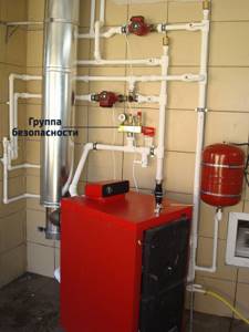
A safety group in a heating system is a control and measuring unit designed to remove air masses and automatically prevent emergency situations associated with an increase in pressure in the heating system to critical values. The safety group is used exclusively in closed heating systems. In an open type CO with natural coolant circulation, it is simply not needed: the air is discharged through an expansion tank located at the top of the system, and the pressure, even under the most extreme conditions, cannot approach at least 1 bar.
The average cost of a ready-to-install unit is 1,100-3,000 rubles; if desired, you can assemble it yourself by purchasing all the components separately.
What is included in the heating system safety group
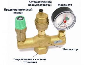
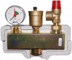
Composition of a classic security group.
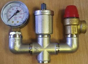
The safety group consists of three elements connected by a collector (a technical element that divides the flow into several parallel branches).
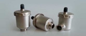
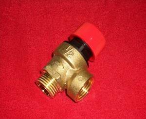
Automatic air vent
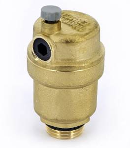
The automatic air valve is designed to relieve air masses from the heating system. An earlier alternative is Mayevsky’s manual taps on radiators. The air in the pipes and radiators of the heating system slows down the heating and circulation rate of the coolant, reduces efficiency, and when heated above 90°C, it seriously increases the pressure, which can lead to damage and depressurization of the heating system.
Air may appear even with competent and careful operation of the CO. The most common reasons:
- initial filling of the heating system with coolant allowing air;
- release of air bubbles when heating water used as a coolant above 90°C;
- improper use of the make-up tap;
- wear of the elements and components of the heating system, which violates its tightness.
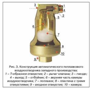
The automatic air vent does not require adjustment or human intervention. As soon as air forms in the system, it enters the air vent channel. The float located in this cylindrical channel lowers, lowering the locking rod: the valve opens and bleeds all the air from the channel.
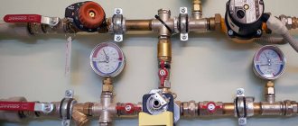
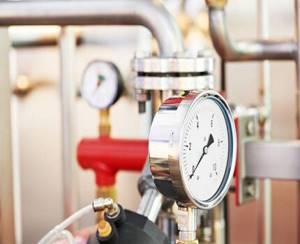
Pressure gauge
The purpose of the pressure gauge is to display the exact pressure inside the heating system to monitor performance. Typically, bars are used as units of measurement. Having adjusted a certain level of pressure, looking at the pressure gauge, you can make sure that the system is working properly, all components are completely sealed, and other elements of the safety group are performing their functions.
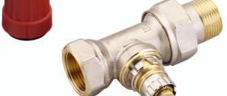
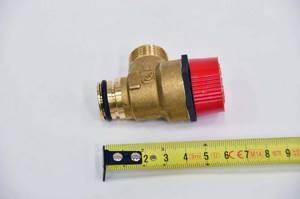
Safety relief valve
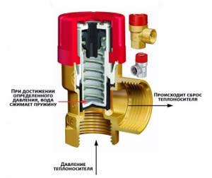
The operating principle of a spring safety valve designed for an individual heating system.
The safety valve ensures automatic release of air, steam or coolant when a critical point is reached, thereby freeing up space in the system for further expansion of the coolant. An increase in pressure in the heating system can be caused not only by the formation of air (which is handled by the air vent), but also by the expansion of the coolant itself during strong heating, which can lead to damage and leakage.
If radiators and pipes can usually withstand a pressure of 7-9 bar without problems, then the most vulnerable element of the heating system is the boiler heat exchanger, often designed for 3 or even 2 bar.
It is based on the maximum permissible operating pressure that the safety valve is selected: there are models designed for a specific pressure and models with an adjustable value, which is set during installation and configuration. The most common and best in terms of price-quality ratio is the spring mechanism, which is what is used in almost all versions of security groups.
The principle of operation of a spring safety valve is the balance of pressure inside the system and the clamping force of the valve spring:
- from the inside, the coolant exerts pressure on the valve shutter;
- on the other hand, the spool is pressed by a rod, on which a spring presses, thereby holding the valve in the closed position;
- as soon as the pressure in the system exceeds a critical value, it outweighs the clamping force of the spring and the valve opens slightly, releasing excess air, steam or coolant;
- as soon as the pressure drops below a critical point, the spring force is sufficient to move the valve to its original closed position.
Security block design
The main reasons for a malfunction in a closed boiler system are increased pressure or excessive filling of the pipeline with coolant, i.e. water. The boiler heat exchanger is the first device to react to such deviations, which is why it fails.
Why might an accident happen?
To prevent such failures in the heating system, a safety unit is used. With its help, the required coolant pressure is achieved in the boiler, pipeline and batteries.
At the moment of excessive pressure, the excess heated coolant is discharged. Emerging emergency situations, such as overheating of a water heating boiler, lead to an increase in pressure in the line. This process is a consequence of exceeding the temperature norm of the coolant.
When heated, the liquid tends to expand, which a closed-type heating system is not designed for - an expansion tank is included in its circuit as an additional reserve. However, its volume is also limited.
Any heating system is under pressure. For low-rise buildings, correctly installed devices that provide coolant create a pressure of 1-2 bar during heating and cooling cycles
The consequence of increased pressure is failure of boiler elements or rupture of the line. To control the pressure and, in the event of a potentially dangerous situation, adjust it to the optimal value, you will need a mounted safety group.
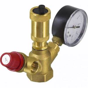
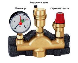
Structurally, the device is formed from the following modules: automatic air vent, pressure gauge and safety valve. All these devices are mounted in a galvanized steel housing with threaded connectors, with or without thermal insulation.
Automatic air vent
In most cases, the automatic air valve for a security system is made of brass.
Air bubbles in the heating system appear due to the following factors:
- initial filling of the heating line with liquid;
- installation of poor-quality or worn rubber seals;
- blockage with corrosive deposits inside the pipeline;
- water replenishment;
- incorrect installation or commissioning of the heating system, etc.
The water entering the heating circuit contains a lot of oxygen, which, when heated, begins to expand, forming air pockets. Due to their formation, the pressure increases and the coolant circulation rate slows down.
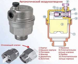
The automatic type of air vent has a special design of the air chamber: dirt particles cannot get inside, and due to the large volume of the air chamber, the problem of blocking the air duct is eliminated
To prevent this from happening, it is advisable to install an automatic air release device, which is easy to use - it does not require adjustment with human intervention.
The principle of operation of the device depends entirely on the design features. The automatic device consists of a channel and a valve. The second element is responsible for removing excess air. If there is no excess pressure in the pipeline, the float is in the raised position, and the needle valve is in the “closed” position.
At the moment an air lock forms, the float will lower and the rocker arm will open the valve - this is how air is released from the system. After removing the excess, the float will return to its original position and the valve will be closed again.
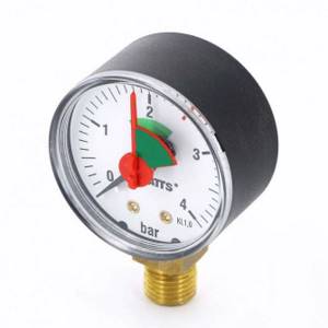
Pressure gauge - an accurate indicator of pressure
The operation of the pressure gauge is designed to measure pressure in the heating system. This device was created to quickly obtain, check and adjust the acceptable level of indicators. Its main characteristic is the determination of accurate data.
In second place is the quality of reliability. For some, the size of the dial is also important for ease of viewing readings. Each pointer mechanism has its own measurement inaccuracy. This error is scattered as follows: at the edges of the scale it has a maximum value, in the center it has a minimum.
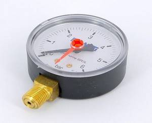
The pressure gauge has two arrows: red and black. The first indicates real data, the second is set to a point that is critical for the system
For each heating mechanism, the accompanying documentation specifies the maximum permissible pressure level that it can withstand. Bars or atmospheres are used as measuring units in pressure gauges. However, the first measurement option has become widespread.
Bars have an intermediate meaning and are as close as possible to the physical and technical atmospheres:
- 1 bar = 10.197 m of water column or 0.1 MPa
- Technical atmosphere (1 atm) = 10 m water column
- Physical atmosphere (1 atm) = 10.33 m water column
An indicator of 1.5 atmospheres is the standard pressure value in pipelines of independent heating systems. Therefore, for an autonomous boiler room, a pressure gauge with a maximum (end of the scale) of 4 atmospheres will be sufficient.
The maximum pressure for which the pressure gauges are designed is 10 atmospheres. Also on the market are devices for 8, 6 and 4 atmospheres
Features of Safety Valve
In a heating system, the safety valve plays an important role. This is a protective device designed for heat generators. The main function is to eliminate loads (drops) when unplanned situations arise. This problem is most pressing for steam-type heating systems.
However, high blood pressure can also occur due to the following problems:
- Due to a malfunction of the automation, the volume of coolant may exceed the permissible limit.
- Rapid increase in temperature in the circuit.
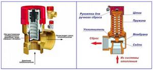
This device also tends to regulate the flow of coolant in the heating line. This is a stamped structure consisting of a brass body equipped with two parts - a membrane and a steel spring. As a rule, at the moment the fuse trips, about 100 g of heated liquid must be eliminated to normalize heating operation.
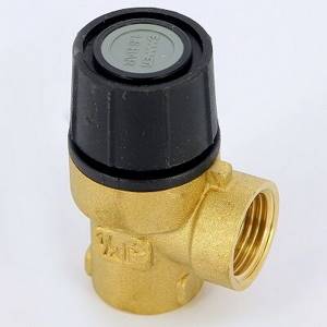
The brass safety valve can withstand coolant temperatures up to 120 °C. The rod and coil spring in this device are made of stainless steel
Due to the flexibility of the first element, the required pressure coefficient acting on the membrane is established. Consequently, the membrane partition blocks the passage to the outside. By changing the degree of compression of the spring in the safety valve, the functions of the safety mechanism in the heating system are regulated.
It is necessary to adjust the protective mechanism in such a way that the maximum possible pressure is 15% greater than the working pressure. The valve adjustment process is carried out every year on the eve of the heating season.
The functionality of the device is checked by forcing it to open. This should be done at certain intervals so that the reset mechanism does not become clogged with various deposits while in a non-working position.
When checking the functionality of the safety valve, the forced release of the coolant is performed using a special handle. An arrow on the device body indicates the direction of hot air exit.
The following article will introduce you to the features of the operation and installation of a safety valve for a boiler, in which the device is disassembled in detail and installation diagrams are provided.
Trigger algorithm
Let us briefly summarize the principle of operation of the entire group. From the very beginning of commissioning, an automatic air vent operates, removing all air from the system. However, if it overheats and reaches critical pressure levels, it is powerless. To avoid an emergency, the safety valve is activated, releasing excess coolant, thereby reducing the pressure in the system.
To monitor the operation of the system, the safety group includes a pressure gauge that shows the pressure at the moment: low pressure indicates depressurization, a malfunction of the expansion tank or make-up valve; increased - about expansion of the coolant or excessive release of steam due to overheating.
Group device
Any safety group for heating consists of three elements installed on one inlet fitting (console). We look from left to right: pressure gauge (pressure sensor); excess air removal device, emergency relief valve (safety valve). On more expensive models, additional elements are installed - temperature meters and a mixing unit.
Below you can find out more about each element.
Air vent
As a rule, the heating system operates at high temperatures. Due to the heating of the liquid in the pipes, various types of gases are released. To prevent the formation of high pressure in the system, as well as to ensure better thermal conductivity, an air vent is used. This mechanism removes any gas generated during equipment operation from the system. In addition, the liquid in the heating system can react with aluminum parts of the equipment, which in turn leads to an active chemical reaction with significant formation of gaseous substances. Also, automatic removal of gases and air from the system will prevent the occurrence of air locks.
System safety valve
The operation of a heating system is always associated with the risk of high pressure in the system. Under significant load, the weakest element of the system fails. To prevent such a situation, a safety valve is provided in the boiler safety group. This element is set to a certain pressure; when this threshold is exceeded, it is triggered. The valve opens and excess fluid leaves the system, thereby normalizing the pressure. The fuse is an essential element in protecting equipment from damage caused by overpressure.
Pressure gauge
To regulate the pressure in the heating line, as well as to visually display this parameter, a pressure gauge is used. In private homes, a device designed for pressure up to 3 atmospheres is mainly used. The pressure parameters of this device should be 1 unit higher than the heating boiler itself. The pressure gauge panel consists of 2 arrows, one of them indicates the working pressure, the other (red) indicates the critical pressure. It is by adjusting the red arrow that the pressure limit in the heating safety group is set.
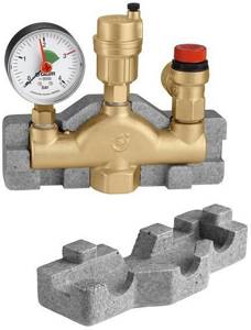
Collector
The group layout is implemented on a special part, which is usually made in the shape of a trident. An air duct is connected in the middle of the collector. This ensures that air and the system can drain freely. The remaining elements of the group are located on the sides.
How to choose a security group for the heating system of a private home
Choosing the right model is not difficult, you need to look at:
- The maximum permissible system power (kW) for which the unit is designed. Typically this is 44, 50 or 55 kW. If the system has less power, great, but if it has more power, you need to look for a more durable option.
- Safety valve response pressure . As a rule, valves with a fixed value are installed in finished units - 1.5 bar, 3 bar, 4 or 6 bar. The response pressure must correspond to the maximum permissible operating pressure of the most vulnerable element of the heating systems - usually a steel boiler heat exchanger designed for 2 or 3 bar. Safety valves for 2 bar, despite sufficient demand, are difficult to find on sale; the way out of the situation is to assemble the unit yourself by purchasing the safety valve and other elements separately (see below for more on this).
- The operating temperature is the permissible temperature of the coolant; for almost all modern models it is within the range of -10°C – 110°C, which is more than enough.
- Compatibility with coolant - if antifreeze is used as a coolant instead of water.
- Threaded connection diameter – it can be 1″, 1/2″ or 1.4″ in diameter. You can also select a unit that does not match the thread diameter, but then you will have to take care of selecting an adapter, which is not always easy.
It is important to pay attention to the material of manufacture; galvanized steel or stainless steel is a good, but not the best option. More expensive, but more durable, wear-resistant and even more resistant to corrosion are brass products. The material of manufacture is not always indicated in the characteristics; in addition, the collector can be made of steel, and the remaining elements - of brass. You can distinguish brass by its characteristic monochromatic, matte color (bronze-golden or silver, depending on the alloy).
How to choose a room thermostat and save up to 30% per month on heating
Assembling the security unit yourself
There shouldn't be any difficulties in making the safety unit.
To start the process, you will need to prepare the following modules and tools:
- relief valve;
- pressure gauge;
- air vent;
- wrench;
- gas keys;
- two squares with a threaded connection of external and internal type;
- union;
- crosspiece;
- adapters;
- sealant;
- sanitary flax for sealing and sealing joints.
Initially, the squares must be screwed into the crosspiece. For a tight connection, the flax strands are wound onto the threads in a clockwise direction, and the distribution of the sealant over the surface should be the same.
The cost of a self-made safety unit for a heating system is approximately two times less than analogues offered on the market
A thin layer of sealant is applied on top of the threads. Next, using a wrench, screw the squares into the crosspiece perpendicular to one another.
Now you need to install the pressure gauge, safety valve and air vent. If parts have different diameters, appropriate adapters are used. After the final assembly of all modules, the operation of the mechanism must be checked under pressure - the device should not leak, and all parts should be in working condition.
The best known manufacturers and models: characteristics and prices
TIM JH-1024-1.5
One of the most inexpensive but proven models. Despite the low cost, it has a brass manifold. The maximum power of CO is 50 kW, the response threshold of the safety valve is 1.5 bar, the connection diameter is 1″ BP. Country of origin: China.
VALTEC VT.460.0
One of the best ready-made safety groups for the boiler and heating system of the famous Italian manufacturer VALTEC. The unit is entirely made of nickel-plated brass and has an additional threaded outlet for connecting an expansion tank. It is distinguished by high reliability and quality of all connections and technical elements. The permissible power of the CO is up to 44 kW, the response threshold is 3 bar, the diameter of the connection to the network is 1 V.
Watts KSG 30
Security group of another well-known German company with production in Italy. There is a whole range of models on the market, where there are models designed for power up to 100 and even up to 200 kW. The collector body is made of galvanized steel, which, given the cost, is a disadvantage. However, the technical elements are made of brass, and there is a thermal insulation casing. Maximum CO power – 50 kW, response pressure – 3 bar, connection diameter – 1″ (internal thread).
Caleffi 302631
Another reliable and high-quality (in terms of materials and assembly) Italian-made model, entirely made of brass, with a heat-insulating polystyrene casing included. The maximum power of the CO is 50 kW, the response pressure is 3 bar, the diameter of the threaded connection is 1″ female.
Cost: 4,500-4,750 rubles.
Prices: summary table
| Manufacturer and model | Maximum CO power, kW | Response pressure, bar | Thread diameter, inch | price, rub. |
| TIM JH-1024-1.5 | 50 | 1,5 | 1″ BP | 990-1 200 |
| VALTEC VT.460.0 | 44 | 3 | 1″ BP | 1 650-1 800 |
| Watts KSG 30 | 50 | 3 | 1″ BP | 2 600-3 400 |
| Caleffi 302631 | 50 | 3 | 1″ BP | 4 500-4 750 |
Where is the security group placed?
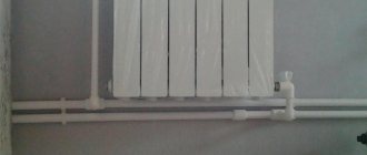
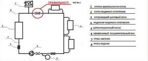
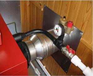
The safety group is placed on the supply line of the heating boiler, as close as possible to the boiler unit, but above its level. It is prohibited to install any shut-off valves, filters or other elements that narrow the pipeline between the boiler and the safety group. The safety group must be installed strictly in a vertical plane so that the air vent and safety valve are in a vertical position; in the horizontal plane the unit can be rotated as desired.
Please note that if there is an appropriate outlet pipe, it is recommended to connect the expansion tank through it. If this is not done, the outlet pipe for the expansion tank must be plugged.
Connection diagram
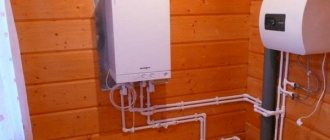
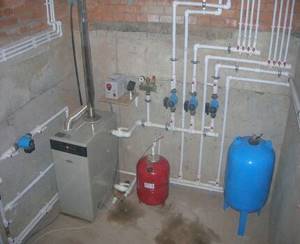
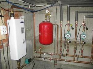
A floor-standing boiler, unlike a wall-mounted one, does not have a built-in circular pump, an expansion chamber or a safety group. All this needs to be installed outside it. The supply pipe is connected to the top of the boiler and the safety group is mounted there.
There should be no shut-off valves, filters or other elements between the boiler and the safety group. For example, if the tap is closed, an accident will occur.
Note! The safety group is always mounted only in a vertical position and above the boiler. The security group can be presented in a corporate form
The main element in it is an emergency valve that relieves pressure. In some cases, instead of the entire safety group, it is possible to install only one emergency valve on the tee
The security group can be presented in a corporate form. The main element in it is an emergency valve that relieves pressure. In some cases, it is possible to install only one emergency valve on the tee instead of the entire safety group.
Very often, a safety group is placed immediately above the boiler, and at the moment the pressure is released by the valve, liquid enters the boiler, which is unacceptable if it is electric. Therefore, if the safety group is installed above the boiler, then a tube is connected to the emergency valve and taken to the side. A container for liquid is placed under it.
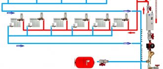
Connection diagram for a safety group in a heating system with an expansion tank
The return circuit is carried out as follows (in the direction from the boiler) - a shut-off valve, a circulation pump, a dirt filter, a second shut-off valve, a tee with a valve for connecting the expansion tank and a valve for filling the network. For systems with such a simple circuit, installation of a check valve is not required. The dirt filter is mounted with an oblique outlet downwards. The pump rotor must be horizontal and the terminal box in the upper position.
Note! The expansion chamber must not be installed in front of the first shut-off valve. Expanzomat compensates for pressure fluctuations in the heating system
When water heats up, it expands. To prevent pressure from being released through the emergency valve, the expansion tank reduces it. The volume of the expansion chamber must be at least 1/10 of the entire system
The expansion valve compensates for pressure fluctuations in the heating system. When water heats up, it expands. To prevent pressure from being released through the emergency valve, the expansion tank reduces it. The volume of the expansion chamber must be at least 1/10 of the entire system.
For example, if the boiler volume is 80 l, and the heating system is 140 l, then the total volume is 220 l. Therefore, an expansion tank of 22 liters is required for stable operation. Experts recommend taking a larger expansomat - 1/7-1/8 of the volume of the entire system.
Expansion tank in a closed heating system
As a sealant for threaded connections, it is recommended to use FUM tape, flax, pastes or other sealing agents that will ensure a tight connection of all elements even during heavy loads.
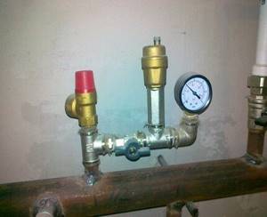
Connection to the heating system
The entire process of connecting the safety group to the heating system consists of a threaded connection to the vertical pipe previously allocated for it (the diameter of the pipe thread = the diameter of the thread of the safety group) and checking the functionality of its modules. An example of installing a security group is shown in the diagram below.
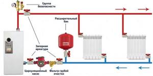
An example of installing a security group in a closed heating system.
After a tight connection, you need to check the operation of the air vent by forcibly opening it: turning the valve handle (top cap) until it clicks. Leave the air vent open. It is better to close the automatic air vent while the system is filling with coolant. A drain tube must be placed on the relief valve, leading either to the floor (into a prepared container) or to the sewer. In the first case, the consequences of the accident will be visible; when draining into the sewer, you may not even know what happened.
Operating principle of the safety unit
The security group works according to an extremely simple scheme, where each of the modules is responsible for maintaining the standards of certain indicators in a private boiler room:
- Thanks to a convenient pressure gauge, the user can monitor the pressure readings at the moment the line is filled with coolant, as well as during the operation of the boiler.
- The safety valve protects the heat generator from critical pressure drops.
- The main functionality of the air vent is based on the automatic release of air entering the pipeline during its initial filling or during operation.
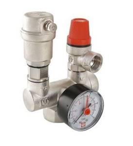
All safety modules are represented by a single unit and are equipped with a special housing - a manifold.
Provided that the boiler room circuit uses an open type expansion tank, installing a safety group does not make sense - the pressure in the pipeline is equal to atmospheric pressure, and excess air leaves the system through the tank capacity.
Regardless of the type of boiler used (solid fuel, gas, diesel), the protective unit is considered the main emergency element of a closed heating system, which tends to work with excess pressure
How to properly assemble a knot with your own hands
A correctly configured safety group should be in the shape of a trident, so that the air vent is located in the middle, directly above the pipe under the safety group. This way air will be guaranteed to flow into it, without any obstacles.
A homemade security group includes the following elements:
- pressure gauge, automatic air vent and safety valve;
- 2 steel or brass squares at 90° with external and internal threads (the diameter is selected to match the diameter of the threads of the modules and the crosspiece);
- 1 steel or brass cross;
- 1 coupling/nipple for connecting the finished unit with the heating system tee;
- tow or silicone for sealing joints (FUM tape is not recommended because it deforms at temperatures above 70-80°C).
We connect the elements in accordance with the photo below, connect them to the heating system and check their functionality.
An example of a knot assembled by yourself.
Why is it needed and how does it work?
Any heating system operates within a certain range of pressure values. It changes depending on the degree of heating and cooling of the liquid in the network. When the coolant heats up, it expands, thereby increasing the pressure in it.
A safety group is needed to prevent rupture of pipes, leaks from shut-off valves, or breakdown of other elements of the heating system due to high pressure. With its help, the pressure is controlled, and when its maximum permissible value is reached, it discharges the required amount of coolant from the network.
A security group consists of the following elements:
- Emergency (safety) valve;
- Automatic air vent;
- Pressure gauge.
Heating safety group diagram
All of them are attached to one base - the console. The connection between the console, the emergency valve body and the air vent is made by hot forging. The rotary cover on the safety valve is made of heat-resistant nylon.
There should be no air in any heating systems. Because of it, noise occurs in the network, and some elements of the network, for example, a circulation pump, fail faster. The entry of air into the heating system is inevitable when it is filled with coolant.
It is also released from liquids when they are heated to high temperatures. In order to remove it from the system, automatic air vents are used.
Using a pressure gauge, visual control of the pressure in the network is carried out. The emergency valve releases coolant from the system to reduce pressure. The direction of liquid discharge is shown by an arrow on the device body. This is necessary so that during the release of the coolant it does not fall on a person.
It is best to connect a plastic tube to the safety valve and lead it to the container. This will not only make its use safer, but will also help you monitor its operation and check how much coolant has been discharged and whether it is in working condition.
The air vent is an important part of the heating safety group
If the valve has been inactive for a long time, it may begin to leak due to contamination, thereby reducing the pressure in the network. Therefore, it needs to be cleaned periodically. To open the valve, turn the cap in the direction of the arrow.
Note! The drain hose is selected with the same diameter as the outlet on the emergency valve so that it does not create obstacles during the release of coolant from the heating system.
Maintenance
- It is advisable to check the status of all modules of the security group every 2-3 months.
- The safety valve must be cleaned every 6 months to prevent leaks and contamination. To do this, it must be opened by turning the valve cap in the direction of the arrow.
- After 5-7 operations, it is recommended to replace the safety valve due to wear on the spring, which can lead to leakage and operation at lower pressures in the system.
Instructions Boilers Boiler room equipment Safety valves
Security system for closed type heating - operating principle of devices
Any emergency unit is assembled in one housing, which simplifies installation and increases its reliability due to fewer butt connections.
Typically, the unit is supplied disassembled, that is, the console is located separately, onto which the exhaust valve, air vent and pressure gauge are then attached. Let's look at what a security group is and what it's made of.
Rice. 2 Operating principle and design of exhaust valves
Drain valve
The drain valve has a simple design and consists of a body and a spring-loaded shutter element, covered with a protective cap on top.
When the pressure in the system increases due to the expansion of the heated liquid, it puts pressure on the valve lock. It rises up and the coolant flows freely through a channel located perpendicular to the connecting pipe.
Some devices have a rotating hood that allows you to open the outlet manually. Typically, exhaust valves have internal (IF) or external (M) threads on the connection pipe. In addition to a threaded notch, the side outlet can be made in the form of a herringbone-type fitting for connecting a flexible hose.
The main material used to manufacture the vast majority of exhaust valves is brass. The widespread replacement of metals with polymers also affected this type of fittings - in the retail chain there are devices made from heat-resistant plastics.
In the technical specifications, exhaust valves are indicated by two main parameters: their response pressure (for domestic heating systems, usually 3 - 5 bar) and the nominal diameter of the connecting and outlet pipes in inches or millimeters. Typical sizes are 1/2 (12.7 mm), 3/4 (18 mm) or 1 inch (25.4 mm).
Typically, the manufacturer does not indicate the upper temperature threshold for the operation of devices, so it is useful for the consumer to know that, according to state standards, fittings made of non-ferrous metals for water supply and heating can operate at temperatures of the working environment up to 200 °C.