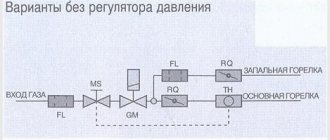
Purpose and types
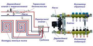
A warm water floor is distinguished by a large number of pipe circuits and a low temperature of the coolant circulating in them. Basically, heating the coolant to 35-40°C is required. The only boilers that can operate in this mode are condensing gas boilers. But they are rarely installed. All other types of boilers produce hotter water at the outlet. However, it cannot be run into the circuit at this temperature - a too hot floor is uncomfortable. To reduce the temperature, mixing units are needed. In them, in certain proportions, hot water from the supply and cooled water from the return pipeline are mixed. After which, through the manifold for the heated floor, it is supplied to the circuits.
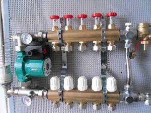
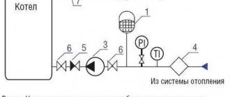
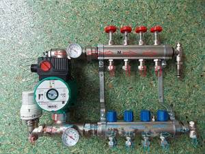
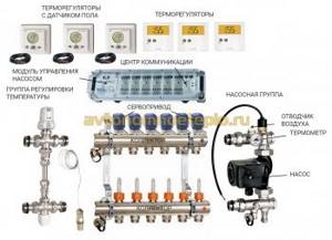
Manifold for underfloor heating with mixing unit and circulation pump
To ensure that all circuits receive water at the same temperature, it is supplied to a heated floor comb - a device with one input and a number of outputs. Such a comb collects cooled water from the circuits, from where it enters the boiler inlet (and partially goes to the mixing unit). This device - supply and return combs - is also called a manifold for heated floors. It can come with a mixing unit, or maybe just combs without any additional “load”.
Materials
The manifold for heated floors is made of three materials:
- Of stainless steel. The most durable and expensive.
- Brass. Average price category. When using high-quality alloy, they last a very long time.
- Polypropylene. The cheapest. For working with low temperatures (as in this case), polypropylene is a good budget solution.
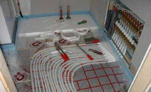
Manifold for underfloor heating with 6 circuits
During installation, the inputs of the heated floor circuits are connected to the supply comb of the manifold, and the loop outputs are connected to the return comb. They are connected in pairs to make adjustments easier.
Equipment
When installing a water heated floor, it is recommended to make all contours the same length. This is necessary so that the heat transfer from each loop is the same. It’s just a shame that this ideal option doesn’t come around very often. Much more often there are differences in length, and significant ones.
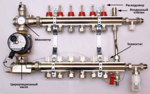
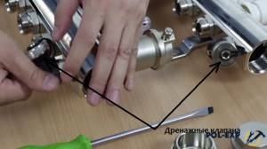
To equalize the heat transfer of all circuits, flow meters are installed on the supply comb, and control valves are installed on the return comb. Flow meters are devices with a transparent plastic cover with printed graduations. There is a float in the plastic case, which marks the speed at which the coolant moves in a given loop.
It is clear that the less coolant passes through, the cooler the room will be. To adjust the temperature regime, the flow rate on each circuit is changed. With this configuration of the manifold for heated floors, this is done manually using control valves installed on the return comb.
The flow rate is changed by turning the knob of the corresponding regulator (they are white in the photo above). To make it easier to navigate, when installing the collector unit, it is advisable to sign all the circuits.
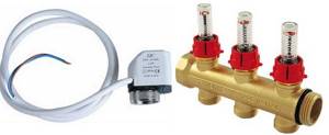
Flow meters (right) and servos/servos (left)
This option is not bad, but you have to regulate the flow rate, and therefore the temperature, manually. This is not always convenient. To automate the adjustment, servo drives are installed at the inputs. They work in tandem with room thermostats. Depending on the situation, a command is sent to the servo drive to close or open the flow. In this way, maintaining the set temperature is automated.
How to adjust the Valtek floor heating comb
VALTEC SrL was founded in Italy in 2002 and specializes in the production of equipment for thermal systems operating in difficult conditions. Currently, it is highly respected among consumers in various countries, including Russia. In terms of price, it is considered affordable for most users and fully meets European quality standards.
Valtec underfloor heating manifold with rotameters
The parts are made of CW617N brass and AISI 301 stainless steel. The manifolds have adjustment and shut-off valves, drain valves, and automatic air vents. All seals are made using EPDM rings, the standard for connecting Euroconus pipe loops. Some models have additional equipment that allows you to fully automate the operation of the devices. The number of outlets ranges from 2 to 12, diameters 1″ and 1 1/4″. The warranty on all company equipment is 7 years, maximum operating temperature is +120°C, optimal pressure is 10 Bar.
The devices are used to lower the temperature of coolants at the entrance to the floor heating system by mixing hot (inlet) and cold (outlet). At the same time, the device regulates the volume of water supplied to each individual circuit of the system. In this case, it is possible to regulate the temperature of the floor heating both in several circuits of one room, and in rooms separately, taking into account their purpose.
Main elements of the collector
Design of VALTEC collectors
Depending on the specific model, the technical parameters of some elements may vary; there are options with additional equipment to improve performance.
Fittings and bodies are made of hot-formed brass, brackets are made of galvanized steel, valve gaskets and O-rings for connections are made of ethyl-propylene elastomer. For the manufacture of springs operating in difficult conditions, special high-alloy steel, decorative caps, handles and flow meters made of acrylic butadiene styrene are used. When connecting several manifolds together, it is recommended to use the original manufacturer's double self-sealing nipple. Manifolds can be equipped with control valves with or without position locking.
VALTEC manifold assembly procedure
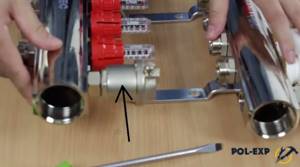
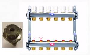
The device is sold in packaging; before starting work, carefully read the manufacturer’s instructions. The supply manifold on the side has a red mark, the reverse is blue. During connection, ensure that all pipelines of the floor heating system are connected correctly. Flow meters are installed on the supply manifold at the factory, and manual shut-off valves are installed on the return manifold.
Step 1: Remove two automatic air vents, two shut-off valves, two plugs and two drain valves from a plastic bag. Please ensure that all parts have seals.
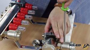
Step 2 . Use a screwdriver to unscrew the screws and remove one of the mounting brackets, tighten the shut-off valves. They are screwed into the ends of the collectors on one side for hot water, and on the other for “return”.

Unscrew the screw and remove the mounting bracket
Step 3. Screw automatic air vents into shut-off valves. Opposite them, screw two drainage valves to the bottom of the collectors.

Tighten shut-off valves
Screw automatic air vents to the valves
Screw on 2 drain valves
Step 4. Install plugs at the ends and replace the previously removed bracket.
Replace the bracket
Assembly is complete, the VALTEC manifold block is ready for use. If necessary, you can move automatic air vents with drain valves from one side of the manifold to the other. Such a need may arise due to the characteristics of the heating system and the existing cold and hot water supply circuit. The manufacturer allows you to swap the collectors, installing the hot coolant inlet at the top and the cold coolant outlet at the bottom.
To increase comfort, servo drives can be mounted on the collector. The device is controlled using a room thermostat or a programmable chronothermostat. The latter allows you to set the temperature by day of the week and hour of the day. The pipes are connected to the manifold using Eurocones with seals,
Important. The collector should always be located above the floor heating or space heating system. Otherwise, the air removal valves will not work.
Production of the company
When choosing a specific model, take into account all the technical characteristics of the heating system. If it is difficult to navigate on your own, then it is better to seek help from professional specialists.
The microclimate in the room and the uniformity of floor heating in different areas depend on the correct adjustment of these devices. In addition, by adjusting flow meters, it is possible to significantly reduce energy losses for heating buildings. And this is very important, given the current cost of electricity and gas.
Inexperienced installers believe that in order for the temperature of the circuits to be the same, the readings of the flow meters must also be at the same level and thus they are adjusted.
Inexperienced installers set everything up “on a ruler”, believing that the flow rate is the same everywhere
This is wrong, if this were actually the case, then why would we need devices that are quite complex from an engineering point of view? Pipes of different lengths must receive different volumes of coolant, only in this case their temperature will be the same. Accordingly, the flow meter readings on each loop are individual.
Flow meter readings on each loop are individual
There are several ways to configure flow meters.
First way
The most correct, fast and accurate. The adjustment must be made taking into account the parameters of the hydraulic resistance of each circuit. For this purpose, VALTEC has developed a special program, which can be used on the website of the official representative. Working with the program is very simple, fill out all the tables with your data and eventually get the resistance of each loop. The only inconvenience is that the results are given in kilograms per second, while the scale on the flow meter is in liters per minute. In order to use the flow meter scale, you need to multiply the obtained data by 60. Set the flow meter scale for each loop according to the obtained values in turn.
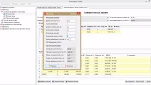
Hydraulic calculation program
Second way
It is used in cases where the cheapest manifold without flow meters with a scale was purchased. Instead, conventional control valves are installed; the flow rate is changed by turning them clockwise or counterclockwise.
Manifold with control valves
It is recommended to install the flow meter on the “return”; they are not adjustable, but do have a scale. Turn the tuning valve and monitor the actual flow rates using the return scale.
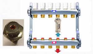
Flow meter installation diagram
If for some reason it is impossible to install flow meters on the “return”, then you should use the table supplied with the manifold. It indicates the change in the amount of coolant depending on the number of turns of the control valve. The calculation program gives the values as percentages; you need to find this parameter in the table, so you can find out how many turns to tighten or unscrew the valve. This method is more complicated, but it allows you to save money when purchasing a collector.
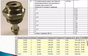
The required values in the table are marked with a tick
Third way
In scientific terms it is called empirical, but in simple terms it is called “by eye”. It requires knowing the actual length of each loop. Adjustment should begin with the longest one.
Open the valve regulating this loop to maximum. Next, make calculations as a percentage of how much each of the remaining loops differs from the longest one and reduce the clearance of the control valve by the same percentage. This is a preliminary adjustment; later adjustments must be made depending on the actual temperature of the loops. The process may take several days; the floor heating system is very inert and it is impossible to immediately notice a change in its temperature.
The end result is to achieve the same coolant temperature at the return of each loop.
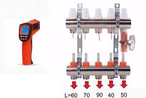
To measure, you can use a clip-on thermometer or a more modern pyrometer
We will give some professional answers to pressing questions from inexperienced installers.
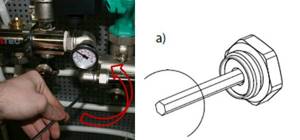
How to adjust the balancing valve (flow meter)?
Work must be performed with the circulation pump turned on for each loop separately. Changing the flow rate of the coolant is achieved by adjusting the nominal diameter of the passage, while leveling out the difference in hydraulic resistance in loops of different sizes.
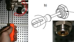
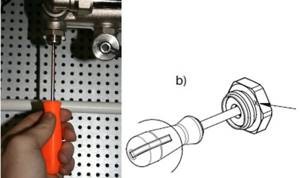
Step 1: Remove the red thermowell from the valve. It is secured with latches and can be removed by lifting it up.
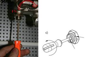
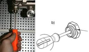
Step 2: Use the top bushing to completely close the valve. In this case, the feed indicator should be set to zero.
Step 3. By smoothly turning the control sleeve, set the flow meter values according to the calculated values.
Step 4. Using the white lower sleeve, secure the selected position. The lower bushing serves as a locknut.
Step 5: Replace the protective sleeve.
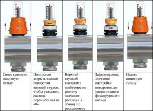
Valve balancing with detent
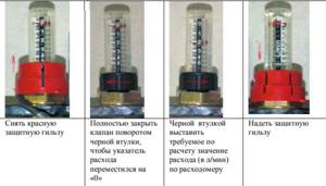
Valve balancing without locking
How to change the setting valve?
This element is considered the most loaded, which causes the unit to fail. You need to fix the problem in the following order:
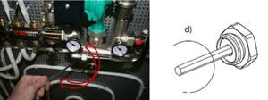
- Unscrew the valve from the manifold using an adjustable or open-end wrench. In this case, the key must be inserted into a special brass nut;
- remove the valve and inspect it carefully. If dirt or solid particles are found, clean all elements. Screw the valve back and check operation. If the device cannot be restored, replace it with a new one;
- To replace the transparent plastic bulb, it must be unscrewed by hand.
In most cases, such actions can completely restore the functionality of the factory element.
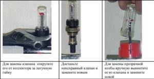
Steps to follow when repairing a tuning valve
How many collectors are needed to heat the floors of a two-story house?
Due to significant differences in floor heights and large distances between individual circuits, manufacturers recommend installing separate collectors on each floor. In this case, it will be necessary to specifically calculate the pump power depending on the value of the total resistance of the loops to liquid flows.
Which pipes should be connected to VALTEC manifolds?
The company produces two types of pipes: metal-polymer and suture polyethylene with an upper diffusion layer. The former are considered the best option for underfloor heating systems. The latter are recommended for use during the installation of low-temperature systems; they are cheaper, but require an increased number of fixation points and are not designed for high operating temperatures.
Valtec floor heating pipe
Why does the temperature of the water supply to the circuit not rise above +38°C, but the thermal head is more than 40°C?
The mixing unit for VALTEC collectors mixes two coolant flows - hot from the boiler and “return”. Make the ratio adjustment with the balancing valve. If the “return” is too cold or there is a lot of it in volume, then adjust the balancing valve, due to this the temperature of the water supplied to the circuit will rise.
Is it possible to increase the number of loops of the collector block by attaching an additional one?
It is possible, the technical parameters of VALTEC collectors allow this. But you need to take into account the maximum power of the circulation pump; if it is not enough, then you need to install a more powerful one.
Should corrugated pipes be used for protection during installation of underfloor heating systems?
No, you shouldn’t do this; there will be great difficulties with adjusting the VALTEC manifolds. Corrugated pipes may only be used at the points where the system is connected to the collector, and then only in exceptional cases.
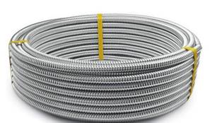
Corrugated stainless steel pipe
Is it possible to make radiator heating without collectors?
This scheme was previously used in all houses; today the performance indicators do not satisfy consumers. Connecting to the collector system allows you not only to automatically maintain a comfortable microclimate in the premises, but also to save significant money during the heating season.
How to check the tightness of connecting all elements to the manifold?
According to the current regulations SP 41-102-98, a leak test is performed after filling the system and under pressure 1.5 times higher than the working one. In practice, such tests can only be carried out by specialized companies with complex, expensive equipment. And for those who installed the collector themselves, there is a simple way out.
Place clean sheets of paper under all connections; the heating system should function. Wait 15–20 minutes and check the paper; even the slightest leaks will become noticeable. Carefully inspect the suspicious nodes; they are located exactly above the wet paper. Fix the problem using any available method. In most cases, it is enough to just tighten the threaded connection, but sometimes you will have to change seals with mechanical damage or manufacturing defects. The disadvantage of this method is that leaks are detected only at the operating fluid pressure. Although practice shows that this is quite sufficient, the floor heating system is closed, the pressure in it does not depend on the water pressure in the other pipelines and does not have sudden pressure surges.
Pressure testing of water heated floors
Is it possible to change the connection diagram of the pumping and mixing unit to the manifold?
No, you can't install it that way. The collector with warm water should be connected to the unit on the right, and with cold water on the left.
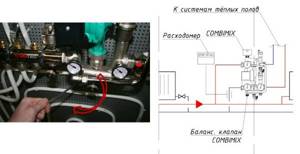
The VALTEC COMBIMIX (VT.COMBI) pump and mixing unit is designed to maintain a given temperature of the coolant in the secondary circuit (due to mixing from the return line). Using this unit, it is also possible to hydraulically link an existing high-temperature heating system and a low-temperature underfloor heating circuit. In addition to the main control elements, the unit also includes the entire necessary set of service elements: an air vent and a drain valve, which simplify the maintenance of the system as a whole. Thermometers make it easy to monitor the operation of the unit without the use of additional devices and tools.
It is permissible to connect an unlimited number of heated floor branches with a total power of no more than 20 kW to the VALTEC COMBIMIX node. When connecting several branches of a heated floor to a node, it is recommended to use VALTEC VTc.594 or VTc.596 collector blocks.
1. Secondary circuit balancing valve (position 2
on the diagram).
This valve ensures mixing of the coolant from the return collector of the heated floor with the coolant from the supply pipeline in the proportion necessary to maintain the specified temperature of the coolant at the outlet of the COMBIMIX unit.
The valve setting is changed using a hex wrench; to prevent accidental rotation during operation, the valve is secured with a clamping screw. Kvτ capacity values
valve from 0 to 5 m 3 / h.
Note: Although the valve capacity is measured in m3/h, it is not the actual coolant flow rate passing through this valve.
2. Balancing shut-off valve of the primary circuit (pos. 8
)
Using this valve, the required amount of coolant is adjusted that will flow from the primary circuit to the unit (unit balancing). In addition, the valve can be used as a shut-off valve to completely shut off the flow. The valve has an adjusting screw with which you can set the valve capacity. The valve is opened and closed using a hex key. The valve has a protective hex cap.
During operation of the heating system, a mode may arise when all control valves of the heated floor are closed. In this case, the pump will operate in a muted system (without coolant flow) and will quickly fail. In order to avoid such modes, there is a bypass valve on the unit, which, when the valves of the underfloor heating system are completely closed, opens an additional bypass and allows the pump to circulate water through a small circuit in idle mode without loss of functionality.
The valve is activated by the pressure difference created by the pump. The pressure difference at which the valve opens is set by turning the regulator. There is a scale on the side of the valve with a range of 0.2–0.6 bar. Pumps recommended for use with COMBIMIX have a maximum pressure of 0.22 to 0.6 bar.
After the heating system is completely assembled, pressure tested and filled with water, it should be adjusted. The adjustment of the control unit is carried out together with the commissioning of the entire heating system. It is best to adjust the unit before starting to balance the system.
1. Remove the thermal head (1
) or servo drive.
To ensure that the control valve actuator does not affect the assembly during adjustment, it must be removed.
2.
Set the bypass valve to the maximum position (0.6 bar).
If the bypass valve is triggered while the unit is being configured, the setup will be incorrect. Therefore, it should be set to a position in which it will not work.
3.
Adjust the position of the secondary circuit balancing valve (item
2 in the diagram).
The required throughput of the balancing valve can be calculated independently using a simple formula:
t 1 –
temperature of the coolant in the supply pipeline of the primary circuit;
t11–
temperature of the coolant in the supply pipeline of the secondary circuit;
t12–
coolant temperature in the return pipeline (both circuits are the same);
Kvτ
is
the control valve capacity coefficient; for COMBIMIX it is assumed to be 0.9.
Obtained Kv
set on the valve.
Initial data: design temperature of the supply coolant
– 90 °C; design parameters of the heated floor circuit are 45 – 35 °C.
Kv value is set on the valve.
4.
Set the pump to the required speed.
To do this, you need to calculate the water flow in the secondary circuit and the pressure loss in the circuits after the unit using the formulas:
where Q
– the sum of the thermal power of all loops connected to COMBIMIX;
c
– heat capacity of the coolant (for water – 4.2 kJ/kg °C; if a different coolant is used, the value should be taken from the data sheet of this liquid);
t
11,
t
12 – temperature of the coolant on the supply and return pipelines of the circuit after the COMBIMIX unit.
Δ P
с – pressure loss in the design circuit of the heated floor (including collectors). This value can be obtained by performing a hydraulic calculation of the heated floor. To do this, you can use the calculation program VALTEC.PRG.
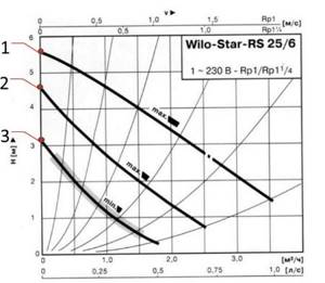
Using the pump nomograms presented below, we determine the pump speed. To determine the pump speed, a point with the corresponding pressure and flow rate is marked on the characteristic. Next, the nearest curve above this point is determined, and it will correspond to the required speed.
Initial conditions: underfloor heating with a total power of 10 kW, pressure loss in the most loaded loop of 15 kPa (1.53 m of water column).
Water flow in the secondary circuit:
Pressure losses in the circuits after the
COMBIMIX with a reserve of 1 m of water.
art.: The pump speed is selected -
MED at the point (0.86 m 3 / h; 4.05 m water art.):
If it is not possible to calculate the pump, then this stage can be skipped and immediately proceed to the next one. At the same time, set the pump to the minimum position. If during the balancing process it turns out that there is not enough pump pressure, you need to switch the pump to a higher speed.
5.
Balancing the branches of the heated floor.
Close the balancing shut-off valve of the primary circuit. To do this, open the valve cover and use a hex wrench to turn the valve counterclockwise until it stops.
The task of balancing heated floor branches comes down to creating the required coolant flow in each branch and, as a result, uniform heating.
The branches are balanced with each other using balancing valves or flow regulators (not included in the COMBIMIX kit; flow regulators are included in the VTc.596.EMNX manifold block). If there is only one circuit after COMBIMIX, then nothing needs to be linked.
The balancing process is as follows: balancing valves/flow regulators on all branches of the heated floor are opened to the maximum, then a branch is selected in which the deviation of the actual flow from the design one is maximum. The valve on this branch closes to the required flow rate. Thus, it is necessary to adjust all the branches of the heated floor.
When adjusting the VT.FLC15.0.0 flow regulators, you simply need to set the desired flow rate on the scale in l/min by turning the knob. If it is not possible to use a flow indicator, then you can balance the branches approximately by heating the floors or by the temperature of the return coolant.
If during the balancing process it was not possible to obtain the required flow rate through the branches even with the valves open, this means that the hydraulic calculation was performed incorrectly and the pump should be switched to a higher speed.
Setting the primary circuit balancing valve
The balancing valve of the primary circuit is adjusted together with the balancing of the rest of the heating system. The essence of balancing a heating system is to adjust the coolant flow through each heating device, including COMBIMIX, exactly according to the design. If heating systems are not balanced correctly, the system may operate when some of the heating devices are overheated and some are not warmed up enough.
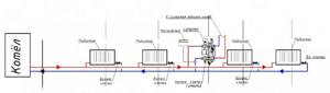
Consider the following diagram of a heating system with a connected COMBIMIX node. This is a two-pipe dead-end heating system with horizontal wiring.
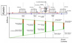
Below the diagram is a piezometric graph. The graph shows the pressure drop in the heating system with green slanted lines. The device located closest to the boiler (or individual heating point) has a greater pressure drop between the forward and return pipelines (vertical lines) than the device located at the end of the system. The orange color on the vertical lines shows the pressure drop across the devices without taking into account the balancing valves, the green color shows the pressure drop that must be created across the valve in order to balance the system. The higher the pressure drop across the device, the greater the flow rate passes through it at the same throughput. In order to equalize the coolant flow in the system, it is necessary to add resistance to devices that are closer to the boiler using balancing valves or control valves. The closer the device is to the boiler, the more resistance must be added using the valve (more valve closing). The graph shows that the valve of the first device is closed so much that its resistance is several times higher than the resistance of the radiator. With the latter device, the valve is practically open and its resistance is low.
Balancing, as a rule, comes down to finding the desired setting of the balancing valves. There are three main ways to perform balancing.
The calculation method consists in the fact that when hydraulically calculating a heating system, a similar piezometric graph is drawn up for the designed heating system. During the hydraulic calculation, the required pressure loss at each balancing valve is determined. Next, the following formula determines the valve capacity:
where V
– volumetric coolant flow rate, m 3 /h;
Δ P
– required pressure loss across the valve, bar.
After calculating the capacity according to the recommendations of the balancing valve manufacturers, the adjuster sets the design capacity value on each valve. Hydraulic calculations must be carried out by a qualified specialist manually or using specialized programs, for example the VALTEC.PRG engineering systems calculation program.
First, let's determine the required coolant flow in the primary circuit. To do this, you can use the following formula:
where Q is the sum of the thermal power of all devices connected after COMBIMIX; c – heat capacity of the coolant (for water – 4.2 kJ/kg °C; if a different coolant is used, the value should be taken from the data sheet of this liquid); t1, t2 – temperature of the coolant in the supply and return pipelines of the primary circuit (the temperatures of the coolant in the return pipeline of the primary and secondary pipelines are the same).
For a heated floor with a total power of 10 kW with a design temperature of the supply coolant of 90 °C, design parameters of the heated floor circuit of 45–35 °C, the coolant flow in the primary circuit will be as follows:
When calculating, the designer determined that the pressure loss on the balancing valve of the unit should be 9 kPa (0.09 bar), in order for the coolant flow in the primary circuit to be 0.159 m 3 / h, the kv of the valve should be:
Next, according to the characteristics of the balancing valve of the primary circuit given below, the number of turns of the adjusting screw is determined.
To determine the number of revolutions, you can not count kv but use the nomogram given below. To do this, plot the required flow through the primary circuit and the required pressure loss across the valve on the graph. The nearest inclined line will correspond to the required setting (number of revolutions). To improve accuracy, you can interpolate the obtained values.
The first line of the table indicates the position, the second line of the table indicates the number of turns of the adjusting screw. (In this example, 2 and ¼.) The third line shows Kv for this setting, as you can see it practically coincides with the calculated one.
Setting the valve speed:
The correct adjustment of the valve should start from the position of the valve being fully closed; using a thin flat-head screwdriver, tighten the adjusting screw until it stops and put a mark on the valve and on the screwdriver.
Using the valve setting table, turn the screw the required number of revolutions. To fix the speed, use the marks on the valve and screwdriver. (following the example, you need to make 2 and ¼ turns).
Using a hex key, open the valve until it stops. The valve will open exactly as much as you turn the screwdriver. After setting the valve, you can open and close it using a hex wrench, while maintaining the capacity setting.
In the same way, all other balancing valves of the heating system are calculated.
The number of valve revolutions (or the setting position is determined according to the methods of balancing valve manufacturers). Second balancing method
system is that the settings of all valves are set “in place”. In this case, the setting values are determined based on the actually measured coolant flow rates for individual branches or systems.
This method is used, as a rule, when setting up large or critical heating systems. During balancing, special devices are used - flow meters, with which you can measure flow in individual directions without opening the pipeline. Balancing valves with fittings and special pressure gauges are also often used to measure the pressure drop, which can also be used to determine the flow rate in individual areas. The disadvantage of this method is that instruments designed to measure flow are too expensive for one-time or infrequent use. For small systems, the cost of the devices may exceed the cost of the heating system itself.
When balancing using this method, COMBIMIX is configured as follows:
Fix the flow meter on the pipeline through which COMBIMIX is connected to the heating system. Calibrate and configure the flow meter according to the instructions for the flow meter.
Then smoothly open the balancing valve using a hex wrench, while recording the change in coolant flow. As soon as the coolant flow corresponds to the design, fix the position of the valve using the adjusting screw.
As for the previous example, the coolant flow rate is first calculated.
For a heated floor with a total power of 10 kW, a design temperature of the supply coolant of 90 °C, and design parameters of the heated floor circuit of 45–35 °C, the coolant flow in the primary circuit will be as follows:
G2 = 3600 · Q /c · (t1 – t2) = 3600 · 10 / 4.2 · (90 – 35) = 155.8 kg/h (0.159 m 3 /h).
Close the balancing valve completely using the hexagon:
Smoothly open the valve using a hexagon and record the flow rate on the flow meter until the flow rate reaches the design value (in the example, 0.159 m 3 /h).
After the coolant flow has been established, fix the position of the shut-off valve using the adjusting screw (tighten the adjusting screw clockwise until it stops).
After the adjusting screw is fixed, the valve can be opened and closed using a hexagon, the setting will not be lost.
For small systems
In the absence of a project and complex measuring instruments, the following balancing method is acceptable:
In the finished system, turn on the boiler and central pump (or other heat supply source), then close all balancing valves on all heating devices or branches. After this, the heating device that is installed furthest from the boiler (heat supply source) is determined. The balancing valve in this device opens completely; after the device has completely warmed up, it is necessary to measure the temperature difference of the coolant before and after the device. Conventionally, we can assume that the temperature of the coolant is equal to the temperature of the pipeline. Then we move on to the next heating device and smoothly open the balancing valve until the temperature difference between the forward and return pipelines coincides with the first device. Repeat this operation with all heating devices. When the turn comes to the COMBIMIX unit, its adjustment should be carried out as follows: If the coolant temperature in the supply pipeline is equal to the design one, then the balancing valve of the primary circuit should be smoothly opened until the readings on the thermometers of the supply and return pipelines of the secondary circuit are equal to the design ± 5 °C.
If the temperature of the coolant in the supply pipeline during setup of the system differs from the design one, then the following formula can be used for recalculation:
where temperatures with the index “P”
are
design, and temperatures with the index “N”
are
adjustment (used for adjustment) values.
Consider the following heating system:
To begin with, all balancing valves are closed.
The heating device that is furthest from the boiler is selected. In this case, it is the rightmost radiator. The radiator balancing valve opens completely. After the radiator has warmed up, the temperature of the forward and return pipelines is recorded.
For example, after opening the valve, the temperature in the supply pipeline was 70 °C, the temperature in the return pipeline was 55 °C.
Then a second device is taken at a distance from the boiler. The balancing valve on this device opens until the temperature in the return pipeline is equal to the temperature of the first ±5 °C.
COMBIMIX setting: design temperature of the supply coolant – 90 °C; design parameters of the heated floor circuit are 45–35 °C. Actual readings taken from thermometers: supply coolant temperature – 70 °C.
Using the formula, we determine the temperature of the coolant in the supply pipeline of the secondary circuit:
Determine the temperature of the coolant in the return pipeline of the secondary circuit: Open the balancing valve of the secondary circuit until the temperatures on the COMBIMIX coincide with the calculated
± 5 ° C.
Fix the position of the shut-off valve using the adjusting screw (tighten the adjusting screw clockwise until it stops).
After the adjusting screw is fixed, the valve can be opened and closed using a hexagon, the setting will not be lost.
Next, configure all remaining balancing valves in the same way.
Bypass Valve Setting
There are two ways to set the bypass valve:
- If the resistance of the most loaded branch of the heated floor is known, then this value should be set on the bypass valve.
2. If the pressure loss on the most loaded branch is unknown, then the bypass valve setting can be determined from the pump characteristics.
The valve pressure value is set to 5 - 10% less than the maximum pump pressure at the selected speed. The maximum pump pressure is determined by the pump characteristics.
The bypass valve should open when the pump approaches a critical point, when there is no water flow and the pump works only to build up pressure. The pressure in this mode can be determined from the characteristic.
An example of determining the setting value of a bypass valve.
In this example, it can be seen that the pump, in the absence of water movement at first speed, has a pressure of 3.05 m of water.
Art. (0.3 bar), point 1
;
at average speed - 4.5 m water. Art. (0.44 bar), point 2
;
and at a maximum of 5.5 m water. Art. (0.54 bar), point 3
.
After setting up all the components of the COMBIMIX unit, you should put back the thermal head of the control valve and make sure that the control valve is working. Close the cover of the primary circuit balancing valve. The unit is ready for use.
Setting up heating systems is one of the most difficult engineering tasks. The VALTEC COMBIMIX pump and mixing unit allows you to simplify this task. This unit is a ready-made comprehensive solution for organizing a heated floor circuit in heating systems. A well-thought-out configuration of the unit allows you to eliminate errors when designing a particular system. The flexibility of the unit setup allows you to set up underfloor heating systems without the use of special devices.
Typical connection diagrams
Water heated floors are rarely used as the only source of heating. Heating only due to underfloor heating is permissible only in regions with a mild climate, or in rooms with a large area, where heat removal is not limited by furniture, interior items or the low thermal conductivity of the floor covering. Almost always it is necessary to combine radiator circuits, hot water preparation devices and underfloor heating loops in one heating system.
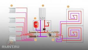
Typical diagram of a combined heating system with connection of radiators and underfloor heating circuits. This is the most technologically advanced and easily customizable option, but it also requires significant initial investment. 1 - heating boiler; 2 — safety group, circulation pump, expansion tank; 3 - manifold for separate two-pipe connection of radiators in a star configuration; 4 — heating radiators; 5 - underfloor heating manifold, includes: bypass, three-way valve, thermostatic head, circulation pump, combs for connecting underfloor heating circuits with gearboxes and flow meters; 6 - heated floor contours
There are quite a large number of variations in the design of the boiler room piping, and each individual case has its own principles of operation of the hydraulic system. However, if you do not take into account very specific options, then there are only five ways to coordinate the operation of heating devices of various types:
- Parallel connection of the underfloor heating collector to the main line of the heating unit. The insertion point into the main line must be made up to the connection point of the radiator network; the coolant supply is provided by an additional circulation pump.
- Association according to the type of primary and secondary rings. The line, wrapped in a ring, has several supply connections in the supply part; the coolant flow in the connected circuits decreases with distance from the heating source. Flow balancing is performed by selecting the pump supply and limiting the flow with regulators.
- Connection to the extreme point of a coplanar manifold. The movement of the coolant in the heated floor loops is ensured by a common pump located in the generator part, while the system is balanced according to the principle of priority flow.
- Connection through a hydraulic separator is optimal when there are a large number of heating devices, a significant difference in flow rates in the circuits and a significant length of underfloor heating loops. This option also uses a coplanar manifold, but the hydraulic arrow is necessary to eliminate the pressure drop that interferes with the correct operation of the circulation pumps.
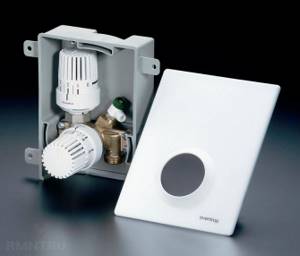
- Local parallel loop connection via unibox. This option is well suited for connecting a short-length heated floor loop, for example, if you need to heat the floor only in the bathroom.
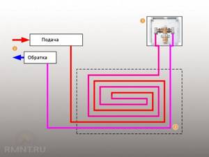
The simplest option is to connect a heated floor circuit to a radiator heating system with a coolant temperature of 70-80 °C. 1 - line with supply and return of the high-temperature circuit; 2 - heated floor contour; 3 - unibox.
It must be remembered that the nature of the operation of a heated floor may also change depending on the installation pattern of the coil. The “snail” scheme is considered optimal, in which the tubes are laid in pairs, which means that the entire area is heated almost evenly. If the warm floor is arranged as a “snake” or “labyrinth”, then the formation of colder and warmer zones is practically guaranteed. This drawback can be eliminated, including through proper configuration.
Cable floor. Connection
Heated floor kit
Heated floor kit
Equipment:
- heating cable or thermomat;
- thermostat. It can be mechanical or electronic. In the first case, the desired temperature is simply set using a rheostat. In the second, the device has a software device that sets the temperature using a relay;
- temperature sensor Supplied complete with thermostat.
Laying scheme
Installation work:
- First we prepare the place. We remove debris and level the surface of the base;
- lay insulation. It will not allow the heat to go down.
We lay a cable or thermomat on the insulation. The cable can be laid out in the form of contours or a coil;
- We fasten the cable to the insulation with mounting tape;
- install a temperature sensor. The wire for connecting it to the thermostat must remain free;
- connect the floor to the thermostat. The connection diagram is indicated on the device. Two separate terminals on it are for connecting a temperature sensor, the rest are for connecting the floor and the general network;
- We check the functioning of the floor. It is better to do this before pouring the screed. What if the cable was damaged during installation or was initially faulty;
- prepare the screed solution;
- fill the screed. If the floor covering is tiles, then the thermomat can be laid on top of the screed. It will fit well in tile adhesive;
- The screed will set within a day and you can work on it. We install the thermostat. We attach it to the wall. To provide the floor with electricity, it is better to make additional wiring independent of the general wiring. The fact is that heated floors consume a lot of electricity. There is a possibility that the general network may simply not withstand the additional load;
- laying the floor covering.
It should be taken into account that there are two types of thermomat. Single-cable and double-cable mat. Connection diagrams for both are given in the instructions accompanying the thermostat.
By the way, the thermomat can also be installed in the wall under the plaster.
cable heated floor
Control elements
Setting up a heated floor collector is impossible without special devices. With their help, the optimal heating mode of the system is established and water flows in the pipelines are regulated. Each of them performs a specific function.
- Water temperature sensor
Installed on the inlet and outlet pipes of the device. These devices do not affect the operation of the system, but indicate the current heating rate. The difference in values can be useful in calculating operating efficiency. They also serve as an indicator of heating mode violations.
- Central thermostat with servo mechanism and sensor.
It is mounted on the inlet pipe of the inlet manifold and connected to the return pipe with cooled coolant. The temperature sensor is placed in the comb body. There is a rotary knob on the body of the thermostat with which you can set the required temperature level. The device receives readings from the sensor about the degree of water heating. Depending on this, the flow of cold and hot coolant is regulated.
- Servo drives on the inlet comb nozzles
According to the principle of operation, they are completely similar to a thermostat, but with minor additions. With their help, the volume of water flow for each circuit of the water floor is regulated. Depending on the model, this can be done in manual or automatic modes. For the latter, servos with built-in temperature sensors are used, which can be connected to a common remote thermostat.
- Flow meters
Devices that are optional for installation, but which, however, can become effective elements for manually controlling the operation of a water heated floor. They are installed on the return manifold pipes and are locking mechanisms with a glass bulb.
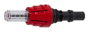
When you turn the head on the body, the rod in the device changes its position. This affects the volume of liquid passing through it. For clarity, a measurement scale is printed on the surface of the flowmeter, indicating the flow rate of water l/min.
Review of popular models
Servo drives for water heated floors are produced by different manufacturers. Each model has its own characteristics.
VALTEC
VALTEC is a manufacturer of devices for water and heating supply for the home. A group of Russian and Italian specialists is working together to create products. VALTEC produces the following drives to regulate the operation of a floor-type heating system:
- TE3042.A. Belongs to the group of normally open. Designed to control valves of climate systems using commands that will be set by a thermostat, controller or manual switch. Device power – 2 W, conductor cross-section – 0.75 sq. mm. The connecting size is M30x1.5;
- TE3061.0. This is a normally closed electrothermal device. Designed for three-way valves. The operation of the device is possible due to the thermal expansion of the liquid - toluene. Drive power – 2 W, conductor cross-section – 0.22 sq. mm;
- TE3041A.0. The device works thanks to the presence of liquid in the body, which expands under the influence of temperature. Belongs to the group of normally open. Connection to the valve occurs through an adapter, which is included in the kit. Unit power – 1.8 W, conductor cross-section – 0.75 sq. mm.
Watts
Watts is the world's leading manufacturer of heating equipment of various formats. It is distinguished by high quality, affordable price and efficiency. Servo drives from Watts are models with an electromagnetic motor. Popular series:
- 22C. It is installed on the return pipeline valve and regulates the flow of coolant into the underfloor heating system. Power is 2.5 W. Depending on the model, the 22C series includes normally open and closed devices. Protection class – IP44;
- 22СХ. They belong to electrothermal devices to ensure the efficient operation of water heated floors. There are normally closed and open models. The level of power consumption in normal operation is 1.8 W. The operating temperature of the liquid in the system is +110°C;
- 26LC. Electrothermal drives for the collector. There is an LED indicator on the case that indicates its operating mode. If the green light comes on, voltage is supplied to the drive, blue light means the device is open.
REHAU
Drives for adjusting the operation of water heated floors from a German manufacturer. They combine innovative developments and proven quality over the years. The most popular models from REHAU:
- UNI for 230, 24 V. The device is mounted on the valves of the manifold group using a special adapter. Applies to normally closed devices. Control over the operation of the drive is carried out through an indicator. Connecting cables with a cross section of 2x0.5 sq. mm;
- Drive 230, 24 V. When de-energized, the valve is in the closed state. To control the functioning of the device, a light indicator is placed on the case.
LUXOR
The Italian company LUXOR specializes in the production of water shut-off valves and systems for regulating the temperature of the heating system for the home. The installed collector group will include an SM 1347 drive. It is designed to regulate the temperature of the supplied coolant for a warm water floor. Main technical characteristics of the device:
- power supply – 24 V;
- The operation of the device is provided by a stepper motor. Its control is electronic;
- there is an LED indication on the case that indicates the operating mode;
- installation takes place in a straight position - vertical or horizontal;
- maximum temperature in the system – +100°C;
- cable 1.5 m long;
- device storage temperature – from 0 to +50°С;
- The body is made of synthetic materials. Its color is gray;
- Warranty available - 2 years.
How does the collector work?
Water floors are laid in various ways, for example, concrete or flooring, but regardless of the technology chosen, it is necessary to purchase and install a manifold cabinet.
In the future, two pipes will be inserted into it:
The cyclical nature of the process is ensured by another built-in component of the system - a circulation pump. One way or another, during the operation of a heated floor, say during repair work, the system has to be turned off. To do this, each of the pipes is equipped with shut-off valves. A plastic pipe and a metal shut-off valve are connected to each other through a compression fitting. Then a comb is connected to the valve, mounting an air vent on one end and a drain valve on the other. After assembling the cabinet, they proceed directly to installation. And only with a comb already installed on the wall can you cut the circuit pipes to length.
Collectors
- Water collectors
- Collector blocks
- Manifold fittings
- Manifold cabinets
- Quick assembly groups
- Mixing units
View:
On the page:
20 25 50 75 100
Sorting:
from cheap to expensive from expensive to cheap
VALTEC VT.4410.NE manifold fitting for plastic pipe.
VALTEC VT.4410.NE manifold fittings for connecting a plastic pipe are nickel-plated brass connectors of the CW 617N series with union nuts and ferrules made of EPDM rubber. The manifold fitting VT.4410.NE is used for connecting pipes made of plastic, cross-linked polyethylene...
Price: 79.98 UAH.
VALTEC VT.4420.NE manifold fitting for metal-polymer pipe.
Fittings with a ferrule ring and a union nut VALTEC VT.4420.NE are used to connect metal-polymer pipelines to manifold blocks, manifolds, radiator units and valves that have a threaded external connection of the Euroconus standard. The main advantage of brass fitting...
Price: 83.59 UAH.
VALTEC VTc.709.N manifold fitting for polyethylene pipe
The compression fitting for PEX pipes VTc.709 is a brass manifold connector for connecting polyethylene pipes to manifold blocks, manifolds of the VTc.500, 560, 580 brands, which have a ½ external thread and a “cone” type of connection. The manifold fitting VTc.709 can be used in engineering...
Price: 80.24 UAH.
VALTEC VTc.710.N crimp manifold fitting for metal-polymer pipe.
Brass manifold connector with ferrule ring and union nut VALTEC series VTc.710.N is a fitting that provides connection of metal-plastic or metal-polymer pipes to the outlets of a distribution manifold with a diameter of ½ and a “cone” connection type. Installation of collector...
Price: 89.01 UAH.
Press fitting with union nut VALTEC VTc.712.N.
The press fitting with a union nut VALTEC VTc.712.N is used to connect metal-plastic pipes with dimensions of 16 x 2 mm to the VALTEC manifold systems of the VTc.500, VTc.560 VTc.580 series or to the VALTEC manifold tee of the VTp.734 series. In a press fitting with a union nut VTc.712.N pr..
Price: 94.69 UAH.
Press fitting with union nut for Eurocone VALTEC VTc.712.NE.
Nickel-plated brass press fitting VALTEC VTc.712.NE is a high-quality connector with a transition to a threaded connection using a union nut. Press connector VTc.712.NE is used for connecting metal-polymer pipes and metal-plastic pipes to manifold systems..
Price: 95.46 UAH.
Manifold block VALTEC Vtc.594.EMNX
The VALTEC manifold block of the Vtc.594.EMNX series is a manifold unit for floor (warm floor) and radiator water heating systems with manual and adjustable shut-off valves, and it is possible to adjust and install an electrothermal servo drive. VALTEC Vtc.594.EMNX is equipped with an autonomous...
Price: 2,688.88 UAH.
Manifold block with built-in flow meters VALTEC Vtc.596.EMNX
The VALTEC Vtc.596.EMNX collector unit with built-in flow meters is used for uniform transportation of coolant in water-type heating systems, such as: convectors, radiators, heated floors for heating open-air areas (stadiums, sports fields). Maximum permissible..
Price: 3,928.57 UAH.
Water manifold with external thread VALTEC Vtc.500.N
VALTEC Vtc.500.N is a nickel-plated brass water manifold with 2-4 outlets of 1/2 diametrical dimensions and an external threaded connection. The distance between the outlets of the VALTEC Vtc.500.N water collector is 40 millimeters. The diametral parameters of the Vtc.500.N collector itself are ¾”, or..
Price: 193.50 UAH.
Water manifold for “Eurocone” with external thread VALTEC Vtc.500.NE
Vtc.500.NE is a nickel-plated brass water manifold with an external threaded connection according to the Eurocone standard. The water manifold for “Eurocone” with external thread VALTEC Vtc.500.NE is available in models with 2-4 outlets with diametrical data of 3/4″. The Vtc.500.Ne collector allows...
Price: 313.47 UAH.
Water manifold with internal thread VALTEC Vtc.550.N
Nickel-plated brass manifold VALTEC Vtc.550.N is a water manifold with internal thread, which is available in three variations - from 2 to 4 outlets with diametrical dimensions of ½”. The VALTEC Vtc.550.N water manifold model is represented by manifolds with a diameter of 3/4 and 1″, and threaded pipes..
Price: 192.98 UAH.
Water manifold with shut-off valves VALTEC Vtc.580.N
Water manifold with shut-off valves VALTEC Vtc.580.N is a nickel-plated brass manifold, which is connected to the outlet pipes using metric threads. The connections of the Vtc.580.N water collector housing with the outlet pipes are sealed with anaerobic glue, which is not harmful to...
Price: 562.44 UAH.
Pumping and mixing unit for heated floors VALTEC COMBI VT.COMBI.0.180
The VALTEC COMBI pump and mixing unit of the VT.COMBI.0.180 series is used for water-type heated floors, where the coolant, whose temperature is 20-60 60 ° C, is prepared by mixing water from the return line. The adjustment is carried out by a valve with two strokes, which is located in the supply manifold and...
Price: 9,030.00 UAH.
No matter how complex and expensive the current heating system is, it will still be necessary to ensure control over the uniform heating of all radiators located in the house.
The collector is considered a mechanism that regulates the supply of coolant and equalizes the temperature regime in all pipe loops.
Such a mechanism can be easily installed both in the heating system and directly in the heated floor.
Features of heating collectors
Heating collectors can be called distribution devices that connect each of the flows in the underfloor heating system, cold and hot water supply into one. Often, the product in appearance resembles a mixing unit, equipped with elements such as flow meters, servo drives, air vents, brackets, drainage channels, and so on.
Depending on how many heating elements are present, there are collectors having both two and twelve connections.
Among other things, combs can vary in size and the ability to cut off or regulate water flows.
Thanks to the distribution elements, it will be possible to control the temperature of all heat exchangers or the room as a whole, so you can count on significant savings in resources.
The manifold for heated floors has other advantages. For example, if one of the components breaks down, it can be turned off without stopping heating the house.
If the client has no idea which floor heating collector should be chosen, it is better for him to contact competent managers who will advise him and provide comprehensive information about operating conditions.
Heating collectors have a fairly simple design system. One of the parts of the collector controls the inlet pressure of the coolant, while the other controls its return. The number of collector outputs must be calculated taking into account the actual number of circuits. Depending on the configuration, the heating manifold can solve different problems. This is about:
- complete elimination of fragmentation of heating - the floor area will warm up evenly;
- eliminating hydraulic imbalance;
- balanced temperature control in all available circuits;
- control over temperature and coolant flow;
- absolute coherence of the operation of each component of the underfloor heating/heating system;
- the possibility of eliminating emergency situations, in the event of which it will be enough to turn off the tap.
Specifics of choosing collectors
As mentioned earlier, the heating manifold is really difficult to install. But it is much more difficult to choose the right equipment. There are several parameters to consider before purchasing. One of them is the maximum permissible pressure for the model.
With its help, the type of material from which the product is made is determined. You also need to pay attention to the throughput of the unit, the presence of auxiliary devices and the number of inlet pipes (it is important that it corresponds to the number of cooling circuits).
Ukraine collectors can be called truly high-quality if they have the ability to attach additional elements. Each operational parameter must be indicated in the product passport.
Buy collectors on favorable terms
The Valtec online store offers manifolds of various types to facilitate interaction with heating and heated floors. The assembled products will require a minimum of time during the search for the necessary components and during installation. The build quality is considered ideal, as hundreds of users have been able to verify.
If you carefully read the catalog, it will become clear that they offer reliable collectors at an affordable cost. All products are manufactured at Valtec factories, so there are no extra charges for the services of intermediaries. Delivery to Ukrainian settlements is possible - the client will receive the products as quickly as possible. Good luck!
Source: https://www.valtec-kiev.com.ua/kollektory/
How to save money on a mixing unit
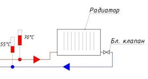
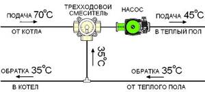
Many master plumbers consider it an integral part of the underfloor heating manifold, although these are 2 different elements that perform separate functions. The task of the comb is to distribute the coolant along the circuits, and the mixing unit is to limit its temperature to 35-45 °C, maximum 55 °C. The collector connection diagram shown below works according to the following algorithm:
- While the system is warming up, the two-way valve on the supply side is completely open and allows maximum water through.
- When the temperature rises to the calculated value (usually 45 °C), the remote sensor acts on the thermal head, and it begins to block the flow through the valve, pressing on the rod.
- After the valve mechanism is completely closed, the coolant, stimulated to move by the pump, circulates only in a closed floor heating network.
- The gradual cooling of the water is detected by a temperature sensor, causing the thermal head to release the rod, the valve opens and a portion of hot water enters the system, while some of the cold water goes back. The heating cycle repeats.
Good news for those who are very limited in funds, but want to heat themselves with warm floors: installing a two- or three-way valve with a pump is not always necessary. There are two ways to reduce the cost of the system by avoiding the purchase of a mixer:
- power the heating circuits directly from the gas boiler through the manifold;
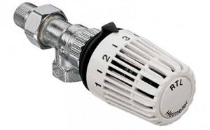
- install RTL thermal heads on the manifold valves.
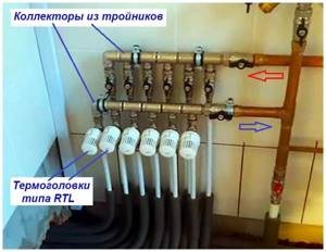
The manifold assembly, assembled from brass tees, provides for regulation by automatically limiting the reverse flow with RTL heads.
Let us immediately note that the first option contradicts all the canons and cannot be considered correct, although it is used quite successfully. The bottom line is this: high-tech wall-mounted gas boilers can maintain the temperature of the supplied water at 40-50 °C, which is acceptable for heated floors. But there are 3 negative points:
- In spring and autumn, when there is minimal frost outside, the boiler will not be able to lower the coolant temperature below 35 ° C, causing the rooms to become stuffy and hot due to heating of the entire floor surface.
- In the minimum combustion mode, the parts of the heating unit are covered with soot twice as quickly.
- Due to the same mode, the efficiency of the heat generator is reduced by 5-10%.
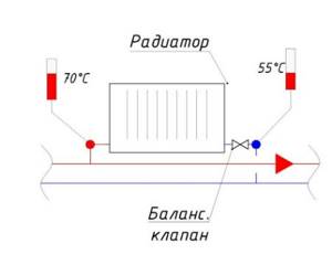
Thermostatic heads of the RTL type operate on the principle of a two-way valve, only they are located on each circuit and are not equipped with remote sensors. A thermoelement that responds to changes in water temperature is located inside the head and blocks the flow along the circuit when it has heated up above 45-55 ° C (depending on the adjustment). In this case, the comb is connected directly to a heat source running on any type of fuel - wood, diesel or pellets.
Important condition. For normal operation of heated floors controlled by RTL thermal heads, the length of each circuit should not exceed 60 m
More details about the design of such heating and the correct schemes for assembling the collector are described in a separate instruction and in the next video:
Collector diagram
The cabinet must be located in a room whose space provides free access for supply and return pipes. The side outlets of the manifold are connected to the ends of these elements to supply and receive heating fluid. Before performing the last step, it would be useful to install protective shut-off valves and temperature regulators in the system.
Valves, pipe ends and the manifold are connected using compression adapters - fittings that have completely different inlet and outlet sizes depending on consumer preferences. Often, the outlet pipes of a heated floor are connected to the collector using connectors that include a support sleeve, a ring with a clamp and a brass nut. The simplest connection consists of simple clamps with locking valves. The supply and return pipes are connected to the manifold, and it, in turn, is attached to the floor coolant outlets.
The named scheme is the simplest and will not be able to fully ensure proper control over the entire heating system, since it completely depends on the type of boiler (the only thing is that the shut-off valve can be closed a little to slightly reduce the supply of heating mass).
Connection methods
You will need the following materials and devices:
- Pipeline;
- Pipeline components;
- Boiler;
- Three-way thermostatic valve;
- Pump assembly.
Some people try to use the simplest installation method - to embed the underfloor heating system directly into the central heating system. However, this approach threatens serious damage to the pipeline, because The temperature for radiators is much higher than that needed for the floor. Also, if such a “homemade device” is discovered by supervisory authorities, the owner of the apartment faces serious penalties and an order to completely dismantle the warm water floor.
Options for laying a pipeline without a collector: snail and snake. Moreover, both schemes must consist of a double pipeline: 2 parallel loops to the heated floor - supply and return.
- The advantage of the “snake” is that you can distribute heating zones. For example, go around furniture or plumbing fixtures.
- The advantage of the “snail” is more uniform heating of the entire area.
After laying the pipeline, it must be connected to the boiler. You must first calculate the pump power. The following formula is used:
G =Q X 0.86/Δt,
where G is the system capacity (l/h),
Q - system power (W),
0.86 — conversion factor in Kcal/h,
Δt—flow-return temperature difference (°C).
A pump is needed to ensure the speed of coolant movement through the pipes. Depending on the type of pump, it can be controlled either manually or automatically. The device is mounted on the supply pipeline. In a system without a mixing unit, the pump device is located under the boiler. The circuit between the pipeline with the pump and the boiler is closed by a three-way thermostatic valve.
In order for the heated floor to work stably without installing a mixing unit, you should choose a high-quality, powerful boiler. Electric or gas – it doesn’t really matter. The main thing is that the power of the device is designed specifically for the designed heated floor. Experts recommend choosing models with a pump.
Connection principle
When installing underfloor heating in an apartment, you need to be able to correctly connect the collector to the system. After all, the circuits are connected to the boiler not directly, but through collectors, pumps and sensors.
- A plug is provided for the outlet of the distribution manifold. In some cases, a branching network, a drain tap and a device for removing air from the heated floor pipes are installed in this place.
- This design is made on the supply heating branch and on the return one. For heated floors, it is recommended to install not one, but a pair of similar combs and, accordingly, related devices.
- The manifold mixing unit is placed in a special cabinet so that unwanted persons do not have access there, and maintenance and parameter changes are carried out by one person. The cabinet is locked and can be made in external or internal versions.
- You need to make a collector yourself, taking into account the number of connected heating circuits and the material for making the device. If there are two branches of underfloor heating with different required temperature conditions, the collector is connected to supply water of different heating levels to these branches. If a large length of pipes is envisaged, an additional pump is built into the system to create the required pressure.
- Each pipe outlet from the manifold for underfloor heating must be equipped with a ball valve. With its help, it will be possible to turn off a number of heating devices without stopping the entire system.
- Supply and return manifolds must be located on each floor of the main riser. From them, pipes go into the floor or stretch along the walls to heating radiators. In the case of floor heating, when the pipes are embedded in a screed, a device must be installed to trap and bleed air from the system.
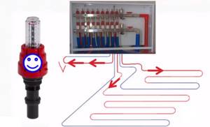
Functionality and principle of operation of the flow meter
The main function of flow meters or, as they are also called, float rotameters in a heated floor system is to regulate the coolant flow in water circuits. Installing such a device allows you to:
- avoid excessive consumption of electrical energy in the process of heating the coolant;
- ensure uniform heating of all water circuits;
- eliminate temperature fluctuations in different rooms.
The need to use flow meters arises in buildings where floor coverings of different areas are heated. Large rooms require a longer pipeline length, so they heat up less intensely than small rooms. Therefore, it is possible to achieve uniform heating and ensure a comfortable temperature throughout the entire house only with such a device.
The flow meter for a floor heating system is a mechanical type device with a plastic or brass housing. Inside it is a float made of polypropylene. On the top of the body there is a transparent bulb with markings. During the circulation of the coolant, the float comes into action, moving up and down. According to its location, you can use a scale to determine the volume of liquid in the pipeline.
Classification
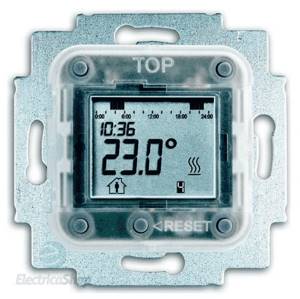
Depending on the design features, the thermostat can be:
mechanical, in such a device the temperature level is set manually. Note that this type of device is more reliable in operation;
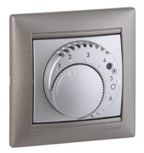
Legrand thermostat with mechanical timer
electronic (digital), this type of device has great functionality. In particular, the device display shows the current status of the device, including the temperature of the heating elements. A significant disadvantage of electronic devices is the cost; they are much more expensive than their mechanical counterparts.
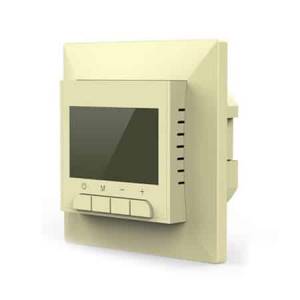
Photo of the Priotherm digital device
Electronic controllers also include a touch-sensitive and programmable temperature controller. Programming modes allows you to set an operating algorithm for a specific time of day or days of the week, which significantly reduces energy consumption.
As an example, we can cite products from brands such as Devireg, Din, I-warm, Eberle, Gira, RTC, etc. Many manufacturers produce models equipped with a remote control that allows you to control the device via infrared radiation (Energy, Roomstat, Oventrop, Unica, Rehau, etc.).
Microlin programmable device
A two-zone (two-channel) temperature controller allows you to set the necessary floor heating parameters for two different rooms. Accordingly, two independent switching relays, triggered by two temperature sensors, are used for control.
This implementation scheme allows you to control the temperature in each room from one device (Jung, Ensto, Menred, Merten, Valena).
Depending on the installation method, devices are usually divided into overhead and built-in. The first are mounted directly on the wall, for the second you need to make a hole, similar to the one for built-in sockets.
Built-in Nexans device with trim panel removed
Photo: prepared place for installing a built-in device
Optimal temperature parameters
Setting up a water heated floor is carried out depending on individual needs. Some people like it when the room is warm, while others prefer invigorating freshness, even in the most severe frosts. But despite this, there are general standards that were developed taking into account sanitary standards, these include:
- floor heating up to 28 degrees;
- if there is another heat source or if you live indoors permanently, the ideal level is from 22 to 26 - these are optimal conditions for a person;
- if this type of heat source is the only one, or it is located in the bathroom, corridor, balcony, or in a house where people do not live permanently, it is permissible to raise the degree to 32.
Therefore, when regulating water floors, in addition to your preferences, so that the microclimate in the apartment is healthy, you should take these standards into account.
How to choose
First of all, you need to decide on the type of device. Mechanical devices are easy to operate, inexpensive, but have poor functionality. As a rule, they are installed in small rooms, for example, in a bathroom or glazed balcony.
Video: choosing a thermostat for a heated floor.
Electronic devices are preferable because they allow you to control the operation of the heated floor over a wider range. Depending on the power of the heating cable (film heating element), the appropriate thermostat is selected.
Separately, we note that a programmable controller is more suitable for large office spaces than for an ordinary apartment. In this case, you can set different operating modes for the period when there are people in the room or not. Agree, there is no point in heating an empty room to a comfortable temperature.
When choosing a regulator, you should pay attention to the manufacturer; products manufactured by well-known brands are famous for their high quality and reliability, in contrast to devices from unknown Chinese companies. Considering that electronic temperature controllers are quite complex devices, make sure that in your city there is a certified service center that services the products of this manufacturer. Otherwise, when malfunctions occur, repairing a failed device may become problematic.
Considering that electronic temperature controllers are quite complex devices, make sure that in your city there is a certified service center that services the products of this manufacturer. Otherwise, when malfunctions occur, repairing a failed device may become problematic.
Is a mixing unit necessary?
A legitimate question, especially considering the decent cost of the collector. It should be recognized that water heated floors without a mixing unit can work normally, but only if they have one heating circuit. What does this mean in practice?
According to the manufacturer’s recommendations, the length of the pipe to be laid in heated floors should not exceed 70 m. Considering that with a maximum gap in the pitch between the pipes, this amount will only be enough for 7 m², it is not difficult to calculate; to heat a medium-sized room, three circuits will need to be laid at once.
In most cases, heated floors are installed for several rooms at once: hallway, bathroom, kitchen, etc. It is unrealistic to ensure a uniform supply of coolant without connecting to the boiler room manifold. But if you need to heat only one small room, then you can do without a mixing unit.
Installation without a collector has several disadvantages, including: the supply of coolant with a temperature identical to that in the general heating system, the impossibility of automatically removing air pockets and controlling pressure.
This is interesting: Which floors are better to make in a private house - we outline it point by point
Stages of manufacturing a distribution comb
Drawing up a heating project
When drawing up a diagram of the passage of branches and connections to the collector, many issues should be taken into account.
- How many heating branches will be suitable for the heating boiler?
- What type of heating boiler and its operating characteristics. Sometimes there are two or more heating devices.
- The number and description of the characteristics of heating devices that will be connected to the system in subsequent years (solar panels or fuel pumps, etc.).
- Description of the operation of all additional equipment, storage water tanks, feed valves, pressure gauges and thermometers, sensors and safety groups for them.
- It is necessary to determine the parameters for connecting each of the devices to the system, direct and reverse supply of warm water.
- A diagram of the entry of the pipe of each circuit into the collector is drawn up. Pipes of solid fuel boilers and additional heating boilers are usually located on the sides of the collector. If a gas or electric boiler is connected without using a hydraulic arrow, then it is also cut in from the side. If not, then it is more convenient to enter from above.
- The inlet of the heating circuit pipes is located at the top and bottom of the comb. The distance between the entrances can be made in arbitrary sizes, but it is recommended to make them 10–20 cm. To visually highlight each circuit, it is recommended to keep the gap between the direct and return entrances and keep the heating boiler the same.
- For all devices included in the system, such as pumps, modules, etc., the distance between the return flow and the outlet is indicated in the technical parameters and must be strictly maintained.
Manufacturing process
It is most convenient to make a distribution manifold from a square pipe.
First, we prepare two sections of pipe according to the given dimensions, cut the sections to create outlet pipes from molded products of round cross-section. Be sure to clean all parts from rust; it is advisable to treat them with an anti-corrosion compound.
On the body of the pipe, mark the holes for future entrances and exits, checking the diagram drawn up earlier. After checking the data, drill all holes. Next, you need to start assembling the manifold, secure all the connections between the pipes and the manifold by welding, carefully scalding all threads and pipes. After welding the selected type of fastener, knock off the scale and clean the welding areas. All that remains is to paint the collector with oil compounds to protect it from corrosion and give it a finished look.
How to adjust a warm water floor manually preparation and input
Manual adjustment is carried out using a conventional tap called a thermal head. It is mounted on the return and supply. Using a crane allows you to avoid loading the system with automation and additional equipment. This significantly reduces costs, but creates a number of inconveniences. High-quality and quick adjustment of a warm water floor with a thermal head is a myth. You will have to turn the tap often, and when determining the temperature, rely solely on personal sensations.
Important! It is considered more convenient to regulate water heated floors using rotameters (flow meters), which are installed at the entrance to each circuit (manifold installation location). All you need is to control the permissible difference in instrument readings. It is 0.3-0.5 l
It is 0.3-0.5 l.
Correct adjustment of a heated floor with a thermal head requires compliance with the commissioning standards of the entire system. Otherwise, the system of main or auxiliary heating of air masses from below the room will malfunction.
Equipment and capabilities
Products are manufactured under the Valtec brand by an Italian company. They have been on the Russian market since 2003, so they know our realities first-hand. We produce a wide range of plumbing engineering fixtures and devices. And collectors for heated floors are among them.
general description
The Valtec underfloor heating manifold is made of brass or stainless steel. Or rather, most often, the body is made of stainless steel, and the “filling” is made of brass. In the catalog they are called a manifold block, since there are a couple of devices - for the supply and for the return pipeline. Complete kits are equipped with:
- there are flow meters on the feed comb;
- on the return pipeline there are manual shut-off valves.
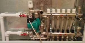
Below is the supply and there are flow meters. At the top is the return pipeline, manual valves are installed
In this option, using flow meters, you can adjust the coolant flow in each of the loops, and manual valves on the return pipeline serve to block circulation. But this configuration can be automated. To do this, servo drives are installed on manual valves, which are connected to thermostats installed in the premises. In this way, a constant floor or air temperature can be maintained. Depends on where the heat sensors are installed, because the thermostat reacts to their readings.
An automatic air bleeder is also installed on the Valtec manifold. This is a device that allows you to remove air trapped in the coolant automatically.
Range
All collector blocks for Valtek underfloor heating can be divided into two groups: with and without adjusting flow meters. There are only three options in the first group and two in the second, but in each the number of connected taps is from two to twelve.
- With flow meters on supply
- VTc.594.EMNX. Body - stainless steel AISI 304, fittings - brass CW617N, seals - EPDM 70Sh, number of outlets - from 2 to 12. Operating pressure 8 bar, nominal diameter of manifolds - 1 inch, outlets - 3/4″ external thread, connection - eurocone. Price - from 9 thousand rubles. (for 2 outputs), up to 25 thousand (for 12 outputs).
- VTc.589.EMNX. Manifold for propylene glycol systems. Body - AISI 304 stainless steel, brass fittings and EPDM 70Sh rubber seals. Working pressure 9 Bar, coolant temperature not higher than 90°C. The nominal diameter of the collectors is one inch, the outlets are 3/4 inch with a Eurocone.
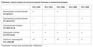
Compatibility table for various Valtec manifolds with components
- VTc.596.EMNX. Valtec brass manifold (CW617N brass) with nickel plated. EPDM 70Sh seals, fittings made of the same brass. Working pressure 10 Bar, outlet connection - Eurocone, diameter 3/4″.
- nominal collector diameter 1 inch, number of outlets from 3 to 12. Price from 12 thousand rubles. for 3 exits, up to 38 thousand rubles. for 12 exits;
- nominal collector diameter 1 and 1/4 inches, number of outlets from 4 to 12. Price from 9 thousand rubles. for 4 exits, up to 45 thousand rubles. for 12 exits.
- With manual valves
- VTc.588.EMNX. Stainless steel underfloor heating manifold VTc.588.EMNX with thermostatic valves. Coolant - water or propylene glycol, operating pressure 9 Bar, temperature 90°C. There are manual adjustment valves on the supply side. The number of outputs is from 3 (6 thousand rubles) to 10 (15 thousand rubles), connection via a 3/4″ eurocone, nominal collector cross-section is 1″.
- VTc.594.EMNX. Valtec brass manifold for systems with elevated temperatures - up to 120°C, pressure 10 Bar. Includes manual balancing valves and thermostatic ones.
- nominal diameter of the collectors is 1″, the number of outlets is from 3 (10 thousand rubles) to 12 (27 thousand rubles);
- collectors with a cross section of 1 and 1/4″, the number of outlets from 4 (16 thousand rubles) to 12 (36 thousand rubles).
Design and principle of operation of servomotors
The main working element of the servo drive is the bellows. Those. same detail as in . A small, sealed cylinder with an elastic body is filled with a substance that is sensitive to temperature. Depending on whether the temperature increases or decreases, the volume of the substance changes accordingly. The figure - diagram clearly demonstrates the structure of the servomotor, where the bellows occupies the main place.
The bellows is in close contact with the electric heating element. Receiving a signal from the thermostat, the heating element is switched on from the mains and starts working. Inside the bellows, the substance is heated and increases in volume. Thus, the cylinder, which has increased in size, begins to put pressure on the rod, changing its position and blocking the path of coolant flow. Evaluating the operation of the servo drive, we can conclude that the device is not equipped with any motors, it does not have any gears or transmission links. The usual working connection is “thermal energy and electricity”. Hence the common name for the devices, thermoelectric regulators.
In order for the valve to become open again, the entire process is repeated only in the opposite direction. Lack of power causes the heating element to stop working. Consequently, the substance inside the cylinder cools, decreasing in volume. The pressure on the rod decreases, it rises, acting on the valve, and, consequently, hot water access to the system opens.
Having become familiar with the principle of operation of the device, it is important to remember that the mechanical action of the valve requires a certain time. Despite the fact that when a signal is received from the thermostat, the heating element begins to heat the substance inside the cylinder. The time required for changes in the physical state of the liquid is 2-3 minutes, so the valve is not activated immediately
Unlike heating, cooling of a liquid occurs more slowly. To the reverse process, i.e. Closing the valve will no longer take 2-3 minutes, but 10-15 minutes. If overheated, each servomotor should automatically turn off. For this purpose, the design provides an emergency shutdown mechanism.
For example: the servos used in the operation of the collector group are not all equipped with cylinders and cylinders with a substance. There are models in which this role is played by thermocouples, resembling a spring or plate, which heat up under the influence of the same heating element. Expanding, these parts again act on the rod, ultimately bringing the valve into working condition. You can determine what position the valve is in by changing the appearance of the servomotor. The retractable element signals the operation of the device. If this does not happen, it means that your device is not connected correctly or the heating system is not working properly.
Valtec manifold for heated floors: how to install Valtec
To regulate the flow of coolant in the floor water line and to control the temperature regime of the heating system, collector groups are connected.
The Italian company offers distribution blocks for the supply and return circuits with built-in flow meters and thermal heads. All connecting units are made without additional hermetic devices. The block diagram provides an automatic system for removing air from the main and draining the coolant. What is the difference between underfloor heating equipment? How to assemble a comb?
Description of the elements of the collector group
produces heating equipment for heating systems, radiator and floor. For water heating, a pipe and perforated insulation with fastening elements for the liquid line are purchased.
The pipes are connected to a comb, which consists of supply and return manifolds. What does a Valtec fluid distribution block provide?
- Supply manifold; a line with hot coolant is connected to it.
- The unit is equipped with flow meters that monitor the filling of the floor water circuit.
- An end tube with a float device is used to remove air.
- On the return circuit there are outputs for installing a thermal head. If the head is faulty, it is removed for repair. At the same time, the “warm floor” heating system operates in normal mode, without draining the coolant. The thermal head can be replaced with a servo drive or other control device.
- Flow meter valves; they are not permanently mounted on the hot water bar. A threaded connection is provided for them. If necessary, they can be removed.
- The system is equipped with a float device for air removal. A shut-off valve is connected to it, which allows you to remove the float if necessary.
- A drain valve is designed to remove coolant from the heating system. It has a hinged design.
- To ensure that the installation of the collector block for underfloor heating “Valtec” does not cause difficulties, the equipment kit includes adapter nipples and fittings. They are equipped with heat-resistant rubber gaskets.
- The operating temperature of the comb is 90 0C.
- Optimal pressure 8 bar.
- The filling level of the main line is 2.5 m3/h.
We recommend: How to install Eastec heated flooring?
Systems that do not include flow meters are cheaper, but if, along with large rooms, the mains of a bathroom or bathroom that are small in size are connected to the comb, then a device for filling the water circuit is necessary.
Along with a thermal head or servos, it regulates the filling of the water circuit and the room temperature. The flow meter is a valve. It closes, preventing hot water from entering a certain circuit. The device is triggered if the coolant flow exceeds the permissible limit.
The Valtek manifold for heated floors is made of stainless steel or nickel-plated brass. Fittings are made from hot-stamped brass. The air vent float is made of polypropylene.
- The size of the collector group depends on the number of outputs. If the block provides 3 outputs, then the length of the tube is 230 mm. With 7 outlets, the comb has a length of 430 mm.
- The pitch between the outlets is 60 mm.
- Outlet size 1”.
The comb is mounted on the wall using brackets. They have a figured design. The edge that fits tightly to the wall surface is provided for the cold circuit. A tube with hot coolant is fixed on the protruding surface.
Flow meters are located on the supply manifold. The equipment is configured when the circulation pump is turned on. Set the filling level of the highway to 2.5. The temperature parameters on the thermal head should be set before putting the heating system into operation.
How to assemble a collector?
The Valtec distribution block is manufactured assembled. Flow meters are already installed on the hot tube. There are thermal heads on the cold line, but the product may only have outputs for attaching temperature control devices. They are protected by plastic caps. The manufacturer gives you the opportunity to choose which automation to install: thermal head, servo drive.
Some small elements need to be connected to the collector group:
- On the right, shut-off valves are connected to the tubes. There are 2 of them in the set.
- A float device is connected to the valves to remove air.
- Opposite the air vents, drain valves are connected to the underside of the tubes.
- The ends of the comb are closed with plugs.
We recommend: How to connect a mixing valve for underfloor heating?
A circulation pump and a three-way or two-way valve are separately connected to the comb. These devices must be purchased separately. They are connected on the left to the tube into which the cold coolant flows. Use brass threaded fittings.
The cold and hot circuits are removed from metal pipes that are connected to the boiler or furnace. They are connected via a bypass at the outlet of the collector group. A circulation pump with a temperature sensor is installed between the circuits.
The rotameter is adjusted when testing the heating system. The protective sleeve must be removed from the device. Using the red ring, the upper bushing, set the rotameter to zero.
Next, using the same bushing, install the valve on the o for large rooms, on the o for small rooms. To fix the rotameter parameters, turn the lower ring to the right until it stops.
Return the protective cap to its original place. The rotameter may not have a locking ring. In this case, the pipeline fill indicator is set without fixing. Valve operation must be checked regularly.
Valtek collectors for heated floors are installed with a liquid heating system. The coolant can be water, antifreeze, glycol fillers that do not freeze at low temperatures. If the heating system is not used, then the coolant does not need to be drained.
The number of circuits on the distribution block is 3-12 pcs. If necessary, additional equipment can be connected to them to increase the flow capacity of the coolant to all rooms in the house.
The comb is mounted on the wall or placed in a manifold cabinet. The manufacturer provides a 10-year warranty on the equipment. Service centers are located in St. Petersburg and Moscow. The block will last more than 50 years.
If necessary, the rotameter or thermal head can be replaced without turning off the heating system. When using a programmable thermostat, the operation of the heated floor control unit can be carried out through electronic gadgets.
We recommend: How to connect an electric boiler for underfloor heating?
responded with an error: Daily Limit Exceeded. The quota will be reset at midnight Pacific Time (PT). You may monitor your quota usage and adjust limits in the API Console: https://console.developers.google.com/apis/api/.googleapis.com/quotas?project=268921522881
Loading…
Source: https://otoplenieblog.ru/oborudovanie/teplyj-pol/kak-sobrat-kollektor-valtec-dlya-tyoplogo-pola.html
Features of adjustment
For each individual room, the rotameters are adjusted separately. Control is carried out according to the diagram of the installed circuits
In this case, the level of heating of the liquid and pressure is taken into account
It is recommended to carry out balancing according to the following instructions:
- The total amount of coolant passing through the collector in one minute is determined. Indicators are taken in liters. The resulting value is taken as 100 percent.
- The percentage flow rate of each individual water circuit is calculated. The result is converted to liters per minute.
- The flow meter regulates the amount of liquid supplied to the pipeline.
Using these steps, you can perform long-term adjustments to the water circuit. To indicate the actual parameters, it is necessary to observe the flow meter readings. According to observations, it is possible to accurately determine the flow rate of the circuits connected to the collector.
Manifold with flow meters for heated floors
The flow meter is adjusted depending on the installed model. After connecting the device to the manifold, preliminary settings should be made by setting the initial position, which allows access to liquid.
In rotameters without a built-in valve, an additional locking device is used to set the “open” position. In this case, balancing is performed during the operation of the system.
Combination devices for metering coolant flow can be pre-set using full turns of the built-in valve. Each turn allows you to reduce the clearance by a set value.
Adjustment of the flow meter of the floor heating system is carried out taking into account the control of the fluid speed in one minute - from 0.5 to 5 liters.
Before setting up the rotameter, you should check the condition of the installed circuit. Trial testing is necessary to exclude the presence of leaks in the circuit, which could cause distortion of the indicators in the device.
The flow meter is an important element in a multi-circuit underfloor heating system. The device allows for a uniform flow of liquid into all individual pipelines. In order for heating equipment to function as efficiently as possible, you must select the right rotameter, as well as install and configure it in accordance with technical requirements.
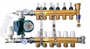
Finally, the heating system of my house is assembled. The boiler is started. Let me remind you that I decided to heat my house only with heated floors. Although there are not many rooms in the house, in order for the comfort in all rooms to be the same, it is necessary to adjust the heated floor. We will talk about how to set up a heated floor in this article.
Setting up a heated floor is not as complicated as it might seem at first glance. Generally speaking, setting up a heated floor consists of three stages. First, balancing the underfloor heating loops, then setting up the pump and mixing unit, and finally setting up the controller if you decide to automate the heating system. I decided to fully automate the heating system in my house. Therefore, I purchased a controller, servos and temperature sensors. Let's look at the first stage of setup in detail, since the success of the entire setup depends on how well it is done.
Where can combined heating systems be used?
Combined heating systems have technical features that limit their areas of use. What requirements must the premises meet?
Availability of water heating
This is the main installation condition. Underfloor heating systems can be connected in two ways.
- For existing heating boilers. The advantages of this solution are a reduction in the estimated cost of equipment and a reduction in installation time. Disadvantage - additional heating cannot function in autonomous mode. This causes an increase in thermal energy consumption, and the efficiency of using heated floors decreases.
- Install hotel boilers for floor heating. The disadvantage is a significant increase in cost. Advantages - complete autonomy, heated floors can be used for slight heating of rooms in the event of a short-term or slight drop in temperature outside.
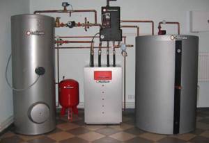
Heating boilers
Apartment buildings have their own individual requirements: the existing engineering heating system must allow the connection of floor heating; permission to install equipment is required from management organizations.
Compliance of electrical communications with new power indicators
The condition applies only to those cases when electric floors are used as additional heating of the room. The power per square meter of heating elements ranges from 150–200 W, taking into account the area of the premises, the total power reaches large values. Not all electrical wiring can withstand a significant increase in load; in addition, separate safety electrical fittings must be installed.

Electric heated floor
And one more problem. In some cases, connection will require permission from the owners of electrical networks. But they do not always issue it; they often refuse it under various pretexts: the technical capabilities of the transformer substation do not allow it, overhead and cable lines are not adapted, etc.
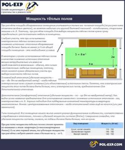
Heated floor power
Requirements for floor coverings
Despite the fact that manufacturers recommend installing floor heating systems on all types of finishing coatings, heating engineers and professional builders have a different opinion. What real limitations do experts put forward?
- Thermal conductivity indicators of the finishing coating. The higher the thermal conductivity, the faster the thermal energy is transferred from the coolants into the room, the lower the losses, the more effective the floor heating. Taking into account these basic data, it is recommended to install heated floors under ceramic tiles, artificial stone, and ordinary linoleum without insulation. Accordingly, it is not practical to install systems under wooden and insulated finishing floor coverings.
- Floor covering material. It is not recommended to heat floors made of block parquet, glued and natural boards. In addition to low thermal conductivity parameters, these materials react extremely negatively to high temperatures and fluctuations in humidity. Lumber inevitably drys out and cracks appear in them. Floor coverings have to be changed frequently, which means big financial losses.
One more word of caution. Heating systems must be in constant contact with cold air, heat exchange occurs due to convection and at the same time overheating of the equipment is avoided.
The best option is to provide for the possibility of a combined heating system at the building design stage. In the case of installing equipment in operating premises, it is better to get advice from specialists, find out about the necessary permits, and only then proceed with the installation of various systems and additional equipment.
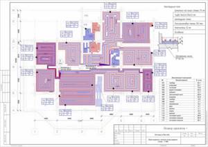
It is best to design a heating system at the stage of building a house
What is a heated floor collector?
The collector is a set of parts that allows you to control the coolant: mix and distribute liquid from parallel heating rings. The large cross-section and low speed make it possible to mix the hot coolant supplied from the boiler and the warm coolant leaving the heating pipes, which allows you to level the coolant temperature to the desired values.
In order to properly mix the return (cooled water from the circuits in the floor) and hot water to the desired temperature, various sensors are installed on the systems: a water temperature sensor, an outdoor heat sensor and a sensor that measures the pressure inside the system. Sensors provide information to valves that mix the coolant. The underfloor heating manifold, assembled with a pump and a special sensor, can control the pressure in the system.
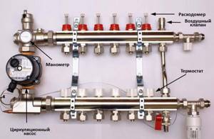
To better understand the principle of operation and the need for this system, pay attention to the following example: in a house, floor heating systems, heating radiators and a shower are connected to the boiler. A shower requires hot water at a temperature of approximately 70°C, heating radiators require a coolant with a temperature of 75°C, and floor heating requires only 50°C so that the temperature of the finished floor covering does not exceed the sanitary standard of 30°C.
What is a comb for heated floors: the role of the unit and the principle of operation
As a rule, the modern scheme of “warm floors” is quite complex, represented by several circuits with different lengths of pipes and the amount of coolant, so the role of such a unit as the comb should not be underestimated.
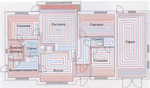
A properly adjusted comb allows you to control water consumption in individual areas of the “warm floor” system, therefore it is installed according to the needs for the thermal fluid
With two way valve
The main difference between the standard “comb” circuit, equipped with a two-way valve, is the continuous supply of water from the “return” without the use of special shut-off valves. In this case, the mixing unit for the “warm floors” system periodically mixes boiling water when the coolant cools below the specified parameters. This type of circuit has proven itself in practice, but only if the circuits are not excessively large.
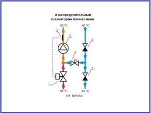
The device has a rather small range of temperature control
The diagram shows:
- 1 - two-way supply valve;
- 2 - circulation pumping equipment;
- 3 - temperature sensor;
- 4 — balancing type valve device;
- 5 - check valve.
The supply-type valve device is distinguished by the presence of a built-in liquid thermostat sensor that cuts off or adds a certain amount of hot thermal fluid if necessary. Stable temperature indicators around the perimeter make the operational life of the structure as high as possible. The advantages of this option are represented by smoothing out sharp jumps in conditions of low throughput of the valve device.
With three way valve
The category of universal equipment includes modern and highly efficient mixing units mounted in a “warm floor” system with a three-way valve device. This design assumes the mixing of boiling water with the “return” directly inside the housing, as well as the presence of a combined function of the supply valve device with bypass type balancing. The damper, which has an adjustable position, is built into the faucet.
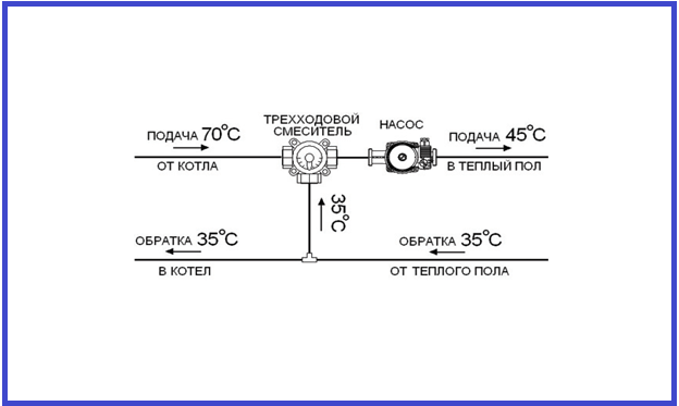
Installation of weather-compensating fittings allows for self-regulation of heating circuits in accordance with outdoor temperature indicators
This type of control valve is equipped with special weather-dependent controllers, thermostats and servos, therefore it is the best option for installation in multiple circuits for heating very large rooms.
The main disadvantage of the design with a three-way valve is the possibility of admitting hot coolant and the risk of excessive pressure inside the system, which negatively affects the pipes and significantly reduces their service life. At the same time, the difficulty of controlling temperature indicators as accurately as possible is due to the presence of increased throughput, so even a slight turn of the damper can cause a noticeable change in the temperature inside the “warm floor” system by 3–5˚C.
Installation algorithm
After the preliminary calculation of all components has been completed, the actual installation of the heated floor begins, which involves going through several stages.
Scheme of water floor heating
- Installation at a pre-selected location of the manifold cabinet. It contains a module consisting of a collector block and a pumping and mixing unit with ball valves, through which the connection to the high-temperature circuit will be made.
- Preparing the floor plane. If there are significant irregularities, measures are taken to eliminate them. The most effective option is a rough screed.
Connection diagram of the pumping and mixing unit to the heated floor
Installation and adjustment
According to the manufacturers' instructions, the rotameter is connected to the return collector, but there is an option to install the device on the supply.
The main requirement for installing the device is its vertical location. This installation allows you to determine the exact value of the liquid level in the flask. Therefore, the comb must be placed strictly horizontally in level.
The rotameter is connected by screwing into the corresponding socket on the manifold. The device comes with an O-ring and a union nut. There is no need to additionally seal the device with sealant or other materials.
The workflow of the connected circuit manifold - manifold and flow meter must be fully automated. Therefore, a temperature sensor is additionally connected to the system. With this scheme, when the specified temperature regime of the coolant is reached, the system blocks its full or partial access to the circuits.
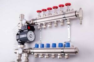
Installation of heated floor flow meters
The entire installation process and adjustment of the rotameter for heated floors is performed in the following sequence:
- The flow meter must be screwed into a specially designed technological hole on the manifold. The device is installed using a key in a strictly vertical position.
- Turn counterclockwise and remove the transparent bulb located at the top of the flowmeter housing. After this, you need to remove the ring that is installed for protection by the manufacturer. Then put the cap with the markings back on.
- Turn the body clockwise to the required pressure level. This action is a balancing of the coolant flow rate. In this case, the specified value should be displayed on the scale.
After such actions, it is necessary to check the operating process of the entire underfloor heating system. During operation of the heated floor, do not close the flask on the flow meter. The scale must be constantly visible, since sometimes there is a need for balancing during operation of heating equipment.
To protect it from external influences, it is recommended to place the collector group together with the flow meter in a special cabinet or make a niche in the wall with a closing door.
According to technical rules, identical installation of several contours, including their length, should be carried out. Otherwise, even using a collector with a rotameter will not give a positive result, and the system will not function correctly.
Calculation instructions
In order to correctly develop a project for laying a heated floor, you will need a preliminary calculation of the main indicators, focusing on their average values.
Do-it-yourself installation of water heated floors
Various factors have to be taken into account, including the role of the water floor as the main type of heating or its use as an additional heat source. Since detailed calculations for independent implementation are a complex process, in practice average parameters are used.
Valtec mixing unit connection diagram
- The rated power has limits of 90 - 150 W/m2. Higher values are selected for rooms with high humidity levels.
- When calculating the laying step, you need to focus on the range of 15–30 cm. The specific heating power is in inverse proportion to this indicator. That is, the larger the step, the less power.
Thermomechanical diagram of a pumping and mixing unit
Once the key parameters have been determined, a diagram can be developed in which the most efficient pipe laying is determined on an exact scale. After this, their total length is calculated. At the same time, it is thought through where the pumping and mixing unit and control elements will be located.