Correct selection
An interesting nuance: the name of this equipment does not depend on its design, but on the area of application.
When it comes to water supply, the tank is called a hydraulic accumulator. A container built into the heating with the same structural characteristics will be called a membrane or expansion tank. But it is important to take into account the information provided by the manufacturer. Each product has its own operating temperature and pressure:
- up to 4 atmospheres and up to 120 degrees Celsius - for heating;
- up to 12 atmospheres and up to 80 degrees – for water supply.
It is not the cheapest tank that is selected based on volume, but one that corresponds to the system parameters.
To normalize the pressure in the heating system, a number of devices are used. But the most important of them is the hydraulic accumulator. Its design makes it possible to automatically stabilize the coolant pressure when the temperature changes.
Purpose
The hydraulic accumulator is installed only for closed-type heating systems. They are characterized by high water pressure, which occurs due to its heating. Therefore, if the permissible value is exceeded, a compensation system is necessary. This is what the hydraulic accumulator is designed for.
It is a steel structure, which is internally divided into two chambers. One of them is designed to be filled with water from the heating system, and the second serves as an air compensator. To set the optimal pressure in the air chamber, a valve is provided in the accumulator. With its help, the degree of air injection is changed, thereby adapting the device to the parameters of a specific heating system.
The chambers are separated by an elastic membrane or rubber balloon. When the water temperature in the pipes rises above critical, a pressure surge occurs. The liquid, expanding, begins to press on the walls of the separation membrane. She, in turn, under the influence of this force, increases the filling volume of the water chamber. This leads to normalization of pressure within the entire system.
Connection rules, diagram
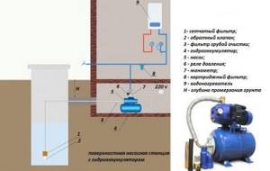
When installing a hydraulic accumulator, certain rules should be followed. First of all, you need to select an area in the heating main where it will be installed. Experts recommend installing the expansion tank in the return pipe with chilled water. But at the same time, it must be installed before the pumping equipment. The general installation diagram is as follows.
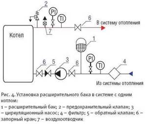
As you can see, a safety valve is installed at the outlet of the heating equipment to protect the line from differences in liquid pressure. It performs the same functions as a hydraulic accumulator, but is designed for higher pressure surges. An expansion tank is necessary to normalize heating operation at small pressure drops.
Before starting installation, please consider the following:
- Selecting an installation location. The main requirement for it is free access to the device. This is especially true for the air chamber control valve.
- There should be no other shut-off or control valves in the area between and the expansion tank. It can make significant changes in hydraulic resistance.
- The temperature in the room where the accumulator is installed should not be below 0°C.
- Its surface should not experience mechanical stress or external influences.
- The response of the pressure reducer to release air from the chambers must be set according to the parameters of the heating system.
Guided by these rules, you can install the expansion tank yourself. But at the same time, you should follow the connection rules, use products made of high-quality material and calculate the optimal tank volume.
To make the calculation, you need to know the total volume of the heating system, the optimal and maximum pressure in it, as well as the expansion coefficient of water. Formula for calculating the size of a membrane-type hydraulic accumulator:
- e – water expansion coefficient – 0.04318;
- C – total volume of the heating system;
- Pi – initial pressure;
- Pf – maximum pressure.
Let's consider an example of a calculation for heating with a total volume of 500 liters, an optimal pressure of 1.5 bar, and a maximum of 3 bar.
This technique will allow you to correctly select and connect an expansion tank for a closed heating system.
Expansion tanks, hydraulic accumulators, for heating and water supply systems
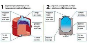
Closed expansion tanks and hydraulic accumulators have approximately the same design: a durable metal shell, divided inside by a rubber membrane into two sections.
One section contains water, the other contains air. As water pressure increases, the air is compressed, the size of the section with air decreases, and the membrane bends, water displaces the air. The device has a connection to the water supply system on one side, and a spool valve for pumping air on the other.
But devices are named not because of their design features, but according to their intended purpose.
Purpose
- Expansion tanks are designed to compensate for the expansion of water due to heating in heating circuits, as well as hot water supply (DHW).
- Hydraulic accumulators are designed to accumulate volumes of water under pressure in water supply systems that have a pressure pump, to reduce the frequency of switching on of this pump and to smooth out water hammer. An additional function is a supply of food-grade water up to 1/3 of the total tank volume.
The nuance is that the same device is used for both hot and cold water supply, but it can be called differently, depending on what it does in a particular circuit - it either accumulates (accumulates) a supply of water, or takes its excess during thermal expansion.
- The design feature of the hydraulic accumulator is often that inside there is not a membrane, but a bulb made of food-grade rubber, which is pumped with water. Water does not come into contact with the tank body.
- The expansion tank for the heating system is made of a membrane made of technical rubber, which divides the housing into two compartments, and the coolant (not always water) is in direct contact with the housing.
How to differentiate
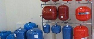
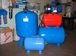
In appearance, all membrane tanks are similar to each other. There is an opinion that for the heating system - red, and for water supply - blue. But it is not entirely true, since some manufacturers use other colors.
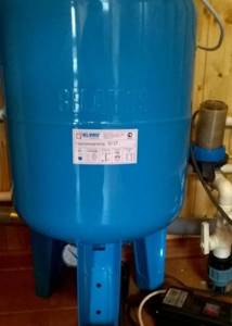
In fact, devices can be distinguished from each other only by technical characteristics, which are indicated on the nameplates on the devices themselves:
- All devices for water supply, including for hot water supply - low temperature - up to 80 degrees C, but high pressure - up to 12 Atm;
- expansion tanks for heating - high temperature - up to 120 degrees C, but low pressure up to 4 Atm.
How water storage schemes work
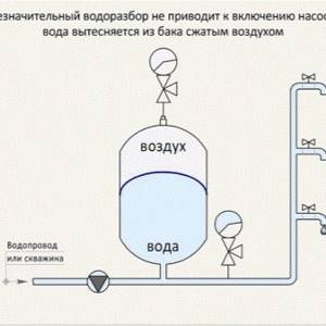
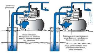
The hydraulic accumulator in the water supply circuit smoothes out pressure surges that occur when water is drawn from the system, i.e. when opening the tap, and reduce the number of pump starts, which should not be more than 50 times per hour.
When water is taken in the volume of a cup, the hydraulic accumulator will release this volume, the pressure in the system will drop, but not so much that the pressure switch turns on the pump. When taking a larger volume (for example, the volume of a bucket), the pressure will drop so much that the pump will turn on and fill the device.
The expansion tank in hot water supply and heating systems receives the excess volume of water that arises when it is heated.
If there were no such device, then in a heating closed circuit the pressure would very quickly rise above the critical one, since the liquid is practically not compressed. This would result in the release of water from the emergency pressure valve, which is usually set to a pressure of 3 atm.
In practice, if such a valve constantly lets water through, this indicates a malfunction of the storage device. If there is no emergency valve, then when heated, the weakest point of the system will be destroyed.
When an expansion tank is needed in a hot water supply system
This is a natural question, because hot water supply can be done in different ways. If there is a flow-through heater, for example a gas double-circuit boiler, which heats a stream of water directly when it is drawn in, then naturally an expansion tank is not needed.
If the system heats water in a large-capacity closed boiler (more than 100 liters), then the installation of an expansion tank in addition to a safety valve is required. Which is not the right thing to hope for, since it is not at all designed for frequent operation and with frequent activation it simply begins to leak.
How to choose the volume of a heating device
The main question that arises for the user is how much volume of such a water storage device is needed? At the same time, the user wants to purchase a smaller volume, since it is cheaper. But you need to purchase the one that suits your calculations.
How to choose the volume of a water supply accumulator
The more often the phases of operation and downtime of circulation pumps in the water supply system change, the higher the energy consumption and wear of components and parts in the hydraulic system equipment. Therefore, it is advisable to choose a hydraulic accumulator in order to reduce the number of starts of the pump electric motor. The main criterion in this choice is determining the optimal volume of the hydraulic tank. In this case, you can use both general (approximate) recommendations and very specific and accurate calculation methods.
To save energy and extend service life, the pump should be started no more than 30 times per hour. To roughly calculate the volume, you will have to take into account several more parameters:
- Pump capacity (QH). The average household pump has a capacity of approximately 2-3 m3/hour (2000-3000 l/hour);
- Useful volume of the hydraulic accumulator (VEF). This is the amount of liquid (water) that can be extracted from the hydraulic tank within min. and max. relay response pressure. In life, it makes up about 40% of the total capacity.
To ensure this condition, you need to select a GA with a total volume of at least:
V_min=Q_H/(30∙V_EF)=(2000…3000)/(30∙0.4)=170…250l
If the volume of water in the accumulator is used as a reserve, for example in the absence of electricity, a tank with a capacity of 24 liters or more is sufficient for a family of 1-2 people. For three consumers, tanks from 50 liters are recommended, and for four or more - from 100 liters.
It would seem that the larger the tank volume, the better. But do not forget that the water supply is just an additional bonus and the desire to increase it may have disadvantages:
- Such a hydraulic tank takes up a lot of space, which means you will have to have a large room to accommodate it.
- With a large volume and low consumption, the water in the tank may stagnate.
- It is not a fact that a minimum number of electric motor starts will extend the life of the pump
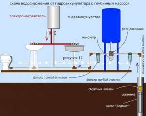
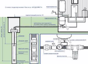
Installation diagram of a hydraulic accumulator to a submersible pump
The hydraulic tank connection diagram is similar to the previous one, the difference lies in the method of installing the pump.
The water supply system from a submersible pump uses a check valve that prevents water from leaving the membrane back into the hydraulic structure. The valve is mounted in front of the supply pipe on the pumping equipment; in some cases, an internal thread is made on the cover for this purpose.

For connection, a fitting of the required diameter with an external thread is used. After installing the valve, a supply water pipe of the required length is connected to it.
The length is determined quite simply: the end of the rope with a sinker is lowered into the hydraulic structure and the top point of the structure is marked. Next, the rope is raised and the length is measured from the sinker to the top point. The height from the point to the place where the pipe from the hydraulic structure is laid into the ground, as well as the length of the pumping equipment with the valve, is subtracted from the finished value. The optimal pipe length is when the equipment rises above the bottom of the well or well to a height of up to 35 cm.
Next, installation and adjustment of the hydraulic accumulator is carried out according to the standard scheme.
Connecting a hydraulic tank is a minimum of difficulties
Self-installation of a hydraulic accumulator into the water supply system does not cause any serious problems. If the device is connected to networks with surface-type pumping equipment, the procedure will be as follows:
- Measure the pressure inside the accumulator. Its value should be 0.2–1 bar less than the pressure of the pump start relay.
- Prepare a fitting to connect the relay, hydraulic tank, pressure gauge and pump into one circuit. Nuance. Take a fitting with five outlets. An “extra” input will be required to connect a water pipe.
- Buy a relay for adjusting the pressure, as well as a fluoroplastic sealing material (FUM tape) or tow with.
- Connect the fitting to the tank using a flange (it must have a bypass valve) or a rigid hose.
- Screw on all parts of the system one by one. The last connection is made to the pipe that leads to the pumping device.
The installed tank should be checked for leaks. If there are any, you need to additionally seal the joints of individual elements of the device with FUM tape or a suitable sealant.
When using a hydraulic tank in systems with a submersible pump, it is necessary to take into account that the latter is installed directly in the place from which water enters the residential building (in a well, well). This scheme is potentially unsafe. There is a high probability of water “rolling back” to the source. How to avoid this? Quite simply - by installing a special check valve. It is placed directly on the pump in front of the water pipe. The procedure for connecting the hydraulic tank will be similar to the diagram described above. But with one change. First you need to install a check valve. And only after that connect all elements of the hydraulic accumulator to the water supply network.
Choose and install a hydraulic tank in your home to never have problems with your autonomous water supply system!
A hydraulic accumulator is a membrane expansion tank suitable for use with drinking water in water supply systems.
What then can go wrong there, is there any point in overpaying for the brand and are all hydraulic accumulators really the same?
In this article we will look at how some hydraulic accumulators may differ from others, and most importantly, we will understand what factors influence their cost
.
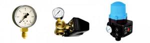
How to connect a hydraulic tank
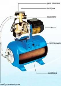
In addition to the pump and hydraulic tank, you will need a pressure switch and a pressure gauge. In accordance with the diagram for connecting the hydraulic accumulator to the water supply system, all these elements interact through a five-pin fitting. A tank with relays and instrumentation is installed in the boiler room or other room.
Dry-running relays and check valves are used as additional equipment for the system. These devices are responsible for ensuring that there is always water in the pipes and that it does not flow into the well or borehole. But this is when we are talking about individual water supply systems. After installation, it is necessary to carry out commissioning work, which consists of checking the tightness of connections and adjusting the hydraulic tank.
The established operating parameters are 1.7 bar. At the same time, the pumping equipment is turned on. The relay is set so that it switches off at 2.8 bar. These parameters are considered ideal for most models. Information can be found in the operating instructions for the hydraulic accumulator with pump.
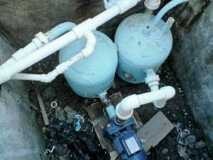
Connection to a pumping station
In this case, work on connecting the hydraulic accumulator to an autonomous water supply system is carried out simultaneously with the installation of automation and adapters. The most common installation cases require the following components:
- pressure gauge;
- five-inlet fitting;
- switching hydraulic relay (pressure switch).
If a submersible pump is used to draw water, the well piping must be equipped with a check valve and a dry inlet relay. If a simpler surface centrifugal pump is used to pump water, it is cheaper and more expedient to buy an assembled pumping station rather than install individual elements. The second option is preferable for those who have little experience but want to install the pump themselves.
Two hydraulic tanks for one pump
Connecting two (or more) hydraulic tanks is a common problem for people faced with a forced increase in water consumption. If the volume of one tank turns out to be too small, installing an additional hydraulic accumulator is not very burdensome.
Additional elements can be installed parallel to the existing system: it is enough to use another adapter fitting, flexible hose or water pipe. A system with two (or more) tanks is both a rational solution and an excellent safety net. If the membrane fails in one of the tanks, you can still use the pump, but not in intensive mode. Such a system will provide enough time to replace the faulty unit.
To submersible pump
You can guess that we are talking about a pump that is immersed in the aquifer of a well or well. For uninterrupted water supply, such a system must be equipped with a check valve: this device will not allow the pumped out water to return to the bottom of the well after use. Accordingly, the pump will not run idle and will last much longer.
In most cases, the check valve is already installed on the pump; additional installation may be required during the repair process. To avoid being left without water for an indefinite period of time, it is recommended to purchase a pump with a spare valve, which is sold separately or supplied with the pump.
Another important point is the quality of the pressure pipeline: since the pipe lies at a fairly large depth, a possible breakdown may not be noticed immediately.
The first sign of problems with the pipeline is a sharp drop in pressure; the accumulator takes longer to fill with water; over time, this gap may increase.
To surface pump
Connecting a hydraulic accumulator to a system with an external centrifugal pump also has its own nuances, namely:
- first of all, you need to check the internal pressure of the tank: it should not exceed 1 bar;
- To prepare for connection, you will need a five-pin fitting. This small but very important part combines the accumulator itself, a pipeline, a pressure switch, a pressure gauge and an external pump. Before the actual installation process, you need to stock up on sealing materials (sealant or plumbing tape);
- to connect the fitting to the tank, use a rigid hose or flange with a bypass valve;
- after installing the tank, it is worth installing the remaining elements: pressure gauge, relay, water supply leading to the pump unit;
- before starting operation, a series of on and off cycles should be carried out to identify possible leaks;
- if something goes wrong, you need to find out the cause of the problem and, if necessary, repeat the entire installation cycle again.
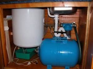
Connection to water heater
The hydraulic accumulator in a system with a storage water heater acts as an expansion tank. As water heats up, it increases in volume, which also increases the load on the water supply. Since pressure increases in a confined space, the process can become very critical, and the temperature decrease is unacceptable. There is a need to transfer this excess pressure somewhere. This is where the hydraulic accumulator comes to the rescue. Excess heated water will go into the hydraulic tank, which will normalize the pressure in the system. Further, the water from the expansion tank can be used for domestic purposes.
How a hydraulic accumulator works - simple and reliable design
A stable functioning water supply system of a private home is the merit of its owner. People who have experienced the installation and operation of autonomous water supply networks can imagine how difficult it is to avoid interruptions in the water supply in such complexes. Sometimes just one pressure surge is enough for expensive equipment connected to the water supply (for example, a water heater, a dishwasher) to fail. There is only one solution to such a problem - installing a hydraulic accumulator. It maintains a given pressure in the system, creates a certain supply of water and eliminates the risk of breakdown of household electrical equipment.
The need to install such a device is obvious.
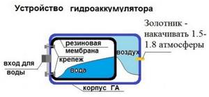
The design of the hydraulic accumulator is quite simple. It is made in the form of a metal tank, inside of which a rubber membrane is installed. The latter is visually similar to a pear. The membrane is fixed to the hydraulic tank body by means of a special flange with a pipe. Water accumulates in the bulb under pressure. The space between the battery housing and the membrane is filled with compressed air (if we are talking about household devices) or an inert gas composition (industrial hydraulic tanks). The pressure in the system is maintained at 1.5–3 bar. Air can be pumped into a hydraulic accumulator at home using a regular car or even bicycle pump.
The devices under consideration are usually divided into three types:
- 1. For cold water supply systems. The device supplies water and stores it, protects pumping equipment from early wear and tear caused by frequent system switching on and off, and protects electrical equipment in the house from water hammer.
- 2. For hot water. Such a hydraulic accumulator for water supply systems can operate in high-temperature environments without problems.
- 3. Expansion tanks. They are designed for closed water heating systems.
The design and operating principle of all these devices are identical. We will talk about how such equipment functions further.
How does a hydraulic accumulator work?
The principle of the hydraulic accumulator is simple, like everything ingenious. A rubber gasket of conical, pear-shaped or other shape is inserted into the body of the metal tank.
The gasket or membrane is most often made of butyl, which has a significant margin of strength and is resistant to constant stretching and exposure to water.
This material is also characterized by high antibacterial properties and meets all hygiene standards. The water entering the container is retained by this gasket and does not come into contact with the walls of the metal body.
A nipple is installed on the back of the housing, which allows air to be pumped into the container.
Image gallery
Photo from
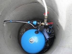
Hydraulic tank as part of a factory-assembled pumping station
Hydraulic accumulator in a circuit with a submersible pump
Functions and purpose of hydraulic tanks in water supply
Rules for proper operation of hydraulic accumulators
Water and air are separated by a gasket. By pumping or bleeding air, you can regulate the pressure it exerts on the water. As a result, water enters the system under pressure, and this provides the necessary pressure.
A mandatory element for a hydraulic accumulator is a pressure gauge, which is used to control the current pressure in the tank. The optimal pressure in the air compartment of the hydraulic accumulator is considered to be 1.5-2.0 atmospheres.
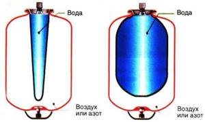
The diagram clearly shows the structure of the hydraulic accumulator. Water enters the upper part, which is held by a rubber membrane, and air is pumped into the lower part, which provides the necessary water pressure
Wherever good pressure is needed, installing a hydraulic accumulator will be more than relevant. And the requirements for good pressure are constantly increasing.
For example, for normal operation of an automatic washing machine or dishwasher, at least 0.7-2 atmospheres may be needed. A shower cabin with hydromassage or the famous bathtub with a jacuzzi will work normally only at four atmospheres.
It’s worth noting right away that excess pressure in the plumbing system is not the most useful phenomenon, since this creates an additional and completely unnecessary load on the structure.
This reduces their service life and leads to leaks, breakdowns and other problems. Although during pressure testing of the system the pressure can reach even 10 atmospheres, performance indicators are best left at 4-5 atmospheres.
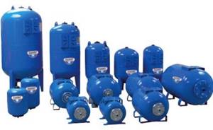
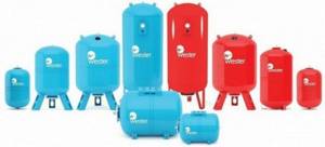
Hydraulic accumulators vary in volume, and they can also be oriented horizontally or vertically. Hydraulic tanks designed to operate at high temperatures are designed for heating systems
Even if the house does not have modern household appliances that are sensitive to water pressure in the water supply, a hydraulic accumulator can still come in handy. On the upper floors of high-rise buildings, the water pressure in the water supply can be very, very weak. A hydraulic accumulator can effectively solve this kind of problem.
The capacity of the hydraulic accumulator can vary between 5-100 liters. Of course, these are very modest numbers to store water. If there is a need to always have a solid supply of water, it is better to use a storage tank of sufficient volume.
When organizing an autonomous water supply, a hydraulic accumulator is used in combination with a surface or submersible pump. The device pumps water into the tank until the pressure reaches a certain, predetermined level. After this, the equipment turns off automatically.
The water decreases, the pressure decreases, and reaches a minimum level. At this moment, the pump turns on again and runs until the previously emptied container is filled with water.
To regulate the operation of such a system, a pressure switch is used. This allows you to reduce the number of switches on/off of pumping equipment to a minimum, which significantly increases its service life.
The inlet for supplying water to the accumulator is equipped with a special pipe, which is installed on a threaded connection.
Image gallery
Photo from
Accumulator housing material
Flange with threaded fitting
Hydraulic tank air valve - nipple
Hydraulic accumulator platform
Modern models are relatively easy to disassemble and then reassemble, performing the necessary maintenance, replacing parts or other types of repairs. If the accumulator is installed correctly, then for its maintenance there is no need to drain water from the water supply system.

This table can be used to calculate the volume of the hydraulic tank for a specific situation, based on the predicted operating conditions (+)
When choosing a hydraulic accumulator, you should pay attention to the diameter of the pipe and compare it with the dimensions of the water pipe. Experts assure that the more accurate these indicators are, the less hydraulic losses there will be in the system. If the diameters of the structures do not match, you will have to use an adapter.
Water tends to evaporate, which can affect the pressure readings in the device. To bleed off such excess air, a valve is installed on large-capacity hydraulic accumulators - about 100 liters.
Small volume models do not have such a device. It is recommended to install a valve or tee in the system, which will shut off the water supply to the water supply and allow excess air to be removed.
Balloon or membrane
Hydraulic accumulators are divided into two main types - membrane and balloon. The principle of operation of both types is similar - an elastic film of rubber expands or contracts under pressure from water and compressed air. The main difference is that in a membrane tank, water coming from the well comes into contact with the metal walls of the tank, which can potentially lead to corrosion. In a tank with a rubber cylinder, water comes into contact only with the cylinder itself, without touching the metal walls. The absence of conditions for the development of corrosion extends the life of the balloon accumulator.
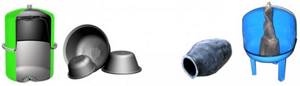
An additional convenience is that the cylinder, unlike the membrane, is a replaceable part. Carrying out the replacement will not cause any difficulties - even a non-specialist can do it. As a result, servicing a hydraulic accumulator with a cylinder will be cheaper. Taking into account the above factors of practicality and reliability, cylinder accumulators are the optimal solution for individual water supply.
An important factor when choosing a hydraulic accumulator is the cost of spare parts
Please note that some manufacturers may unreasonably inflate the price of components. For example, a rubber cylinder can cost half or even more of the cost of the entire hydraulic accumulator
Selection of hydraulic accumulator
The volume of the selected accumulator tank must be greater than or equal to the volume obtained as a result of the calculation. There are no negative consequences from overestimating the volume of the hydraulic accumulator beyond the calculated value, no matter how much it is exceeded.
When selecting a hydraulic accumulator, you should take into account its temperature and strength characteristics. The maximum pressure of the tank must be greater than or equal to the maximum pressure at its connection point.
If the installation of hydraulic accumulators is planned indoors, then it should be taken into account that tanks with a diameter of more than 750 mm and a height of more than 1.5 m may not fit through the doorway, and mechanization will be required to move them. In this case, it is better to give preference to not one, but several hydraulic accumulator tanks of smaller capacity.
When choosing a hydraulic accumulator, you should remember that the volume of water stored in it is on average 40-50% of the tank volume.
Installation of a heat accumulator
Improving the heating operation with additional devices with your own hands will make it necessary to carry out the following work:
Make a detailed diagram
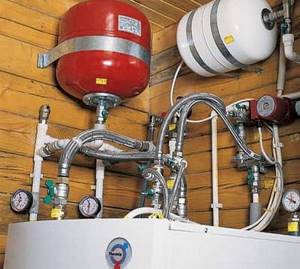
When developing a drawing, you need to take into account where the heating accumulator is located, the insulating layer, the height of the battery tank, the presence of drainage for water disposal - factors for reducing heat loss; Integrate a collector-distributor into the system, ensuring that the various systems are connected correctly; After connecting the pipeline parts, check the tightness of the connections; Connect the storage tank; Connect the circulation pump; After completing the assembly work with your own hands, test the tightness and correctness of the connections. To prevent the pump from turning on every time a tap is opened in the house, a hydraulic accumulator is installed in the system
It contains a certain volume of water, sufficient for a small flow rate. This allows you to practically get rid of short-term pump starts. Installing a hydraulic accumulator is not difficult, but a number of devices will be required - at a minimum - a pressure switch, and it is also desirable to have a pressure gauge and an air vent
To prevent the pump from turning on every time a faucet is opened in the house, a hydraulic accumulator is installed in the system. It contains a certain volume of water, sufficient for a small flow rate. This allows you to practically get rid of short-term pump starts. Installing a hydraulic accumulator is not difficult, but you will need a few more devices - at least a pressure switch, and it is also desirable to have a pressure gauge and an air vent.
Installation rules
When installing a hydraulic accumulator, you must strictly adhere to certain rules.
The first thing to do is to select a site in the heating network where the device will be installed.
Experts strongly advise mounting the expansion tank in the return pipe through which cooled water circulates.
Important ! The unit must be installed in front of the pumping equipment.
In order to ensure maximum protection of the network from sudden changes in pressure of the working fluid, a safety valve must be installed at the outlet of the heating device.
The valve has the same purpose as a hydraulic accumulator , but it is able to withstand higher pressure drops.
The expansion tank normalizes the operation of the heating system during minor surges in water pressure.
Before proceeding with installation , you need to select a location for installing the device. Do not forget that the device must be freely accessible; nothing should prevent you from getting to the air compartment control valve.
Shut-off and control valves cannot be installed between the expansion tank and the pump; they can significantly change the hydraulic resistance.
In the room where the hydraulic accumulator will be located , the air temperature must be at least 0 degrees. The surface of the device must not be exposed to mechanical loads.
The activation of the gearbox to remove air from the heating system of a private house must be carried out in accordance with the parameters of the heating system.
If you follow all the above recommendations , you will be able to install the expansion tank on your own, without outside help.
Why you need a hydraulic accumulator in heating systems, how to install and configure it - we suggest you watch it in the video.
Optimal pressure in the accumulator
The air pressure in the hydraulic tank in the absence of water is one of the main operating parameters. This parameter is different for each hydraulic accumulator and is indicated in its technical data sheet. Small fluctuations from the nominal value are allowed, but significant excess or decrease in pressure should be avoided, as the service life of the rubber cylinder (membrane) is reduced. For the water supply system to operate, the pump activation pressure must be at least 0.5 bar higher than the operating air pressure in the accumulator.
The nominal pressure may be affected by the number of storeys in the building. For example, if the accumulator is located in the basement of a two-story building, then the minimum pressure in the water supply system should be 2 bar. 1 bar of pressure is needed to raise water to a height of 10 m, another 1 bar is needed to create the required water pressure in the consumer’s tap. In our case, 10 m is the average height difference between the basement and the second floor. Taking into account the pressure of 0.5 bar created by the well pump, the operating pressure in the accumulator should be equal to 1.5 bar.
The pressure values for turning on and off the well pump can be set programmatically in the automatic control unit. The sensor is a pressure switch. Correctly set pressure values will reduce the frequency of pump activation and maintain the required pressure in the water supply system. Effective operation of the accumulator occurs if the difference between the pressure on and off the pump is from 1.5 to 4.5 bar.
Conclusions and useful video on the topic
An overview of the operation of a 50-liter hydraulic accumulator is presented in the following video:
This video clearly demonstrates the procedure for adjusting the pressure in the hydraulic tank and setting the pressure switch:
The advantages of using a hydraulic accumulator are obvious, so this device is increasingly being used both in private houses outside the city and in metropolitan apartments. If the unit is installed and connected correctly, it will work for many years without breakdowns or interruptions, providing the family with high-quality water supply.
Do you have experience in installing and connecting a hydraulic accumulator yourself? Please share information with our readers, tell us about the features of setting up and operating the hydraulic tank. You can leave comments in the form below.
Functions, purpose, types
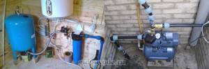
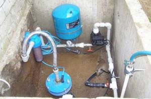
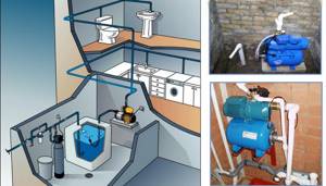
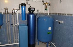
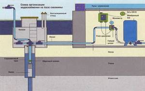
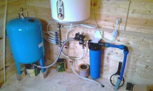
Installation location - in a pit or in a house
In the water supply system of a private house without a hydraulic accumulator, the pump turns on whenever water flows somewhere. These frequent starts lead to wear and tear on the equipment. And not only the pump, but the entire system as a whole. After all, every time there is an abrupt increase in pressure, and this is a water hammer. To reduce the number of pump starts and smooth out water hammer, a hydraulic accumulator is used. The same device is called an expansion or membrane tank, a hydraulic tank.
Purpose
We found out one of the functions of hydraulic accumulators - to smooth out water hammer. But there are others:
It is not surprising that most private water supply systems have this device - there are many advantages from its use.
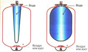
Kinds
The hydraulic accumulator is a tank made of sheet metal divided into two parts by an elastic membrane. There are two types of membrane - diaphragm and balloon (bulb). The diaphragm is attached across the tank, a pear-shaped cylinder is secured at the inlet around the inlet pipe.
According to their purpose, they are of three types:
- for cold water;
- for hot water;
- for heating systems.
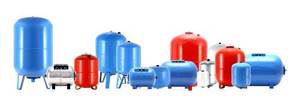
Hydraulic tanks for heating are painted red, tanks for water supply are painted blue. Expansion tanks for heating are usually smaller in size and lower in price. This is due to the membrane material - for water supply it must be neutral, because the water in the pipeline is potable.
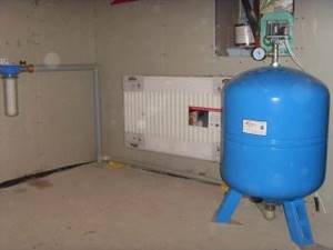
Depending on the type of arrangement, hydraulic accumulators can be horizontal or vertical. Vertical ones are equipped with legs; some models have plates for hanging on the wall. It is the elongated upward models that are most often used when independently creating water supply systems for a private home - they take up less space. The connection of a hydraulic accumulator of this type is standard - through a 1-inch outlet.
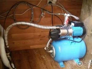
Horizontal models are usually equipped with pumping stations with surface-type pumps. Then the pump is placed on top of the tank. It turns out compact.
Principle of operation
Radial membranes (in the form of a plate) are used mainly in gyroaccumulators for heating systems. For water supply, a rubber bulb is usually installed inside. How does such a system work? As long as there is only air inside, the pressure inside is standard - the one that was set at the factory (1.5 atm) or that you set yourself. The pump turns on, begins to pump water into the tank, and the pear begins to increase in size. Water gradually fills an increasingly larger volume, increasingly compressing the air that is located between the wall of the tank and the membrane. When a certain pressure is reached (usually for one-story houses it is 2.8 - 3 atm), the pump is turned off, and the pressure in the system stabilizes. When you open a tap or other water flow, it comes from the accumulator. It flows until the pressure in the tank drops below a certain level (usually about 1.6-1.8 atm). After which the pump turns on, the cycle repeats again.

If the flow rate is large and constant - you are filling a bathtub, for example - the pump pumps water in transit, without pumping it into the tank. The tank begins to fill after all the taps are closed.
A water pressure switch is responsible for turning the pump on and off at a certain pressure. In most hydraulic accumulator piping schemes, this device is present - such a system operates in optimal mode. We’ll look at connecting the hydraulic accumulator a little lower, but for now let’s talk about the tank itself and its parameters.
Large tanks
The internal structure of hydraulic accumulators with a volume of 100 liters and above is slightly different. The pear is different - it is attached to the body both at the top and bottom. With this structure, it becomes possible to fight the air that is present in the water. To do this, there is an outlet in the upper part into which you can connect a valve for automatic air release.
Purpose of the hydraulic accumulator
Hydraulic accumulators are often confused with expansion tanks, even despite the fundamentally different problems that these devices solve. An expansion tank is needed in heating and hot water supply systems, since the coolant, moving through the system, inevitably cools and its volume changes. The expansion tank is set up when the system is “cold”, and when the coolant warms up, its excess, which is formed due to expansion, has somewhere to go.
The hydraulic accumulator is needed for completely different purposes: if it is not installed in the water supply system, the pump will be activated every time a tap is opened. If this happens often, then not only the pump, but the entire system wears out faster, since each time the pressure increases abruptly - a so-called water hammer occurs.
As a result, a hydraulic accumulator is installed with the aim of getting rid of water hammer and extending the service life of the system as a whole. In addition, the accumulator has other functions:
- Creates a certain supply of water (useful if there is a power outage).
If there are frequent interruptions in water supply, the hydraulic accumulator can be combined with a storage tank
- Reduces the frequency of pump startup. The reservoir is filled with a small volume of water. If the flow rate is small, for example, you need to wash your hands or wash your face, water begins to flow from the tank, while the pump remains turned off. It is activated after very little water remains;
- Maintains stable pressure in the system. In order for this function to be performed properly, an element called a water pressure switch is provided, which is capable of maintaining a given pressure within strict limits.
All the advantages of hydraulic accumulators make this device an indispensable element of any autonomous water supply system in country houses.
What is a hydraulic accumulator
A hydraulic tank (or hydraulic accumulator) is a water container with a rubber elastic membrane (resembling a pear) located inside the container and having a sealed connection to the metal body of the tank. This connection is made using a flange with a threaded connection to connect the device to the water supply. The cavity between the membrane and the metal body of the hydraulic tank is filled with compressed air, usually the pressure is 1.5-2 bar. Hydraulic accumulators are used to maintain constant pressure and create a water reserve in domestic or industrial conditions. It is this unit that provides the required pressure in the system when the pump is turned off.
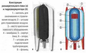
Fig.1.
Hydraulic accumulator structure 1 – metal body; 2 – rubber membrane; 3 – flange with valve (passes air); 4 – nipple for pumping air into free space; 5 – cavity for compressed air; 6 – supports; 7 – platform for the pump. More details about the design of the hydraulic tank in the video: Return to content
Calculation of expansion tank volume - Calculator
Calculator for calculating the volume of a membrane expansion tank for a heating system:
Method for calculating the volume of a membrane expansion tank for a heating system:
The calculation presented below is intended for individual heating systems and is significantly simplified. Its accuracy is 10%. We think this is quite enough
1. Let's determine what type of liquid you will use as a coolant. For an example of calculation, we will take water as a coolant. The coefficient of thermal expansion of water is assumed to be 0.034 (this corresponds to a temperature of 85 o C)
2. Determine the volume of water in the system. It can be approximately calculated depending on the boiler power at the rate of 15 liters per kilowatt of power. For example, with a boiler power of 40 kW, the volume of water in the system will be equal to 600 liters
3. Determine the maximum permissible pressure in the heating system. It is set by the response threshold of the safety valve in the heating system
4. The calculations also use the value of the initial air pressure in the expansion tank Po. The Po pressure must not be less than the gyrostatic pressure of the heating system at the location of the expansion tank
5. The total expansion volume V can be calculated using the formula:
6. You need to select a tank by rounding the calculated volume up (a larger tank will not hurt)
7. Now let’s select a tank that provides compensation for this volume. Considering that the water filling coefficient of an expansion tank with a fixed, non-replaceable membrane under these conditions is 0.5 (table), then an 80-liter expansion tank is suitable for the system considered:
80 liters x 0.5 = 40 liters
Filling factor (useful volume) of the expansion membrane tank
| Maximum pressure in the system Pmax, bar | Initial pressure in the tank, Po bar | ||||||||
| 0,5 | 1,0 | 1,5 | 2,0 | 2,5 | 3,0 | 3,5 | 4,0 | ||
| 1 | 0,25 | — | — | — | — | — | — | — | |
| 1,5 | 0,40 | 0,20 | — | — | — | — | — | — | |
| 2,0 | 0,50 | 0,33 | 0,16 | — | — | — | — | — | |
| 2,5 | 0,58 | 0,42 | 0,28 | 0,14 | — | — | — | — | |
| 3,0 | 0,62 | 0,50 | 0,37 | 0,25 | 0,12 | — | — | — | |
| 3,5 | 0,67 | 0,55 | 0,44 | 0,33 | 0,22 | — | — | — | |
| 4,0 | 0,70 | 0,60 | 0,50 | 0,40 | 0,30 | 0,20 | — | — | |
| 4,5 | — | 0,63 | 0,54 | 0,45 | 0,36 | 0,27 | 0,18 | — | |
| 5,0 | — | — | 0,58 | 0,50 | 0,41 | 0,33 | 0,25 | 0,16 | |
| 5,5 | — | — | 0,62 | 0,54 | 0,47 | 0,38 | 0,30 | 0,23 | |
| 6,0 | — | — | — | 0,57 | 0,50 | 0,42 | 0,35 | 0,28 | |
Peculiarities
The hydraulic tank is called a hydraulic accumulator or membrane tank. It is used to maintain a stable pressure level in the water supply system. The product also protects the pump from wear and the drainage system itself from water hammer. Thanks to the hydraulic tank, you can use water even in the absence of voltage.
Advantages of vertical hydraulic tanks:
- Protection of the pump from early wear.
- Maintaining stable pressure in the water supply system.
- Protection against water hammer that may occur during the start-up of alluvial equipment. Water hammer can damage the pipeline.
- Maintaining water reserves in the system.
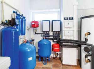
Vertical type hydraulic accumulators have disadvantages, which include complex installation. Installation will require effort and some skill.
Operating principle of a hydraulic accumulator
A hydraulic accumulator works like this. The pump supplies water under pressure to the accumulator membrane. When the pressure threshold is reached, the relay turns off the pump and water stops flowing. After the pressure begins to drop during water intake, the pump automatically turns on again and supplies water to the accumulator membrane. The larger the volume of the hydraulic tank, the more effective the result of its operation. The response of the pressure switch can be adjusted.
During operation of the accumulator, air dissolved in water gradually accumulates in the membrane, which leads to a decrease in the efficiency of the device. Therefore, it is necessary to carry out preventive maintenance on the hydraulic accumulator by bleeding off the accumulated air. The frequency of maintenance depends on the volume of the hydraulic tank and the frequency of its operation, which is approximately once every 1-3 months.
The principle of operation of the hydraulic tank and how it all happens
When the pumping equipment is turned on, water begins to flow into the membrane. The volume of the pear increases. This leads to the fact that the air in the accumulator housing (outside the membrane) is compressed and forms some pressure. When the specified value is reached, the electric pump is switched off at the command of the control relay. Compressed air presses on the water in the bulb and pushes it through the water supply. The consumer opens the tap. Water begins to flow through it, coming from a hydraulic tank under a given pressure.
After some time, there is less water in the membrane. Because of this, the pressure level also decreases. When it becomes minimal, the relay is activated again and the pump automatically starts. Then everything goes according to the scheme already described above. The pumping equipment starts more often, the smaller the hydraulic tank is used. The optimal capacity of a hydraulic accumulator for domestic use is 100 liters. In this case, the relay operates no more than 5–15 times in 60 minutes. With such indicators, wear of hydraulic equipment will be minimal
It is important to understand that more frequent pump starts lead to premature wear of the membrane and other battery elements
Water entering household hydraulic tanks most often rises from wells or specially equipped wells. This liquid is characterized by increased oxygen saturation. It can accumulate in the pear, released during the functioning of the home plumbing. Oxygen must be periodically removed from the system. For these purposes, in many models of hydraulic accumulators, a special valve is mounted on the body (in its upper part). If necessary, it independently releases excess oxygen.
Active use of the hydraulic tank often causes a decrease in air pressure. No equipment is insured against such natural wear and tear. Experts recommend completely emptying the battery and checking the pressure reading every 10–12 months. This simple procedure will guarantee comfortable use of water supply in a private home.
The most popular hydraulic accumulators for heating
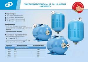
The number of membrane expansion tanks offered for sale is so large that you can easily get confused when choosing. Among the most famous manufacturers who have long confirmed the high quality of their products are brands such as:
- Reflex;
- Aquasystem;
- Zilmet;
- Wester;
- TIM.
A study of consumer demand showed the following 5 popular models:
- Reflex NG 100;
- Aquasystem VAV;
- Wester WAO 50;
- Stout STH 006 00050;
- Gilex 100.
This listing is not an advertising recommendation. It’s just that these hydraulic accumulators are leading the market in terms of sales volumes over the past year.
Accumulator volume
Do not buy a hydraulic accumulator based on what your friends or neighbors in the country have installed. Perhaps this model will not be effective for you. The volume of the hydraulic accumulator (like all other equipment!) should be selected only on the basis of the results of hydraulic calculations. The number of models on the market is quite large.
Is there an optimal hydraulic tank volume? As we have already said, only a hydraulic calculation can accurately indicate a specific model of hydraulic equipment that is optimally suited to your conditions. But the number of typical volumes for various models of hydraulic tanks is not so large. That is, if, according to the calculation results, you need a tank with a volume of 51.5 liters, then you will not be able to find such a tank on sale. You will be advised to purchase a 60 liter hydraulic tank. Extra liters of volume will not harm, and will even slightly increase the water supply and reduce the number of pump starts.
The experience of engineers selecting and installing water-lifting equipment tells us the following:
- A hydraulic accumulator with a volume of 25 liters can be installed in a water supply system for three consumers with a borehole pump productivity of 2 m3/h.
- in a system with a number of consumers of 4-8 and a pump capacity of 3.0-3.5 m3/h, a hydraulic tank with a volume of 60 liters is optimal.
- if the number of consumers is more than 10 and the pump capacity is 5 m3/h, then the optimal tank volume will be 100 liters.
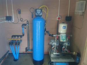
Order installation of a hydraulic accumulator
If you need help with choosing and installing a hydraulic tank, contact our specialists. We will select a model for you taking into account the optimal parameters. We will deliver the equipment to your site and install it in accordance with all the rules.
In our company you can order well piping. Then we will select and install a pump, hydraulic accumulator and automation. We will carry out equipment setup and commissioning. We will issue a warranty for the installed equipment.
To order installation of a hydraulic tank or piping of a well, leave a request on the website. A specialist will call you back and answer any questions.
16.11.2019 11:42:43
6293
Recommended Articles
Is there a difference between vertical and horizontal hydraulic accumulators?
The tanks described in the article are mounted in two ways: vertically and horizontally. The specific type of hydraulic accumulator should be selected based on how compactly it will fit into the area that will be allocated for its installation. In addition, in vertical and horizontal devices, air is removed from the membrane differently
It is important. In vertical devices, the release of accumulated oxygen is carried out using a safety valve (we have already mentioned it)
But in horizontal ones it is necessary to additionally install a special pipeline to remove air. Structurally, the additional line consists of a ball valve, a drain and a nipple (it is called an outlet valve).
Please pay attention to the following nuances:
- Vertical accumulators with a volume of less than 100 l are never equipped with a safety valve. Bleeding air in such devices is carried out by completely emptying them.
- It makes more sense to connect horizontal hydraulic tanks to external pumps, and vertical ones to submersible ones installed inside a room specially designated for them.
The ability to bleed air must be present in any hydraulic tank. If you do not free the equipment from the oxygen accumulated in it, air pockets will very quickly appear in the water supply. They will not allow you to effectively operate your home water supply system.
Hydraulic accumulator device
The sealed body of this device is divided by a special membrane into two chambers, one of which is intended for water and the other for air.
Water does not come into contact with the metal surfaces of the body, since it is located in a water chamber-membrane made of a strong butyl rubber material that is resistant to bacteria and meets all hygienic and sanitary standards for drinking water.
The air chamber contains a pneumatic valve, the purpose of which is to regulate pressure. Water enters the accumulator through a special threaded connection pipe.
The hydraulic accumulator device must be mounted in such a way that it can be easily disassembled in case of repair or maintenance, without draining all the water from the system.
The diameters of the connecting pipeline and the pressure pipe should, if possible, coincide with each other, then this will avoid unwanted hydraulic losses in the system pipeline.
In the membranes of hydraulic accumulators with a volume of more than 100 liters there is a special valve for bleeding air released from the water. For small-capacity hydraulic accumulators that do not have such a valve, the water supply system must have a device for bleeding air, for example, a tee or tap that shuts off the main line of the water supply system.
In the air valve of the hydraulic accumulator, the pressure should be 1.5-2 atm.
Connecting the accumulator to the system
Typically, the water supply system of a private home consists of:
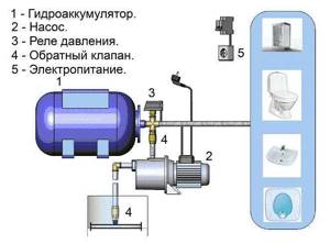
This scheme may also include a pressure gauge for operational pressure control, but this device is not necessary. It can be connected periodically to carry out test measurements.
With or without five-pin fitting
If the pump is of a surface type, the hydraulic accumulator is usually placed next to it. In this case, the check valve is installed on the suction pipeline, and all other devices are installed in one bundle. They are usually connected using a five-pin fitting.
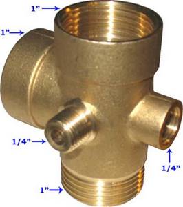
It has terminals with different diameters, just for the devices used for tying the hydraulic accumulator. That’s why the system is most often assembled on its basis. But this element is not at all necessary and everything can be connected using ordinary fittings and pieces of pipe, but this is a more labor-intensive task, and there will be more connections.
How to connect a hydraulic accumulator to a well - diagram without a five-pin fitting
With one inch outlet, the fitting is screwed onto the tank - the pipe is located at the bottom. A pressure switch and pressure gauge are connected to the 1/4 inch outlets. The remaining free inch terminals are connected to the pipe from the pump and wiring to consumers. That's all for connecting the gyroaccumulator to the pump. If you are assembling a water supply circuit with a surface pump, you can use a flexible hose in a metal winding (with inch fittings) - it is easier to work with.
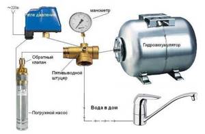
A visual diagram of connecting the pump and accumulator - use hoses or pipes where necessary
As usual, there are several options, the choice is yours. The hydraulic accumulator is connected to the submersible pump in the same way. The whole difference is where the pump is installed and where the power is supplied, but this has nothing to do with the installation of the accumulator. It is placed in the place where the pipes from the pump enter. Connection is one to one (see diagram).
How to install two hydraulic tanks on one pump
When operating the system, sometimes owners come to the conclusion that the available volume of the accumulator is not enough for them. In this case, you can install a second (third, fourth, etc.) hydraulic tank of any volume in parallel.
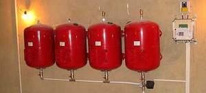
There is no need to reconfigure the system; the relay will monitor the pressure in the tank on which it is installed, and the viability of such a system is much higher. After all, if the first accumulator is damaged, the second one will work. There is another positive point - two tanks of 50 liters each cost less than one of 100. The point is that the technology for producing large-sized containers is more complex. So it is also more economical.
How to connect a second accumulator to the system? Screw a tee onto the input of the first one, connect the input from the pump (five-pin fitting) to one free output, and connect the second container to the remaining free one. All. You can test the circuit.
To avoid depressurization of joints and heating equipment, a hydraulic accumulator or expansion tank is installed in the system. This unit provides constant pressure - when it expands, water flows into it and does not harm the system.
How to choose a hydraulic accumulator
When it comes to choosing, then thoughts arise about whether to make a hydraulic accumulator for heating with your own hands. In fact, there is no difficulty in this, at least if you are not going to install additional low-temperature heating and hot water circuits, as well as electric heating. The main thing is that the container is sealed and, if possible, insulated. The insulation layer will reduce heat loss, which will increase the efficiency of the heat accumulator. Below is the simplest design of a heat accumulator:
The most primitive accumulator circuit
The shape of the tank can be any, as long as the pressure in the circuit does not exceed three atmospheres. And in an autonomous heating system this condition is met. The pressure in the hydraulic accumulator of the heating system is the same as in the entire circuit. Even automatic emergency valves are designed to withstand this pressure. So the shape depends more on where you put it. In general, do whatever is convenient for you.
You can add a DHW circuit. To do this, you need to weld two pipes into the upper part of the tank. A spiral is attached to them from the inside, through which water will circulate. The spiral must be in the upper part, as it is warmer there. The scheme is approximately like this:
Diagram of a hydraulic accumulator with a DHW circuit
The longer the tube you insert to heat water for household needs, the more it will warm up. The advantage of a homemade buffer tank is that you can always improve it, for example, add heating elements that will operate from the network or from solar panels. In this case, it is better to place heating elements in several places. This arrangement of additional heaters allows for a more even distribution of temperature in the tank.
Hydraulic accumulator for water: installation
As already noted, hydraulic accumulators are considered not particularly suitable for heating and hot water supply. In addition, it is worth considering that problems can arise if even the highest quality equipment is installed incorrectly.
Why and what kind of tank has problems:
- It is impossible to drain the water because the drain is clogged;
- After the pump stops, the water goes back to the source;
- The tank doesn't fill up enough;
- The nipple begins to leak;
- The pump does not hold pressure, and it drops sharply rather than gradually;
- Uploading is very slow and the like.
All these malfunctions are associated with illiterate installation. In order to be confident in the serviceability of the entire system after assembly or purchase and subsequent installation, it is worth conducting testing. It is necessary to check the integrity of the structure and connections. Using a car pressure gauge, the pressure inside the container is measured. Connection is made to the outlet in the pump and the hole in the water supply system, with the additional installation of a safety valve.
The accumulator tank will be filled with water, gradually, so that the membrane does not rupture. At this point, you need to carefully monitor the data on the pressure gauge and monitor the correct installation and operation of the relay. The pump is turned on and the pressure is monitored, which should decrease by no more than 10% upon start-up. For preventative purposes, it is advisable to check the general condition of the device once a month, which will help to find problem areas in the equipment as quickly as possible and eliminate them at the initial stage of failure.
Design and principle of operation
The hydraulic accumulator looks like a small box, available in different shapes with additional elements responsible for control - these parts are located under the cover. The battery is attached to a specific outlet of the fitting (or tee) of the container. Its mechanism is equipped with springs - they are responsible for adjusting and turning the nuts.
It is worth taking a closer look at the principle of operation of a hydraulic accumulator.
- The springs in this part are connected to a membrane that responds to pressure. Increasing the parameters leads to compression of the spiral, and decreasing them leads to compression.
- A group of contacts designed to respond to the mentioned processes by closing or opening contacts signals this to the pump. The connection diagram in all cases provides for connecting its electrical cable to the unit.
- As the storage tank fills, the pressure increases. The spring releases the pressure power, the equipment is activated in accordance with the set values - it deactivates the pump, giving it the appropriate command.
- The pressure weakens as the liquid is consumed. The moment the system detects this, the engine starts.
The hydraulic accumulator includes several main components.
- the housing is usually divided by a membrane into two separate chambers: one of them is for water, and the second is for air;
- membrane – this part of the tank contains water; as a rule, membranes made of a material such as butyl are used; they are not afraid of biological substances, in addition, they are absolutely harmless in operation;
- nipple - air is pumped through it into the tank cavity;
- The pneumatic air bleeder valve is used to change the air pressure; in tanks with a small volume, a tee or tap is used instead of a valve;
- a fitting that acts as a membrane fixer;
- other structural elements.
According to experts, the design of a hydraulic accumulator should be as simple and uncomplicated as possible. Compliance with this requirement is due to the fact that at the time of disassembly, all the water does not have to be completely drained from the membrane. To avoid collisions with hydraulic losses, you need to select the diameter of the pipeline and pressure pipe with maximum accuracy. Modern hydraulic accumulators are available with volumes of 2, 5, 24, 50, 80, 100, 150, 200, 300 liters.
Design Features
Gilex hydraulic accumulators compare favorably with similar products from other manufacturers. Their developers took into account all the subtleties and nuances of the Russian water supply and achieved maximum adaptability to existing conditions. The reservoir has a relatively simple structure: a metal block, inside of which there is a pear-shaped rubber membrane. Between this membrane and the outer walls there is air in products for home use, and inert gas in industrial products.
The device is divided by a membrane into two lobes. The first part communicates with the external atmosphere through a nipple, and the second part is connected to the water supply network. When the tank is filled with water, the membrane stretches and presses on the gaseous medium until the pressure equalizes. When the tap is opened, compressed gas displaces liquid from the tank. As soon as the automation unit registers a reduction in pressure to a certain value, it gives the command to start the pump.
After closing the tap, the pump will continue to operate for some time, thereby achieving pressure equalization again. To ensure that pumps and membranes last as long as possible, cleaners must be installed at the inlet. In order for the hydraulic accumulator to work successfully and solve its problem 100%, a connection diagram must be thought through. In any case, it includes a pressure switch and a check valve. Experts advise installing a pressure gauge to reliably monitor changes in pressure in the system.
Hydraulic accumulators in a water supply network with a surface pump are usually placed next to the pumping machine. The check valve in this arrangement is located on the suction pipeline. To connect devices into one complex, a fitting with five terminals is used. Theoretically, it is possible to replace it with an arbitrary combination of pipe fragments, but this is too labor-intensive and not always of high quality. To securely fix the membranes and connect them to water pipes, it is recommended to use a stainless flange from leading manufacturers.
In particular, the Belamos SS modification is distinguished by such parameters as:
- connecting thread – 1 inch external;
- outside diameter – 160 mm;
- the gap between the attachment holes through the center of the part is 12.8 cm;
- the same gap between the centers of adjacent holes is 6.4 cm.
When choosing a flange, it is important to check whether it is compatible with hydraulic accumulators and expansion tanks from their manufacturers. The hydraulic accumulators themselves are divided into vertical and horizontal
The choice of a specific type is determined by how compact the device will be and whether it will be convenient to place it in a certain way. But it's not just about design and comfort. The approach to venting air outside is different.
Thus, in a vertical system, oxygen can be released using a safety valve - and it is sufficient. And horizontal devices require for this purpose the formation of a separate pipeline with a nipple and a ball valve.
Vertical systems will have to be chosen if you need a very large tank capacity, from 750 liters. This is ideal for additional liquid storage. But if simple designs are required that can be used in any place where there is enough space for them, then the choice of horizontal is already justified
Important: do not confuse hydraulic accumulators and expansion tanks, even though they look similar in many ways. The second type of device is used only in heating systems and is therefore always made of a material that can withstand high temperature and pressure
A hydraulic tank for water supply is not designed for such extreme loads in principle. The purpose of their use is completely different - it is to reduce the number of pump starts, prevent water hammer and provide water for some time in the event of a power outage or breakdown of the pump or main line. Not only can hydraulic accumulators be used in heating circuits, reverse replacement is also unacceptable. After all, contact of water with the tank body will inevitably lead to its corrosion.
It is important to remember this circumstance so as not to accidentally purchase a membrane heating tank instead of a water supply one.
The hydraulic accumulator is part of the Jumbo 60/35 pumping station. The 24L horizontal tank, covered by a general warranty, is made of carbon steel. In an empty tank, the pressure is 1.5 atm if measured inside the diaphragm. According to technical standards, it is prohibited to use the system to work with liquid heated to more than +50 degrees.
The principle of operation of a hydraulic accumulator in a water supply system and its capacity
When equipping the water supply system with automation, you need to first check it for leaks and malfunctions, and if there are any, then determine the reasons for their occurrence, which will allow for more competent maintenance. It is worth noting that some people prefer to install a homemade hydropneumatic receiver.
However, when assembling it with your own hands, you need:
- Strict adherence to technology;
- Compliance with recommendations from specialists;
- Use only high-quality materials.
In this case, you should not pay attention to such points as, for example, what color the tank is, blue or red. After collection, you need to conduct a full review of the structure to identify problems, which directly determines its validity. As for the capacity of the tank in the accumulator, this directly depends on how many points water is supplied to in the house.
When choosing tank types based on capacity, you need to immediately decide on the location. When installing vertically, it is necessary to add a third of the volume to the design pressure value, due to which the pump will turn on much less often. However, it is worth considering the fact that the room where the equipment will be installed must be warm and without sudden temperature changes, which can lead to damage to the device.
What are hydraulic accumulators, what is their purpose and tasks?
A hydraulic accumulator (expanzomat, hydrophore) is a metal reservoir equipped with a rubber membrane inside. In household products, the space between the housing and the membrane is filled with air, and in industrial products with inert gas. An elastic membrane that oscillates divides the installation into two parts, one of which is in contact with the atmosphere through a nipple, the other is connected to the water supply.
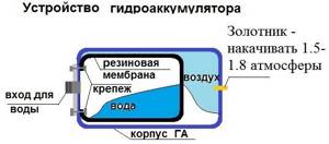
Diagram of the hydraulic accumulator
When the tank is filled with liquid, the membrane stretches and compresses the air until the pressure is equal to the action of the compressed air. Then a special valve opens, air is squeezed out of the container into the water. When the pressure in the pipes drops to the parameter when the pressure switch is triggered, the pump starts working, adding liquid to the device’s tank.
The pump continues to operate for some time after the tap is closed, this occurs until the force equalizes to a certain level, leading to the activation of the second sensor. To protect pumping equipment from premature wear, filters are placed at the system inlet. In some models, membranes for hydraulic accumulators are replaced with a flexible bulb.
The main purpose of such tanks is to maintain water pressure in the water supply. This is a necessary condition for the pump; there must always be normal liquid pressure in the tap, otherwise it turns on and off several times within a second. Therefore, breakdown is inevitable. Hydraulic accumulators are designed to prevent such undesirable situations. Thus, the following tasks of expansion membrane tanks can be distinguished:
- automation of the water supply process;
- maintaining and ensuring a smooth change in water pressure in the system;
- protection against water hammer;
- limiting repeated short-term starts of the pump, increasing its service life;
- providing a minimum supply of fluid.
Types of expansion machines
The following types of reservoirs under hydraulic power are distinguished:
- Expansion machines with mechanical storage. They are divided into: spring and load. Due to a number of shortcomings, they have limited use in practice and are not widely used.
- Expansion machines with pneumatic storage. They have demonstrated high energy intensity with minimal dimensions, low inertia, and are characterized by simplicity of design and reliability. Depending on the separating elements, there are piston, membrane and balloon devices. The latter are the most common type for medium flow in fast-acting hydraulic systems. The separating base is a rubber cylinder under gas pressure. The fluid cavity is connected to the system. When the pressure in the water supply increases, the cylinder compresses and absorbs a certain amount of water into the accumulator; when it decreases, the compressed gas displaces the liquid back into the system. The piston works on the same principle, the difference is in the separation medium for which the piston is used. Their low cost is due to the simplicity of the design, while providing a large volume (up to 500 liters). Membrane ones have the advantage of small dimensions. Installed where rapid release of energy is required. However, the capacity of the working fluid is small. The separator is a rubber membrane.
- Hydrophores for hot water supply, painted blue, are also on sale.
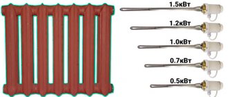
- A vertical reservoir has been created for submersible pumps. A 24-liter hydraulic accumulator is preferable for pumping units with a power of up to 600 W, vessels with a capacity of 50 liters - for pumps whose power reaches 1 kW, a 100-liter hydraulic accumulator - for pumping equipment up to 1.5 kW. There are also horizontal layouts recommended for operation with surface pumps.
List of sources
- sovet-ingenera.com
- py-sm.com
- stroy-podskazka.ru
- remontir.info
- iseptick.ru
- StrojDvor.ru
- nasosovnet.ru
- inhouze.info
- homeli.ru
- Author: Sergey
Share with your friends!